Thermodynamic Analysis of a Condensate Heating System from a Marine Steam Propulsion Plant with Steam Reheating
https://doi.org/10.1007/s11804-021-00191-5
-
Abstract
The thermodynamic (energy and exergy) analysis of a condensate heating system, its segments, and components from a marine steam propulsion plant with steam reheating is performed in this paper. It is found that energy analysis of any condensate heating system should be avoided because it is highly influenced by the measuring equipment accuracy and precision. All the components from the observed marine condensate heating system have energy destructions lower than 3 kW, while the energy efficiencies of this system are higher than 99%. The exergy efficiency of closed condensate heaters continuously increases from the lowest to the highest steam pressures (from 70.10% to 92.29%). The ambient temperature variation between 5 ℃ and 45 ℃ notably influences the exergy efficiency change of both low pressure heaters and the low pressure segment equal to 31.61%, 12.37%, and 18.35%, respectively.Highlights• Energy and exergy analyses of a condensate heating system from a marine steam propulsion plant are performed.• In a properly balanced system, exergy efficiency of closed condensate heaters continuously increases from the lowest to the highest pressures.• The closed condensate heater that operates with the lowest steam pressure is most influenced by the ambient temperature change.• Energy analysis of this system should be avoided because it is highly influenced by the measuring equipment accuracy and precision. -
1 Introduction
Modern steam power plants consist of various systems that improve the entire plant operation (Li et al. 2017; Chen et al. 2017a). One such system is a condensate heating system mounted between the main condenser and steam generator (Abdella and Nassar 2019) in which the condensate is heated by steam extracted from the main turbine cylinders (Rocha and Silva 2019; Hoseinzadeh and Heyns 2020). The main goal of the condensate heating system is to reduce fuel consumption and simultaneously increase overall plant efficiency (Woodruff et al. 2004; Oyedepo et al. 2020).
Many researchers have investigated condensate heating systems and their components as part of a steam power plant analysis. Naserabad et al. (2019) presented multi-objective optimization of condensate heater arrangement options in a steam power plant repowering. Economic and thermal performance analysis of a 210-MW coal-fired steam power plant was presented by Kumar et al. (2014), where the components of the existing condensate heating system were investigated in detail. These authors have also presented several improvement options. Chauhan and Khanam (2019) used pinch analysis to integrate improvements from the energy aspect in a 250-MW thermal power plant. It was concluded that the best integration option was to close one extraction, which leads steam to the condensate heater nearest the main condenser. Zhao et al. (2018) performed dynamic simulation that shows that the operational flexibility of a 660-MW coal-fired steam power plant can be improved by regulating steam extractions to high pressure condensate heaters. The fatigue lifetime assessment of a high pressure heater in supercritical coal-fired power plants was investigated by Zhao et al. (2019). These authors concluded that such a heater obtains maximum mechanical stresses before it reaches thermal stresses. Many researchers performed failure analysis of various condensate heaters from thermal or nuclear power plants (Zangeneh and Bakhtiari 2019; Ramesh and Manavalan 2019; Fulger et al. 2019). Several operation schemes of condensate heaters were investigated by Wijaya and Widodo (2019) using Cycle-Tempo software, while Geete (2020) investigated the possibilities of using a parabolic solar collector in condensate heating systems.
During energy and exergy analyses of steam power plants, condensate heating system components are commonly considered. Energy and exergy analyses of a 200-MW steam power plant along with an investigation of the optimal number of condensate heaters were presented by Kamil Mohammed et al. (2019). Kumar et al. (2018) performed energy and exergy analyses of a coal-fired power plant along with an investigation of a currently operating condensate heating system. Similar research for various power plants can be found in the papers by Khan et al. (2019), Kowalczyk et al. (2019), and Adeli et al. (2020). Kaushik et al. (2011) and Ray et al. (2010) presented reviews, equations, methods, and techniques for energy and exergy analyses of various thermal power plants that include condensate heating systems and their components. The results show that proper condensate heating system operation significantly influences the performance of the entire power plant.
The energy and exergy analyses of a condensate heating system, its segments, and components from a marine steam propulsion plant with steam reheating are performed in this paper. It is found that the energy analysis of this system is highly influenced by the measurement equipment accuracy and precision, and it can provide unrealistic results, so the exergy analysis is favored. A detailed literature review shows that an ambient temperature change analysis for each component of any condensate heating system has not been performed to date. This analysis shows that the condensate heater nearest the steam condenser is highly influenced by an ambient temperature change. Moreover, the ambient temperature change has an important influence on the entire low pressure heating segment, which is useful for proper design and maintenance.
2 Marine Steam Propulsion Plant with Steam Reheating
Current marine propulsion plants are mainly based on internal combustion engines (Prasad Sinha and Balaji 2018; Cherednichenko and Serbin 2018; Senčić et al. 2019; Lamas Galdo et al. 2020). However, steam propulsion plants remain dominant for LNG carrier drives because of their high reliability, operational flexibility, and specificity of transported cargo (Adamkiewicz and Grzesiak 2019). Older versions of marine steam propulsion plants have a main turbine composed of two cylinders (high pressure turbine (HPT) cylinder and low pressure turbine (LPT) cylinder) and do not perform steam reheating (Mrzljak et al. 2017a; Mrzljak and Poljak 2019). Newer versions of these steam propulsion plants, as presented in Figure 1, perform steam reheating and had an additional cylinder (intermediate pressure turbine (IPT) cylinder).
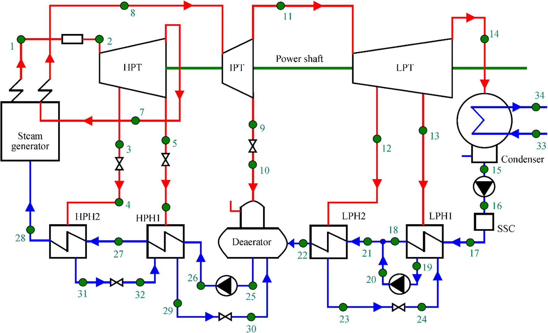 Figure 1 Scheme of the marine steam propulsion plant with steam reheating
Presently, marine steam propulsion plants (with and without reheating) can be found on various LNG carriers. The total produced power in such plants is between 35 MW and 45 MW (Fernández et al. 2017) and includes the main turbine, all turbo-generators, and the low power steam turbine for the main condensate pump drive (Kocijel et al. 2020). However, steam propulsion plants can also be effectively used in other marine vessels, such as crude oil carriers.
Steam reheating application increases the overall plant efficiency and divides the main turbine at three cylinders. All main turbine cylinders are connected to the shaft, which drives the main propulsion propeller through the gearbox (Song et al. 2015). The steam propulsion plant presented in Figure 1 is used for the crude oil carrier drive, and the main turbine maximum power is 17 MW (Koroglu and Sogut 2018).
3 Description and Characteristics of the Analyzed Marine Condensate Heating System
The analyzed condensate heating system (Figure 2) consists of five basic components, four of which are closed condensate low pressure and high pressure heaters (LPH1, LPH2, HPH1, and HPH2). Closed condensate heaters are recuperative heat exchangers in which heat transfer occurs through pipe walls, so the heating medium and main condensate are not mixed together.
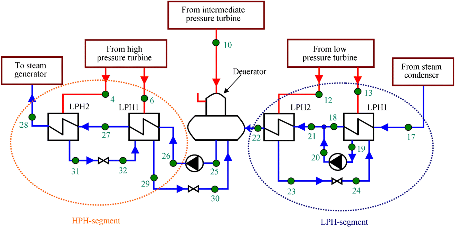 Figure 2 Analyzed marine condensate heating system, its segments, and components
The fifth basic component of the analyzed system is the deaerator, which has a dual function. The deaerator is an open condensate heater in which the heating medium (steam) and the main condensate are mixed. The second deaerator function is dissolved gas removal (deaerating process) to prevent erosion (Chen et al. 2017b).
Along with the five basic components, the analyzed marine condensate heating system consists of several pressure reduction valves and pumps.
4 Equations for the Energy and Exergy Analyses
4.1 Governing Equations for the Energy and Exergy Analyses of Any Control Volume
Energy analysis of any control volume is defined by the first law of thermodynamics (Aljundi 2009; Elhelw et al. 2019; Ahmadi et al. 2018; Kanoğlu et al. 2012). For any control volume, the energy balance equation can be defined as Adibhatla and Kaushik (2017a), where in the most cases, potential and kinetic energies can be disregarded (Medica-Viola et al. 2020a):
$$ {\overset{\cdot }{Q}}_{\mathrm{IN}}+{P}_{\mathrm{IN}}+\sum \overset{\cdot }{E}\kern-0.2em {n}_{\mathrm{IN}}={\overset{\cdot }{Q}}_{\mathrm{OUT}}+{P}_{\mathrm{OUT}}+\sum \overset{\cdot }{E}\kern-0.2em {n}_{\mathrm{OUT}} $$ (1) In Eq. 1, $ \overset{\cdot }{Q} $ is heat energy transfer, P is mechanical power, while indexes IN and OUT denotes input and output. $ \overset{\cdot }{E}\;n $ is the total energy of a fluid flow defined according to (Blažević et al. 2019):
$$ \overset{\cdot }{E}\kern-0.2em n=\overset{\cdot }{m}\cdot h $$ (2) where $ \overset{\cdot }{m} $ is mass flow rate and h is specific enthalpy.
Exergy analysis of any control volume is defined by the second law of thermodynamics (Naserbegi et al. 2018; Adibhatla and Kaushik 2017b). The exergy balance equation is (Medica-Viola et al. 2020b):
$$ {\overset{\cdot }{X}}_{\mathrm{heat},\mathrm{IN}}+{P}_{\mathrm{IN}}+\sum \overset{\cdot }{E}\kern-0.2em {x}_{\mathrm{IN}}={\overset{\cdot }{X}}_{\mathrm{heat},\mathrm{OUT}}+{P}_{\mathrm{OUT}}+\sum \overset{\cdot }{E}\kern-0.2em {x}_{\mathrm{OUT}}\\ \;\;\;\;\;\;\;\;\;\;\;\;\;\;\;\;\;\;\;\;\;\;\;\;\;\;\;\;\;\;\;\;\;\;\;\;\;\;\;+\overset{\cdot }{E}\kern-0.2em {x}_{\mathrm{D}} $$ (3) $ \overset{\cdot }{E}\kern-0.2em x $ is the total exergy of a fluid flow, defined according to Mrzljak et al. (2019) as
$$ \overset{\cdot }{E}\kern-0.2em x=\overset{\cdot }{m}\cdot \varepsilon $$ (4) where ε is the specific exergy of the fluid stream (Tan et al. 2018):
$$ \varepsilon =\left(h-{h}_0\right)-{T}_0\cdot \left(s-{s}_0\right) $$ (5) In Eq. 5, s is specific entropy, while $ {\overset{\cdot }{X}}_{\mathrm{heat}} $ represents the heat exergy transfer at temperature T:
$$ {\overset{\cdot }{X}}_{\mathrm{heat}}=\sum \left(1-\frac{T_0}{T}\right)\cdot \overset{\cdot }{Q} $$ (6) Energy and exergy efficiencies of any control volume can be defined as
$$ {\eta}_{\mathrm{I}\left(\mathrm{II}\right)}=\frac{\mathrm{cumulative}\kern0.5em \mathrm{energy}\kern0.5em \left(\mathrm{or}\kern0.5em \mathrm{exergy}\right)\kern0.5em \mathrm{power}\kern0.5em \mathrm{output}}{\mathrm{cumulative}\kern0.5em \mathrm{energy}\kern0.5em \left(\mathrm{or}\kern0.5em \mathrm{exergy}\right)\kern0.5em \mathrm{power}\kern0.5em \mathrm{input}} $$ (7) During control volume operation, fluid mass flow rate leakage usually does not occur, so the valid mass flow rate balance is (Lorencin et al. 2019a)
$$ \sum {\overset{\cdot }{m}}_{\mathrm{IN}}=\sum {\overset{\cdot }{m}}_{\mathrm{OUT}} $$ (8) 4.2 Equations for the Energy and Exergy Analyses of the Investigated Heaters
Energy and exergy analyses of all condensate heaters are performed using equations from Erdem et al. (2009), Uysal et al. (2017), and Noroozian et al. (2017). All the equations are developed according to the operating points from Figures 1 and 2 (green marked points). The energy analysis equations are presented in Table 1.
Table 1 Energy analysis equations of condensate heatersComp. Energy power input Energy power output Energy destruction (energy power loss) Energy efficiency LPH1 $ {\displaystyle \begin{array}{l}\overset{\cdot }{E}{n}_{\mathrm{IN},\mathrm{LPH}1}=\\ {}=\overset{\cdot }{E}{n}_{13}+\overset{\cdot }{E}{n}_{24}-\overset{\cdot }{E}{n}_{19}\end{array}} $ ${\displaystyle \begin{array}{l}\overset{\cdot }{E}{n}_{\mathrm{OUT},\mathrm{LPH}1}=\\ {}=\overset{\cdot }{E}{n}_{18}-\overset{\cdot }{E}{n}_{17}\end{array}} $ ${\displaystyle \begin{array}{l}\overset{\cdot }{E}{n}_{\mathrm{D},\mathrm{LPH}1}=\\ {}=\overset{\cdot }{E}{n}_{\mathrm{IN},\mathrm{LPH}1}-\overset{\cdot }{E}{n}_{\mathrm{OUT},\mathrm{LPH}1}\end{array}} $ ${\eta}_{\mathrm{I},\mathrm{LPH}1}=\frac{\overset{\cdot }{E}{n}_{\mathrm{OUT},\mathrm{LPH}1}}{\overset{\cdot }{E}{n}_{\mathrm{I}\mathrm{N},\mathrm{LPH}1}} $ LPH2 ${\displaystyle \begin{array}{l}\overset{\cdot }{E}{n}_{\mathrm{IN},\mathrm{LPH}2}=\\ {}=\overset{\cdot }{E}{n}_{12}-\overset{\cdot }{E}{n}_{23}\end{array}} $ ${\displaystyle \begin{array}{l}\overset{\cdot }{E}{n}_{\mathrm{OUT},\mathrm{LPH}2}=\\ {}=\overset{\cdot }{E}{n}_{22}-\overset{\cdot }{E}{n}_{21}\end{array}} $ ${\displaystyle \begin{array}{l}\overset{\cdot }{E}{n}_{\mathrm{D},\mathrm{LPH}2}=\\ {}=\overset{\cdot }{E}{n}_{\mathrm{IN},\mathrm{LPH}2}-\overset{\cdot }{E}{n}_{\mathrm{OUT},\mathrm{LPH}2}\end{array}} $ ${\eta}_{\mathrm{I},\mathrm{LPH}2}=\frac{\overset{\cdot }{E}{n}_{\mathrm{OUT},\mathrm{LPH}2}}{\overset{\cdot }{E}{n}_{\mathrm{I}\mathrm{N},\mathrm{LPH}2}} $ DEA $ {\displaystyle \begin{array}{l}\overset{\cdot }{E}{n}_{\mathrm{IN},\mathrm{DEA}}=\\ {}=\overset{\cdot }{E}{n}_{10}+\overset{\cdot }{E}{n}_{22}+\overset{\cdot }{E}{n}_{30}\end{array}}$ $\(\overset{\cdot }{E}{n}_{\mathrm{OUT}, \mathrm{DEA}}=\overset{\cdot }{E}{n}_{25} \) ${\displaystyle \begin{array}{l}\overset{\cdot }{E}{n}_{\mathrm{D},\mathrm{DEA}}=\\ {}=\overset{\cdot }{E}{n}_{\mathrm{IN},\mathrm{DEA}}-\overset{\cdot }{E}{n}_{\mathrm{OUT},\mathrm{DEA}}\end{array}} $ ${\eta}_{\mathrm{I},\mathrm{DEA}}=\frac{\overset{\cdot }{E}{n}_{\mathrm{OUT},\mathrm{DEA}}}{\overset{\cdot }{E}{n}_{\mathrm{I}\mathrm{N},\mathrm{DEA}}} $ HPH1 ${\displaystyle \begin{array}{l}\overset{\cdot }{E}{n}_{\mathrm{IN},\mathrm{HPH}1}=\\ {}=\overset{\cdot }{E}{n}_6+\overset{\cdot }{E}{n}_{32}-\overset{\cdot }{E}{n}_{29}\end{array}} $ ${\displaystyle \begin{array}{l}\overset{\cdot }{E}{n}_{\mathrm{OUT},\mathrm{HPH}1}=\\ {}=\overset{\cdot }{E}{n}_{27}-\overset{\cdot }{E}{n}_{26}\end{array}} $ ${\displaystyle \begin{array}{l}\overset{\cdot }{E}{n}_{\mathrm{D},\mathrm{HPH}1}=\\ {}=\overset{\cdot }{E}{n}_{\mathrm{IN},\mathrm{HPH}1}-\overset{\cdot }{E}{n}_{\mathrm{OUT},\mathrm{HPH}1}\end{array}} $ ${\eta}_{\mathrm{I},\mathrm{HPH}1}=\frac{\overset{\cdot }{E}{n}_{\mathrm{OUT},\mathrm{HPH}1}}{\overset{\cdot }{E}{n}_{\mathrm{I}\mathrm{N},\mathrm{HPH}1}} $ HPH2 ${\displaystyle \begin{array}{l}\overset{\cdot }{E}{n}_{\mathrm{IN},\mathrm{HPH}2}=\\ {}=\overset{\cdot }{E}{n}_4-\overset{\cdot }{E}{n}_{31}\end{array}} $ ${\displaystyle \begin{array}{l}\overset{\cdot }{E}{n}_{\mathrm{OUT},\mathrm{HPH}2}=\\ {}=\overset{\cdot }{E}{n}_{28}-\overset{\cdot }{E}{n}_{27}\end{array}} $ ${\displaystyle \begin{array}{l}\overset{\cdot }{E}{n}_{\mathrm{D},\mathrm{HPH}2}=\\ {}=\overset{\cdot }{E}{n}_{\mathrm{IN},\mathrm{HPH}2}-\overset{\cdot }{E}{n}_{\mathrm{OUT},\mathrm{HPH}2}\end{array}} $ ${\eta}_{\mathrm{I},\mathrm{HPH}2}=\frac{\overset{\cdot }{E}{n}_{\mathrm{OUT},\mathrm{HPH}2}}{\overset{\cdot }{E}{n}_{\mathrm{I}\mathrm{N},\mathrm{HPH}2}} $ Exergy analysis of each condensate heater is performed using the same equations from Table 1 while replacing the total energy of a flow ($ \overset{\cdot }{E}\kern-0.2em n $) with the total exergy of a flow ($ \overset{\cdot }{E}\kern-0.2em x $) and the energy efficiency (ηI) with the exergy efficiency (ηII). These replacements are made in all the equations for each heater.
4.3 Equations for the Energy and Exergy Analyses of Segments and the Overall Heating System
In many research papers can be found the energy and exergy analyses of each heater from a condensate heating system (Zhao et al. 2017). This paper offers a certain upgrade.
The observed marine condensate heating system is divided into two segments. The first segment is a low pressure heating segment, which encompasses both low pressure condensate heaters (LPH1 and LPH2). The second segment (high pressure heating segment) contains both high pressure condensate heaters (HPH1 and HPH2) (Figure 2). The deaerator is a component that divides the condensate heating system in two presented segments; it is analyzed separately as a component and within the entire system. The energy analysis equations of the overall condensate heating system and its segments are presented in Table 2.
Table 2 Energy analysis equations of the condensate heating system and its segmentsComp. Energy power input Energy power output Energy destruction (energy power loss) Energy efficiency LPHS ${\displaystyle \begin{array}{l}\overset{\cdot }{E}{n}_{\mathrm{IN},\mathrm{LPHS}}=\\ {}=\overset{\cdot }{E}{n}_{12}+\overset{\cdot }{E}{n}_{13}-\overset{\cdot }{E}{n}_{19}\end{array}} $ ${\displaystyle \begin{array}{l}\overset{\cdot }{E}{n}_{\mathrm{OUT},\mathrm{LPHS}}=\\ {}=\overset{\cdot }{E}{n}_{22}-\overset{\cdot }{E}{n}_{17}-\overset{\cdot }{E}{n}_{20}\end{array}} $ ${\displaystyle \begin{array}{l}\overset{\cdot }{E}{n}_{\mathrm{D},\mathrm{LPHS}}=\\ {}=\overset{\cdot }{E}{n}_{\mathrm{IN},\mathrm{LPHS}}-\overset{\cdot }{E}{n}_{\mathrm{OUT},\mathrm{LPHS}}\end{array}} $ ${\eta}_{\mathrm{I},\mathrm{LPHS}}=\frac{\overset{\cdot }{E}{n}_{\mathrm{OUT},\mathrm{LPHS}}}{\overset{\cdot }{E}{n}_{\mathrm{I}\mathrm{N},\mathrm{LPHS}}} $ HPHS ${\displaystyle \begin{array}{l}\overset{\cdot }{E}{n}_{\mathrm{IN},\mathrm{HPHS}}=\\ {}=\overset{\cdot }{E}{n}_4+\overset{\cdot }{E}{n}_6-\overset{\cdot }{E}{n}_{29}\end{array}} $ $\overset{\cdot }{E}{n}_{\mathrm{OUT},\mathrm{HPHS}}=\overset{\cdot }{E}{n}_{28}-\overset{\cdot }{E}{n}_{26} $ ${\displaystyle \begin{array}{l}\overset{\cdot }{E}{n}_{\mathrm{D},\mathrm{HPHS}}=\\ {}=\overset{\cdot }{E}{n}_{\mathrm{IN},\mathrm{HPHS}}-\overset{\cdot }{E}{n}_{\mathrm{OUT},\mathrm{HPHS}}\end{array}} $ ${\eta}_{\mathrm{I},\mathrm{HPHS}}=\frac{\overset{\cdot }{E}{n}_{\mathrm{OUT},\mathrm{HPHS}}}{\overset{\cdot }{E}{n}_{\mathrm{I}\mathrm{N},\mathrm{HPHS}}} $ CHS ${\displaystyle \begin{array}{l}\overset{\cdot }{E}{n}_{\mathrm{IN},\mathrm{CHS}}=\overset{\cdot }{E}{n}_{\mathrm{IN},\mathrm{LPHS}}+\\ {}+\overset{\cdot }{E}{n}_{\mathrm{IN},\mathrm{HPHS}}+\overset{\cdot }{E}{n}_{\mathrm{IN},\mathrm{DEA}}\end{array}} $ ${\displaystyle \begin{array}{l}\overset{\cdot }{E}{n}_{\mathrm{OUT},\mathrm{CHS}}=\overset{\cdot }{E}{n}_{\mathrm{OUT},\mathrm{LPHS}}+\\ {}+\overset{\cdot }{E}{n}_{\mathrm{OUT},\mathrm{HPHS}}+\overset{\cdot }{E}{n}_{\mathrm{OUT},\mathrm{DEA}}\end{array}} $ ${\displaystyle \begin{array}{l}\overset{\cdot }{E}{n}_{\mathrm{D},\mathrm{CHS}}=\\ {}=\overset{\cdot }{E}{n}_{\mathrm{IN},\mathrm{CHS}}-\overset{\cdot }{E}{n}_{\mathrm{OUT},\mathrm{CHS}}\end{array}} $ ${\eta}_{\mathrm{I},\mathrm{CHS}}=\frac{\overset{\cdot }{E}{n}_{\mathrm{OUT},\mathrm{CHS}}}{\overset{\cdot }{E}{n}_{\mathrm{I}\mathrm{N},\mathrm{CHS}}} $ Exergy analysis of the overall heating system and its segments is performed using the same equations from Table 2 while replacing the total energy of a flow ($ \overset{\cdot }{E}\kern-0.2em n $) with the total exergy of a flow ($ \overset{\cdot }{E}\kern-0.2em x $) and the energy efficiency (ηI) with the exergy efficiency (ηII). For energy and exergy analyses of the overall condensate heating system and its segments, the operating points are defined according to Figures 1 and 2. The base ambient state is selected as proposed in Koroglu and Sogut (2018)—the ambient pressure of 1 bar and the ambient temperature of 15 ℃.
5 Data Required for the Energy and Exergy Analyses
All fluid stream data required for the energy and exergy analyses of the marine condensate heating system, its segments, and components were found in Koroglu and Sogut (2018) and are presented in Table 3. The specific enthalpy and specific entropy of each fluid stream are calculated using NIST REFPROP 9.0 software (Lemmon et al. 2010). The specific exergy of each fluid stream at the selected base ambient state is calculated using Eq. 5.
Table 3 Thermodynamic data of required fluid streamsOperating point* Stream mass flow rate (kg/s) Stream pressure (kPa) Stream temperature (℃) Stream specific enthalpy (kJ/kg) Stream specific entropy (kJ/kg·K) Stream specific exergy at the base ambient state (kJ/kg) 4 1.055 3 770 397.26 3 211.70 6.793 1 256.02 6 1.679 2 120 325.46 3 079.20 6.837 1 111.01 10 0.421 520 341.56 3 149.80 7.587 965.37 12 0.808 240 249.92 2 969.40 7.623 774.63 13 0.683 60 126.97 2 734.10 7.746 503.93 17 10.947 520 42.80 179.06 0.607 5.69 18 10.947 520 81.23 339.75 1.088 28.09 19 1.491 60 85.93 359.10 1.144 31.43 20 1.491 520 85.98 359.86 1.144 31.93 21 12.438 520 81.80 342.31 1.095 28.54 22 12.438 520 119.37 500.65 1.519 64.75 23 0.808 240 126.07 528.99 1.591 72.23 24 0.808 60 85.93 528.99 1.616 64.97 25 15.593 520 153.32 645.87 1.874 107.74 26 15.593 10 300 155.03 659.20 1.880 119.28 27 15.593 10 300 210.35 901.55 2.412 208.33 28 15.593 10 300 241.87 1 046.45 2.703 269.56 29 2.734 2 120 215.35 921.45 2.473 210.75 30 2.734 520 153.32 921.45 2.520 197.13 31 1.055 3 770 246.87 1 069.90 2.764 275.44 32 1.055 2 120 215.35 1 069.90 2.777 271.57 *Operating point numeration refers to Figure 2 6 Energy and Exergy Analysis Results
6.1 Energy and Exergy Analyses in the Base Ambient State
The results of the energy analysis of the marine condensate heating system, its segments, and components are presented in Figure 3. The energy destruction of LPHS is higher than that of HPHS and mostly caused by energy destruction of LPH2 (Figure 3). LPH2 and the deaerator have the highest energy destructions, while all other condensate heating system components have energy destructions lower than 1 kW. Comparison of all five components (heaters) shows that the lowest energy efficiency has LPH2 (99.877%). Because of the LPH2 influence, LPHS has a lower energy efficiency (99.927%) than that of HPHS (99.988%). The overall condensate heating system has an energy destruction equal to 4.77 kW and an energy efficiency equal to 99.976%, as presented in Figure 3.
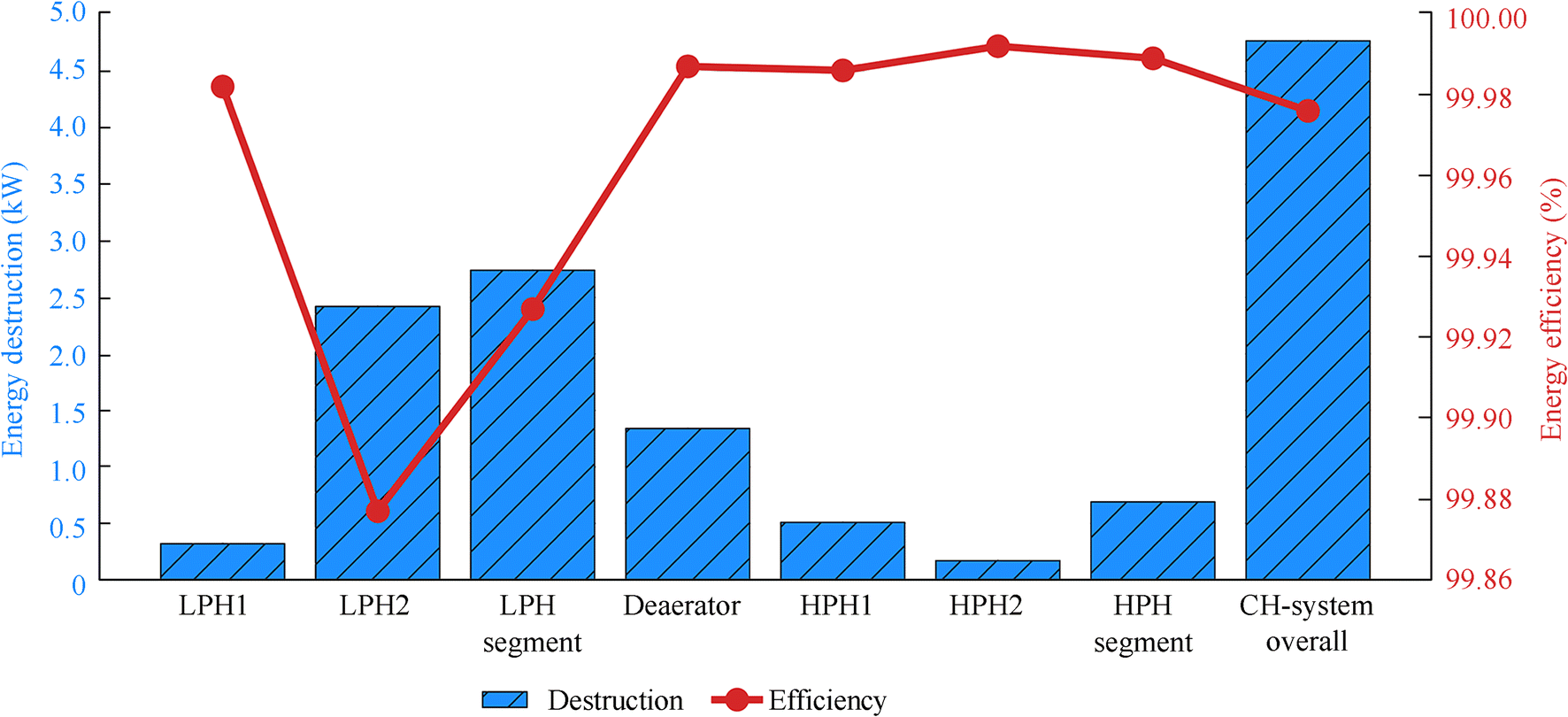 Figure 3 Energy efficiencies and destructions (losses) of the condensate heating system, its segments, and components
The results of the energy analysis lead to the conclusion that this analysis should be avoided for any condensate heating system, its segments, or components. Low energy destructions (and simultaneously high energy efficiencies) do not allow even the smallest errors during data acquisition. While observing HPH2, a decrease in steam specific enthalpy (operating point 4, Table 3) of 0.2 kJ/kg led to a negative energy destruction and to an energy efficiency higher than 100%, which is practically impossible.
By observing all the components (heaters) from the analyzed marine condensate heating system at the base ambient state, it can be easily noted that the deaerator has the dominant exergy power inputs and outputs (Figure 4). HPHS has approximately threefold higher exergy power inputs and outputs than those of LPHS. The overall condensate heating system has an exergy power input equal to 5 278.31 kW, while its exergy power output equals 4 718.9 kW.
 Figure 4 Exergy power inputs and outputs of the condensate heating system, its segments, and components (base ambient state)
In the base ambient state of the observed condensate heating system, the deaerator is the component with the lowest exergy destruction (70.74 kW) and the highest exergy efficiency (95.96%) (Figure 5). High pressure condensate heaters have much higher exergy efficiencies than those of low pressure heaters. HPH1 has a lower exergy efficiency (88.12%) than that of HPH2 (92.29%) because of a higher exergy destruction. In the low pressure heating segment, LPH2 has a higher exergy efficiency (79.36%) than that of LPH1 (70.10%), despite the higher exergy destruction.
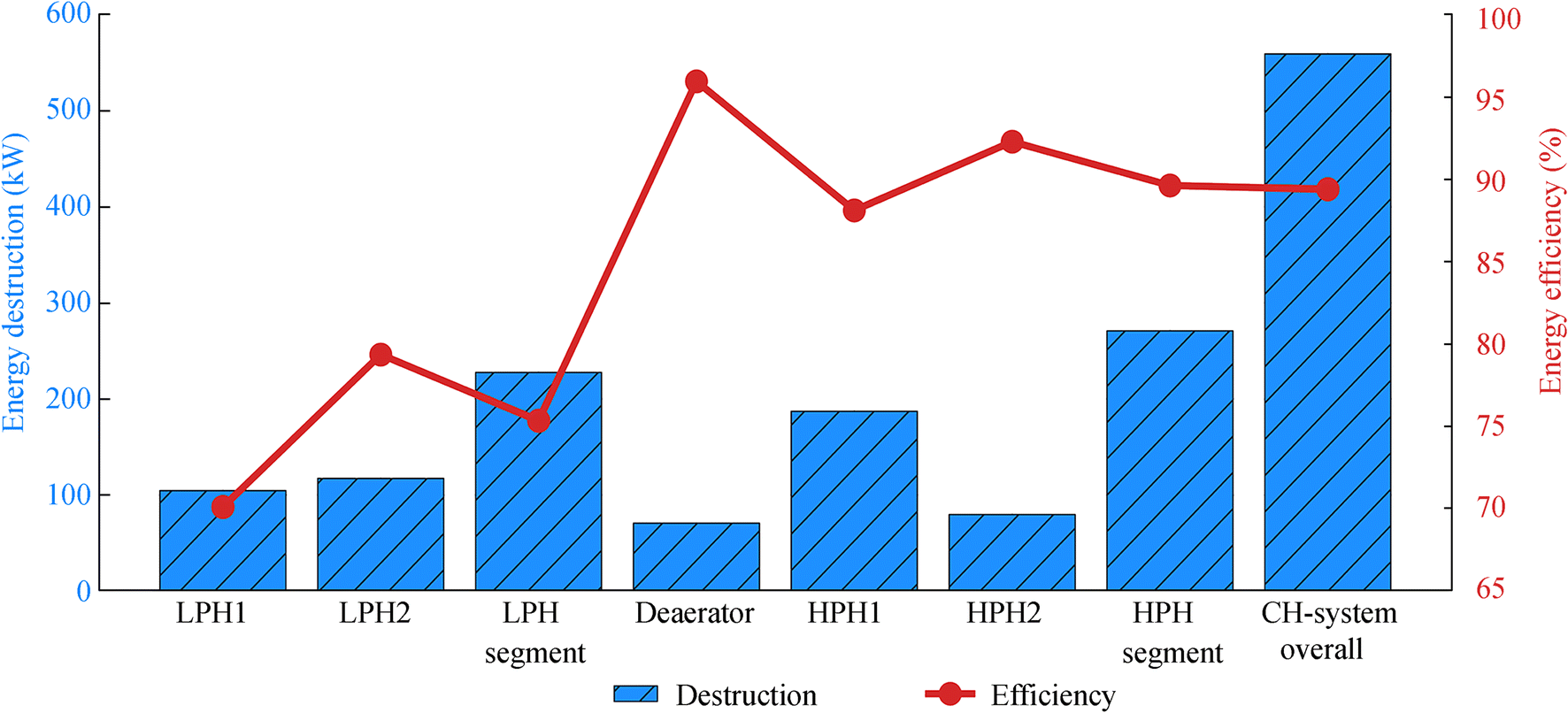 Figure 5 Exergy efficiencies and destructions of the condensate heating system and its segments and components (base ambient state)
Despite its lower exergy destruction, LPHS has a lower exergy efficiency (75.34%) than that of HPHS (89.63%) (Figure 5). Overall, the analyzed condensate heating system has an exergy destruction of 559.41 kW, while its exergy efficiency is 89.40%. Compared with the energy analysis, the exergy analysis of the observed (and any other) condensate heating system is less sensitive to the measuring equipment accuracy and precision (Naserbegi et al. 2018), and it can be recommended.
6.2 Exergy Analysis During the Ambient Temperature Change
A literature review shows that several researchers have investigated the ambient temperature influence on steam power plant components. The general conclusion is that most steam power plant components are not significantly influenced by the ambient temperature change. As an example, Ameri et al. (2009) showed that an ambient temperature change of 10 ℃ resulted in a 1% or smaller exergy efficiency change of high power steam turbines. The same conclusion is reached in Mrzljak et al. (2017b) for marine auxiliary low power steam turbines. However, Ahmadi and Toghraie (2016) showed that most steam power plant components are not significantly influenced by the ambient temperature change but found exceptions in steam generators and low pressure steam turbine cylinders. Kopac and Hilalci (2007) and Aljundi (2009) found that condensate heaters from land-based steam power plants are slightly influenced by an ambient temperature change. As opposed to land-based steam power plants, Poljak et al. (2020) showed that an ambient temperature change can notably influence heat exchangers from a marine steam power plant.
In this paper, the ambient temperature influence on the analyzed marine condensate heating system, its segments, and components is also investigated. The observed ambient temperature range is set from 5 to 45 ℃, and the calculations are performed in steps of 10 ℃. An analysis of condensate heating system components (heaters) shows that the exergy destruction of each heater increases with the ambient temperature, as presented in Figure 6.
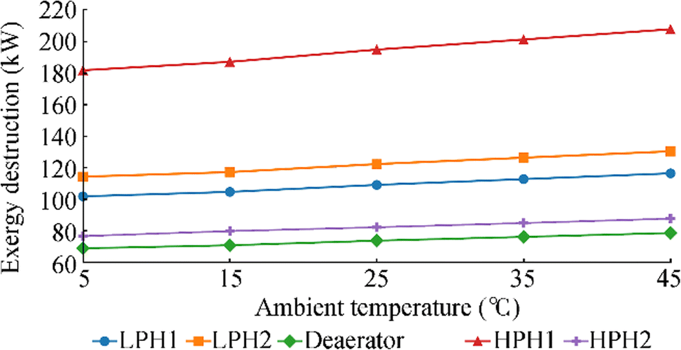 Figure 6 Exergy destruction of condensate heating system components during an ambient temperature change
An increase in the ambient temperature decreases the exergy efficiencies of all heaters (Figure 7). The ambient temperature change slightly influenced the exergy efficiencies of HPH2, the deaerator, and HPH1 and highly influenced those of both low pressure heaters (LPH2 and LPH1) (Figure 7). In the observed ambient temperature range, the cumulative exergy efficiency change of HPH2, the deaerator, and HPH1 equals 2.55%, 3.83%, and 4.43%, respectively, while that of LPH2 and LPH1 is 12.37% and 31.61%, respectively.
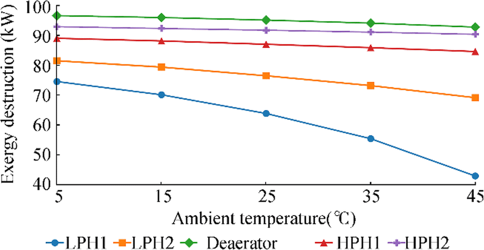 Figure 7 Exergy efficiency of condensate heating system components during an ambient temperature change
The important conclusion derived from this observation is that the influence of the ambient temperature differs between condensate heaters. The exergy efficiency of a condensate heater mounted nearest the main condenser is highly influenced by the ambient temperature change. Because of this fact, attention should be paid to the design and operation of this condensate heater.
The exergy destructions of LPHS and HPHS, as well as the overall condensate heating system, increase with the ambient temperature (Figure 8). The change in the ambient temperature resulted in a more intensive exergy destruction change of HPHS (in comparison with that of LPHS). In the observed ambient temperature range, the exergy destruction of the entire condensate heating system increases from 543.21 kW (at 5 ℃) to 620.73 kW (at 45 ℃) (Figure 8).
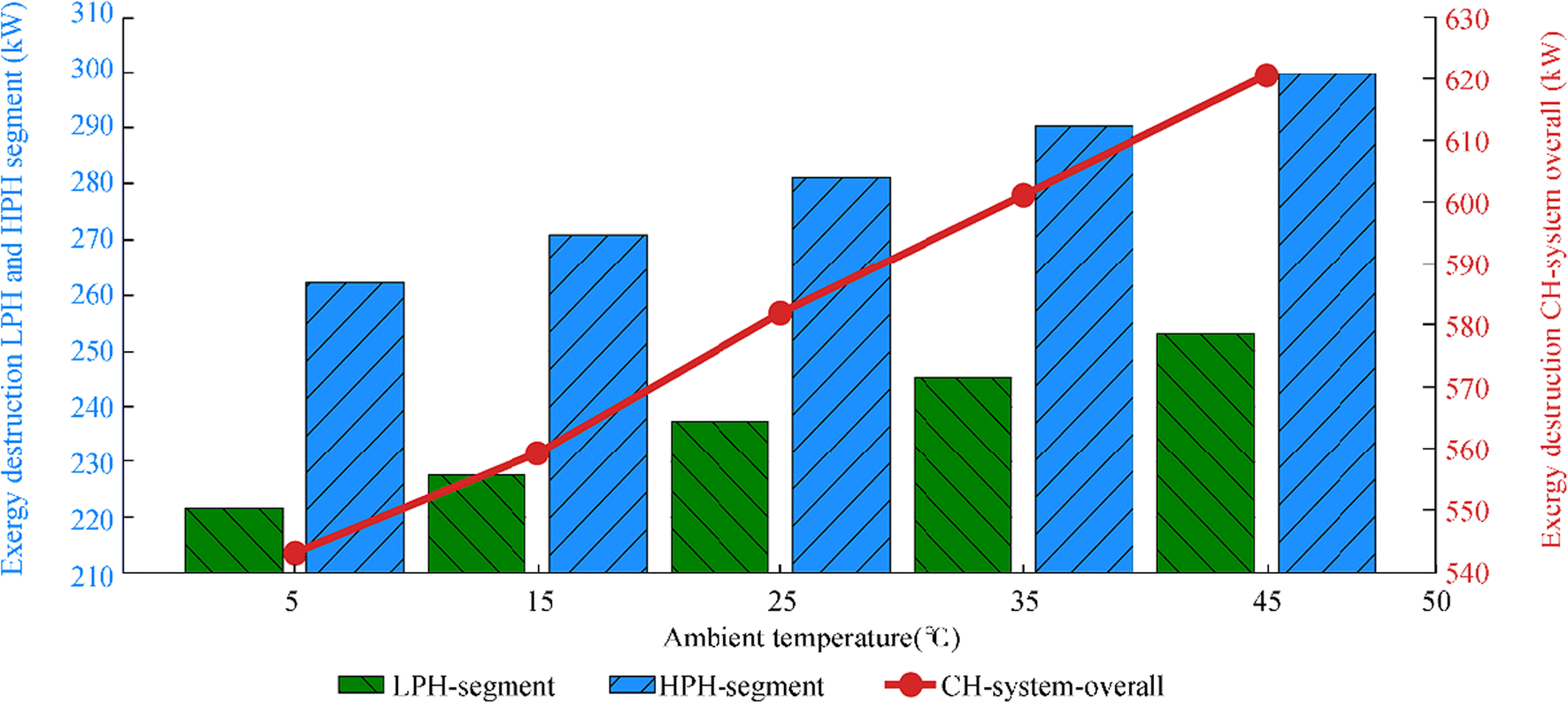 Figure 8 Exergy destruction of the condensate heating system and its segments during an ambient temperature change
For the overall condensate heating system and both of its segments (as for the heaters), it is also valid that an increase in the ambient temperature decreases exergy efficiencies. Figure 9 shows that the exergy efficiencies of HPHS and the overall condensate heating system are not significantly influenced by the ambient temperature change. However, the ambient temperature change has a notable influence on the LPHS exergy efficiency. In the observed ambient temperature range, the cumulative change in the exergy efficiency of HPHS, the overall condensate heating system, and LPHS is 3.69%, 6.23%, and 18.35%, respectively. This fact leads to the conclusion that the entire LPHS (not only the condensate heater nearest the main condenser) should be carefully designed and maintained.
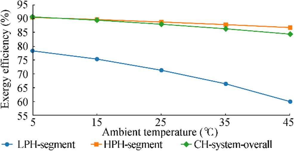 Figure 9 Exergy efficiency of the condensate heating system and its segments during the ambient temperature change
Figure 10 shows the average percentage difference of exergy power output and input for the overall analyzed condensate heating system, its segments, and components in the observed ambient temperature range (from 5 to 45 ℃). An average percentage difference of exergy power output and input higher than 2% indicates a notable exergy efficiency change during the change in the ambient temperature and vice versa. Therefore, an increase in the ambient temperature causes the largest exergy efficiency decrease of LPH1, LPHS, and LPH2, respectively.
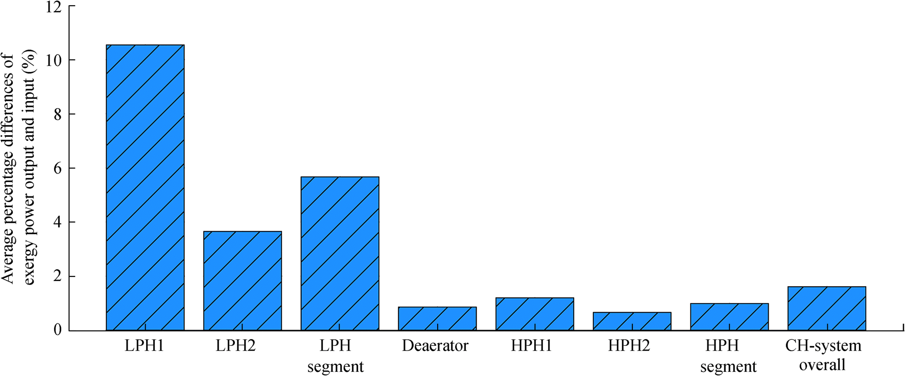 Figure 10 Average percentage difference of exergy power output and input for the condensate heating system, its segments, and components in the observed ambient temperature range
Further analysis, improvements and possible optimization of the marine condensate heating system will be performed using various artificial intelligence (AI) methods, algorithms, and techniques. Our research team has already successfully applied such AI methods in several marine systems (Lorencin et al. 2019b; Baressi Šegota et al. 2020), for electrical power output prediction of a complex combined cycle power plant (Lorencin et al. 2019c), and in various medical applications (Car et al. 2020; Lorencin et al. 2020). Therefore, we have enough reasons to believe that the abovementioned methods will be very useful in further investigations of the marine condensate heating system, its segments and components.
7 Conclusions
This paper presents a thermodynamic (energy and exergy) analysis of the condensate heating system, its segments, and components from a marine steam propulsion plant with steam reheating. It is found that energy analysis of any condensate heating system (not only of the observed one) should be avoided, because it can give unrealistic results caused by measurement equipment inaccuracy and imprecision. In the observed marine condensate heating system, the energy power losses related to any component did not exceed 3 kW, while the energy efficiencies were higher than 99%.
Exergy analysis of condensate heating systems is an effective evaluation approach. In the base ambient state, the deaerator from the analyzed system has a higher exergy efficiency and lower exergy destruction (95.96% and 70.74 kW, respectively) than those of all other heaters. In a properly balanced condensate heating system, exergy efficiencies of closed condensate heaters should continuously increase from the lowest to the highest steam pressure. In the analyzed system, exergy efficiencies of closed condensate heaters in the base ambient state continuously increase from 70.10% to 92.29%, while the exergy efficiency of the low pressure heating segment (75.34%) is much lower than that of the high pressure heating segment (89.63%). The entire observed condensate heating system has an exergy destruction of 559.41 kW and an exergy efficiency of 89.40% in the base ambient state.
Components and segments of the marine condensate heating system are not equally influenced by the ambient temperature change. The exergy efficiency of the closed condensate heater mounted nearest the main condenser is the most influenced by the ambient temperature change. In the performed analysis, a change in the ambient temperature from 5 to 45 ℃ causes an LPH1 exergy efficiency change of 31.61%, which is much higher than those of the other components. The ambient temperature change also has a notable influence on the exergy efficiency of the low pressure heating segment, whereas its influence on the exergy efficiency of the deaerator, high pressure heaters, and high pressure heating segment is slight.
The average percentage difference of exergy power output and input can be used as an effective measure in the ambient temperature influence evaluation for any component or segment or for the entire condensate heating system. In the analyzed system, an average percentage difference of exergy power output and input higher than 2% indicates a notable exergy efficiency change during the change in the ambient temperature and vice versa.
-
Figure 1 Scheme of the marine steam propulsion plant with steam reheating
Figure 2 Analyzed marine condensate heating system, its segments, and components
Figure 3 Energy efficiencies and destructions (losses) of the condensate heating system, its segments, and components
Figure 4 Exergy power inputs and outputs of the condensate heating system, its segments, and components (base ambient state)
Figure 5 Exergy efficiencies and destructions of the condensate heating system and its segments and components (base ambient state)
Figure 6 Exergy destruction of condensate heating system components during an ambient temperature change
Figure 7 Exergy efficiency of condensate heating system components during an ambient temperature change
Figure 8 Exergy destruction of the condensate heating system and its segments during an ambient temperature change
Figure 9 Exergy efficiency of the condensate heating system and its segments during the ambient temperature change
Figure 10 Average percentage difference of exergy power output and input for the condensate heating system, its segments, and components in the observed ambient temperature range
Table 1 Energy analysis equations of condensate heaters
Comp. Energy power input Energy power output Energy destruction (energy power loss) Energy efficiency LPH1 $ {\displaystyle \begin{array}{l}\overset{\cdot }{E}{n}_{\mathrm{IN},\mathrm{LPH}1}=\\ {}=\overset{\cdot }{E}{n}_{13}+\overset{\cdot }{E}{n}_{24}-\overset{\cdot }{E}{n}_{19}\end{array}} $ ${\displaystyle \begin{array}{l}\overset{\cdot }{E}{n}_{\mathrm{OUT},\mathrm{LPH}1}=\\ {}=\overset{\cdot }{E}{n}_{18}-\overset{\cdot }{E}{n}_{17}\end{array}} $ ${\displaystyle \begin{array}{l}\overset{\cdot }{E}{n}_{\mathrm{D},\mathrm{LPH}1}=\\ {}=\overset{\cdot }{E}{n}_{\mathrm{IN},\mathrm{LPH}1}-\overset{\cdot }{E}{n}_{\mathrm{OUT},\mathrm{LPH}1}\end{array}} $ ${\eta}_{\mathrm{I},\mathrm{LPH}1}=\frac{\overset{\cdot }{E}{n}_{\mathrm{OUT},\mathrm{LPH}1}}{\overset{\cdot }{E}{n}_{\mathrm{I}\mathrm{N},\mathrm{LPH}1}} $ LPH2 ${\displaystyle \begin{array}{l}\overset{\cdot }{E}{n}_{\mathrm{IN},\mathrm{LPH}2}=\\ {}=\overset{\cdot }{E}{n}_{12}-\overset{\cdot }{E}{n}_{23}\end{array}} $ ${\displaystyle \begin{array}{l}\overset{\cdot }{E}{n}_{\mathrm{OUT},\mathrm{LPH}2}=\\ {}=\overset{\cdot }{E}{n}_{22}-\overset{\cdot }{E}{n}_{21}\end{array}} $ ${\displaystyle \begin{array}{l}\overset{\cdot }{E}{n}_{\mathrm{D},\mathrm{LPH}2}=\\ {}=\overset{\cdot }{E}{n}_{\mathrm{IN},\mathrm{LPH}2}-\overset{\cdot }{E}{n}_{\mathrm{OUT},\mathrm{LPH}2}\end{array}} $ ${\eta}_{\mathrm{I},\mathrm{LPH}2}=\frac{\overset{\cdot }{E}{n}_{\mathrm{OUT},\mathrm{LPH}2}}{\overset{\cdot }{E}{n}_{\mathrm{I}\mathrm{N},\mathrm{LPH}2}} $ DEA $ {\displaystyle \begin{array}{l}\overset{\cdot }{E}{n}_{\mathrm{IN},\mathrm{DEA}}=\\ {}=\overset{\cdot }{E}{n}_{10}+\overset{\cdot }{E}{n}_{22}+\overset{\cdot }{E}{n}_{30}\end{array}}$ $\(\overset{\cdot }{E}{n}_{\mathrm{OUT}, \mathrm{DEA}}=\overset{\cdot }{E}{n}_{25} \) ${\displaystyle \begin{array}{l}\overset{\cdot }{E}{n}_{\mathrm{D},\mathrm{DEA}}=\\ {}=\overset{\cdot }{E}{n}_{\mathrm{IN},\mathrm{DEA}}-\overset{\cdot }{E}{n}_{\mathrm{OUT},\mathrm{DEA}}\end{array}} $ ${\eta}_{\mathrm{I},\mathrm{DEA}}=\frac{\overset{\cdot }{E}{n}_{\mathrm{OUT},\mathrm{DEA}}}{\overset{\cdot }{E}{n}_{\mathrm{I}\mathrm{N},\mathrm{DEA}}} $ HPH1 ${\displaystyle \begin{array}{l}\overset{\cdot }{E}{n}_{\mathrm{IN},\mathrm{HPH}1}=\\ {}=\overset{\cdot }{E}{n}_6+\overset{\cdot }{E}{n}_{32}-\overset{\cdot }{E}{n}_{29}\end{array}} $ ${\displaystyle \begin{array}{l}\overset{\cdot }{E}{n}_{\mathrm{OUT},\mathrm{HPH}1}=\\ {}=\overset{\cdot }{E}{n}_{27}-\overset{\cdot }{E}{n}_{26}\end{array}} $ ${\displaystyle \begin{array}{l}\overset{\cdot }{E}{n}_{\mathrm{D},\mathrm{HPH}1}=\\ {}=\overset{\cdot }{E}{n}_{\mathrm{IN},\mathrm{HPH}1}-\overset{\cdot }{E}{n}_{\mathrm{OUT},\mathrm{HPH}1}\end{array}} $ ${\eta}_{\mathrm{I},\mathrm{HPH}1}=\frac{\overset{\cdot }{E}{n}_{\mathrm{OUT},\mathrm{HPH}1}}{\overset{\cdot }{E}{n}_{\mathrm{I}\mathrm{N},\mathrm{HPH}1}} $ HPH2 ${\displaystyle \begin{array}{l}\overset{\cdot }{E}{n}_{\mathrm{IN},\mathrm{HPH}2}=\\ {}=\overset{\cdot }{E}{n}_4-\overset{\cdot }{E}{n}_{31}\end{array}} $ ${\displaystyle \begin{array}{l}\overset{\cdot }{E}{n}_{\mathrm{OUT},\mathrm{HPH}2}=\\ {}=\overset{\cdot }{E}{n}_{28}-\overset{\cdot }{E}{n}_{27}\end{array}} $ ${\displaystyle \begin{array}{l}\overset{\cdot }{E}{n}_{\mathrm{D},\mathrm{HPH}2}=\\ {}=\overset{\cdot }{E}{n}_{\mathrm{IN},\mathrm{HPH}2}-\overset{\cdot }{E}{n}_{\mathrm{OUT},\mathrm{HPH}2}\end{array}} $ ${\eta}_{\mathrm{I},\mathrm{HPH}2}=\frac{\overset{\cdot }{E}{n}_{\mathrm{OUT},\mathrm{HPH}2}}{\overset{\cdot }{E}{n}_{\mathrm{I}\mathrm{N},\mathrm{HPH}2}} $ Table 2 Energy analysis equations of the condensate heating system and its segments
Comp. Energy power input Energy power output Energy destruction (energy power loss) Energy efficiency LPHS ${\displaystyle \begin{array}{l}\overset{\cdot }{E}{n}_{\mathrm{IN},\mathrm{LPHS}}=\\ {}=\overset{\cdot }{E}{n}_{12}+\overset{\cdot }{E}{n}_{13}-\overset{\cdot }{E}{n}_{19}\end{array}} $ ${\displaystyle \begin{array}{l}\overset{\cdot }{E}{n}_{\mathrm{OUT},\mathrm{LPHS}}=\\ {}=\overset{\cdot }{E}{n}_{22}-\overset{\cdot }{E}{n}_{17}-\overset{\cdot }{E}{n}_{20}\end{array}} $ ${\displaystyle \begin{array}{l}\overset{\cdot }{E}{n}_{\mathrm{D},\mathrm{LPHS}}=\\ {}=\overset{\cdot }{E}{n}_{\mathrm{IN},\mathrm{LPHS}}-\overset{\cdot }{E}{n}_{\mathrm{OUT},\mathrm{LPHS}}\end{array}} $ ${\eta}_{\mathrm{I},\mathrm{LPHS}}=\frac{\overset{\cdot }{E}{n}_{\mathrm{OUT},\mathrm{LPHS}}}{\overset{\cdot }{E}{n}_{\mathrm{I}\mathrm{N},\mathrm{LPHS}}} $ HPHS ${\displaystyle \begin{array}{l}\overset{\cdot }{E}{n}_{\mathrm{IN},\mathrm{HPHS}}=\\ {}=\overset{\cdot }{E}{n}_4+\overset{\cdot }{E}{n}_6-\overset{\cdot }{E}{n}_{29}\end{array}} $ $\overset{\cdot }{E}{n}_{\mathrm{OUT},\mathrm{HPHS}}=\overset{\cdot }{E}{n}_{28}-\overset{\cdot }{E}{n}_{26} $ ${\displaystyle \begin{array}{l}\overset{\cdot }{E}{n}_{\mathrm{D},\mathrm{HPHS}}=\\ {}=\overset{\cdot }{E}{n}_{\mathrm{IN},\mathrm{HPHS}}-\overset{\cdot }{E}{n}_{\mathrm{OUT},\mathrm{HPHS}}\end{array}} $ ${\eta}_{\mathrm{I},\mathrm{HPHS}}=\frac{\overset{\cdot }{E}{n}_{\mathrm{OUT},\mathrm{HPHS}}}{\overset{\cdot }{E}{n}_{\mathrm{I}\mathrm{N},\mathrm{HPHS}}} $ CHS ${\displaystyle \begin{array}{l}\overset{\cdot }{E}{n}_{\mathrm{IN},\mathrm{CHS}}=\overset{\cdot }{E}{n}_{\mathrm{IN},\mathrm{LPHS}}+\\ {}+\overset{\cdot }{E}{n}_{\mathrm{IN},\mathrm{HPHS}}+\overset{\cdot }{E}{n}_{\mathrm{IN},\mathrm{DEA}}\end{array}} $ ${\displaystyle \begin{array}{l}\overset{\cdot }{E}{n}_{\mathrm{OUT},\mathrm{CHS}}=\overset{\cdot }{E}{n}_{\mathrm{OUT},\mathrm{LPHS}}+\\ {}+\overset{\cdot }{E}{n}_{\mathrm{OUT},\mathrm{HPHS}}+\overset{\cdot }{E}{n}_{\mathrm{OUT},\mathrm{DEA}}\end{array}} $ ${\displaystyle \begin{array}{l}\overset{\cdot }{E}{n}_{\mathrm{D},\mathrm{CHS}}=\\ {}=\overset{\cdot }{E}{n}_{\mathrm{IN},\mathrm{CHS}}-\overset{\cdot }{E}{n}_{\mathrm{OUT},\mathrm{CHS}}\end{array}} $ ${\eta}_{\mathrm{I},\mathrm{CHS}}=\frac{\overset{\cdot }{E}{n}_{\mathrm{OUT},\mathrm{CHS}}}{\overset{\cdot }{E}{n}_{\mathrm{I}\mathrm{N},\mathrm{CHS}}} $ Table 3 Thermodynamic data of required fluid streams
Operating point* Stream mass flow rate (kg/s) Stream pressure (kPa) Stream temperature (℃) Stream specific enthalpy (kJ/kg) Stream specific entropy (kJ/kg·K) Stream specific exergy at the base ambient state (kJ/kg) 4 1.055 3 770 397.26 3 211.70 6.793 1 256.02 6 1.679 2 120 325.46 3 079.20 6.837 1 111.01 10 0.421 520 341.56 3 149.80 7.587 965.37 12 0.808 240 249.92 2 969.40 7.623 774.63 13 0.683 60 126.97 2 734.10 7.746 503.93 17 10.947 520 42.80 179.06 0.607 5.69 18 10.947 520 81.23 339.75 1.088 28.09 19 1.491 60 85.93 359.10 1.144 31.43 20 1.491 520 85.98 359.86 1.144 31.93 21 12.438 520 81.80 342.31 1.095 28.54 22 12.438 520 119.37 500.65 1.519 64.75 23 0.808 240 126.07 528.99 1.591 72.23 24 0.808 60 85.93 528.99 1.616 64.97 25 15.593 520 153.32 645.87 1.874 107.74 26 15.593 10 300 155.03 659.20 1.880 119.28 27 15.593 10 300 210.35 901.55 2.412 208.33 28 15.593 10 300 241.87 1 046.45 2.703 269.56 29 2.734 2 120 215.35 921.45 2.473 210.75 30 2.734 520 153.32 921.45 2.520 197.13 31 1.055 3 770 246.87 1 069.90 2.764 275.44 32 1.055 2 120 215.35 1 069.90 2.777 271.57 *Operating point numeration refers to Figure 2 -
Abdella MM, Nassar IA (2019) Parameters calculation of thermal power plant dynamic model using steam cycle data. Thermal Science and Engineering Progress 9: 259–265. https://doi.org/10.1016/j.tsep.2018.11.014 Adamkiewicz A, Grzesiak S (2019) Identification of waste heat energy sources of a conventional steam propulsion plant of an LNG carrier. Archives of Thermodynamics 40(3): 195–210. https://doi.org/10.24425/ather.2019.130001 Adeli J, Niknejadi M, Toghraie D (2020) Full repowering of an existing fossil fuel steam power plant in terms of energy, exergy, and environmen for efficiency improvement and sustainable development. Environment, Development and Sustainability 22(6): 5965–5999. https://doi.org/10.1007/s10668-019-00461-x Adibhatla S, Kaushik SC (2017a) Energy, exergy, economic and environmental (4E) analyses of a conceptual solar aided coal fired 500 MWe thermal power plant with thermal energy storage option. Sustainable Energy Technologies and Assessments 21: 89–99. https://doi.org/10.1016/j.seta.2017.05.002 Adibhatla S, Kaushik SC (2017b) Exergy and thermoeconomic analyses of 500 MWe sub critical thermal power plant with solar aided feed water heating. Applied Thermal Engineering 123: 340–352. https://doi.org/10.1016/j.applthermaleng.2017.05.099 Ahmadi GR, Toghraie D (2016) Energy and exergy analysis of Montazeri Steam Power Plant in Iran. Renewable and Sustainable Energy Reviews 56: 454–463. https://doi.org/10.1016/j.rser.2015.11.074 Ahmadi G, Toghraie D, Akbari OA (2018) Technical and environmental analysis of repowering the existing CHP system in a petrochemical plant: a case study. Energy 159: 937–949. https://doi.org/10.1016/j.energy.2018.06.208 Aljundi IH (2009) Energy and exergy analysis of a steam power plant in Jordan. Applied Thermal Engineering 29: 324–328. https://doi.org/10.1016/j.applthermaleng.2008.02.029 Ameri M, Ahmadi P, Hamidi A (2009) Energy, exergy and exergoeconomic analysis of a steam power plant: a case study. International Journal of Energy Research 33: 499–512. https://doi.org/10.1002/er.1495 Baressi Šegota S, Lorencin I, Musulin J, Štifanić D, Car Z (2020) Frigate speed estimation using CODLAG propulsion system parameters and multilayer perceptron. The Our Sea, International Journal of Maritime Science & Technology 67(2): 117–125. https://doi.org/10.17818/NM/2020/2.4 Blažević S, Mrzljak V, Anđelić N, Car Z (2019) Comparison of energy flow stream and isentropic method for steam turbine energy analysis. Acta Polytechnica 59(2): 109–125. https://doi.org/10.14311/AP.2019.59.0109 Car Z, Baressi Šegota S, Anđelić N, Lorencin I, Mrzljak V (2020) Modeling the spread of COVID-19 infection using a multilayer perceptron. Computational and Mathematical Methods in Medicine 2020: 1–10. https://doi.org/10.1155/2020/5714714 Chauhan SS, Khanam S (2019) Enhancement of efficiency for steam cycle of thermal power plants using process integration. Energy 173: 364–373. https://doi.org/10.1016/j.energy.2019.02.084 Chen W, Zhang G, Li B, Liu M, Liu J (2017a) Simulation study on 660 MW coal-fired power plant coupled with a steam ejector to ensure NOx reduction ability. Applied Thermal Engineering 111: 550–561. https://doi.org/10.1016/j.applthermaleng.2016.09.104 Chen C, Zhou Z, Bollas GM (2017b) Dynamic modeling, simulation and optimization of a subcritical steam power plant. Part I: Plant model and regulatory control. Energy Conversion and Management 145: 324–334. https://doi.org/10.1016/j.enconman.2017.04.078 Cherednichenko O, Serbin S (2018) Analysis of efficiency of the ship propulsion system with thermochemical recuperation of waste heat. Journal of Marine Science and Application 17(1): 122–130. https://doi.org/10.1007/s11804-018-0012-x Elhelw M, Al Dahma KS, Hamid Attia AE (2019) Utilizing exergy analysis in studying the performance of steam power plant at two different operation mode. Applied Thermal Engineering 150: 285–293. https://doi.org/10.1016/j.applthermaleng.2019.01.003 Erdem HH, Akkaya AV, Cetin B, Dagdas A, Sevilgen SH, Sahin B, Teke I, Gungor C, Atas S (2009) Comparative energetic and exergetic performance analyses for coal-fired thermal power plants in Turkey. International Journal of Thermal Sciences 48(11): 2179–2186. https://doi.org/10.1016/j.ijthermalsci.2009.03.007 Fernández IA, Gómez MR, Gómez JR, Insua AAB (2017) Review of propulsion systems on LNG carriers. Renewable and Sustainable Energy Reviews 67: 1395–1411. https://doi.org/10.1016/j.rser.2016.09.095 Fulger M, Lucan D, Mihalache M, Velciu L (2019) Factors involved in stress corrosion cracking of tubes from a nuclear power plant feedwater heater. Revista de Chimie 70(11): 3926–3930. https://doi.org/10.37358/RC.19.11.7674 Geete A (2020) Performance analyses of coal-fired thermal power plant using parabolic solar collectors for feed water heaters. Australian Journal of Mechanical Engineering: 1–12. https://doi.org/10.1080/14484846.2019.1706226 Hoseinzadeh S, Heyns PS (2020) Thermo-structural fatigue and lifetime analysis of a heat exchanger as a feedwater heater in power plant. Engineering Failure Analysis 113: 104548. https://doi.org/10.1016/j.engfailanal.2020.104548 Kamil Mohammed M, Al Doori WH, Jassim AH, Ibrahim TK, Al-Sammarraie AT (2019) Energy and exergy analysis of the steam power plant based on effect the numbers of feed water heater. Journal of Advanced Research in Fluid Mechanics and Thermal Sciences 56(2): 211–222 Kanoğlu M, Çengel YA, Dinçer İ (2012) Efficiency evaluation of energy systems. Springer Briefs in Energy, Springer. https://doi.org/10.1007/978-1-4614-2242-6 Kaushik SC, Reddy VS, Tyagi SK (2011) Energy and exergy analyses of thermal power plants: a review. Renewable and Sustainable Energy Reviews 15:1857–1872. https://doi.org/10.1016/j.rser.2010.12.007 Khan MS, Abid M, Ratlamwala TAH (2019) Energy, exergy and economic feasibility analyses of a 60 MW conventional steam power plant integrated with parabolic trough solar collectors using nanofluids. Iranian Journal of Science and Technology, Transactions of Mechanical Engineering 43(1): 193–209. https://doi.org/10.1007/s40997-018-0149-x Kocijel L, Poljak I, Mrzljak V, Car Z (2020) Energy loss analysis at the gland seals of a marine turbo-generator steam turbine. Technical Journal 14(1): 19–26. https://doi.org/10.31803/tg-20191031094436 Kopac M, Hilalci A (2007) Effect of ambient temperature on the efficiency of the regenerative and reheat Catalagzi power plant in Turkey. Applied Thermal Engineering 27:1377–1385. https://doi.org/10.1016/j.applthermaleng.2006.10.029 Koroglu T, Sogut OS (2018) Conventional and advanced exergy analyses of a marine steam power plant. Energy 163:392–403. https://doi.org/10.1016/j.energy.2018.08.119 Kowalczyk T, Badur J, Bryk M (2019) Energy and exergy analysis of hydrogen production combined with electric energy generation in a nuclear cogeneration cycle. Energy Conversion and Management 198:111805. https://doi.org/10.1016/j.enconman.2019.111805 Kumar R, Sharma AKR, Tewari PC (2014) Thermal performance and economic analysis of 210 MWe coal-fired power plant. Journal of Thermodynamics: 520183. https://doi.org/10.1155/2014/520183 Kumar S, Kumar D, Memon RA, Wassan MA, Ali MS (2018) Energy and exergy analysis of a coal fired power plant. Mehran University Research Journal of Engineering & Technology 37(4): 611–624. https://doi.org/10.22581/muet1982.1804.13 Lamas Galdo MI, Castro-Santos L, Rodriguez Vidal CG (2020) Numerical analysis of NOx reduction using ammonia injection and comparison with water injection. Journal of Marine Science and Engineering 8(2): 109. https://doi.org/10.3390/jmse8020109 Lemmon EW, Huber ML, McLinden MO (2010) NIST reference fluid thermodynamic and transport properties—REFPROP, version 9.0, User's guide, Colorado, USA. Li J, Wu Z, Zeng K, Flamant G, Ding A, Wang J (2017) Safety and efficiency assessment of a solar-aided coal-fired power plant. Energy Conversion and Management 150:714–724. https://doi.org/10.1016/j.enconman.2017.08.049 Lorencin I, Anđelić N, Mrzljak V, Car Z (2019a) Exergy analysis of marine steam turbine labyrinth (gland) seals. Scientific Journal of Maritime Research 33(1): 76–83. https://doi.org/10.31217/p.33.1.8 Lorencin I, Anđelić N, Mrzljak V, Car Z (2019b) Marine objects recognition using convolutional neural networks. International Journal of Maritime Science & Technology "Our Sea" 66(3): 112–119. https://doi.org/10.17818/NM/2019/3.3 Lorencin I, Anđelić N, Mrzljak V, Car Z (2019c) Genetic algorithm approach to design of multi-layer perceptron for combined cycle power plant electrical power output estimation. Energies 12(22): 4352. https://doi.org/10.3390/en12224352 Lorencin I, Anđelić N, Šegota SB, Musulin J, Štifanić D, Mrzljak V, Španjol J, Car Z (2020) Edge detector-based hybrid artificial neural network models for urinary bladder cancer diagnosis. In: Enabling AI Applications in Data Science. Springer, Cham, pp 225–245. https://doi.org/10.1007/978-3-030-52067-0_10 Medica-Viola V, Baressi Šegota S, Mrzljak V, Štifanić D (2020a) Comparison of conventional and heat balance based energy analyses of steam turbine. Scientific Journal of Maritime Research 34(1): 74–85. https://doi.org/10.31217/p.34.1.9 Medica-Viola V, Mrzljak V, Anđelić N, Jelić M (2020b) Analysis of low-power steam turbine with one extraction for marine applications. International Journal of Maritime Science & Technology 67(2): 87–95. https://doi.org/10.17818/NM/2020/2.1 Mrzljak V, Poljak I (2019) Energy analysis of main propulsion steam turbine from conventional LNG carrier at three different loads. International Journal of Maritime Science & Technology "Our Sea" 66(1): 10–18. https://doi.org/10.17818/NM/2019/1.2 Mrzljak V, Poljak I, Medica-Viola V (2017a) Dual fuel consumption and efficiency of marine steam generators for the propulsion of LNG carrier. Applied Thermal Engineering 119:331–346. https://doi.org/10.1016/j.applthermaleng.2017.03.078 Mrzljak V, Poljak I, Mrakovčić T (2017b) Energy and exergy analysis of the turbo-generators and steam turbine for the main feed water pump drive on LNG carrier. Energy Conversion and Management 140:307–323. https://doi.org/10.1016/j.enconman.2017.03.007 Mrzljak V, Blecich P, Anđelić N, Lorencin I (2019) Energy and exergy analyses of forced draft fan for marine steam propulsion system during load change. Journal of Marine Science and Engineering 7(11): 381. https://doi.org/10.3390/jmse7110381 Naserabad SN, Mehrpanahi A, Ahmadi G (2019) Multi-objective optimization of feed-water heater arrangement options in a steam power plant repowering. Journal of Cleaner Production 220:253–270. https://doi.org/10.1016/j.jclepro.2019.02.125 Naserbegi A, Aghaie M, Minuchehr A, Alahyarizadeh G (2018) A novel exergy optimization of Bushehr nuclear power plant by gravitational search algorithm (GSA). Energy 148:373–385. https://doi.org/10.1016/j.energy.2018.01.119 Noroozian A, Mohammadi A, Bidi M, Ahmadi MH (2017) Energy, exergy and economic analyses of a novel system to recover waste heat and water in steam power plants. Energy Conversion and Management 144:351–360. https://doi.org/10.1016/j.enconman.2017.04.067 Oyedepo SO, Fakeye BA, Mabinuori B, Babalola PO, Leramo RO, Kilanko O, Dirisu JO, Udo M, Efemwenkiekie UK, Oyebanji JA (2020) Thermodynamics analysis and performance optimization of a reheat–Regenerative steam turbine power plant with feed water heaters. Fuel 280:118577. https://doi.org/10.1016/j.fuel.2020.118577 Poljak I, Bielić T, Mrzljak V, Orović J (2020) Analysis and Optimization of Atmospheric Drain Tank of LNG Carrier Steam Power Plant. Journal of Marine Science and Engineering 8(8): 568. https://doi.org/10.3390/jmse8080568 Prasad Sinha R, Balaji R (2018) A mathematical model of marine diesel engine speed control system. Journal of the Institution of Engineers (India): Series C 99(1): 63–70. https://doi.org/10.1007/s40032-017-0420-8 Ramesh M, Manavalan S (2019) Failure analysis in high pressure feed water heaters and method to find the defect in tubes. International Journal of Psychosocial Rehabilitation 23(3): 422–438. https://doi.org/10.37200/IJPR/V23I3/PR190140 Ray TK, Datta A, Gupta A, Ganguly R (2010) Exergy-based performance analysis for proper O & M decisions in a steam power plant. Energy Conversion and Management 51:1333–1344. https://doi.org/10.1016/j.enconman.2010.01.012 Rocha DHD, Silva RJ (2019) Exergoenvironmental analysis of a ultra-supercritical coal-fired power plant. Journal of Cleaner Production 231:671–682. https://doi.org/10.1016/j.jclepro.2019.05.214 Senčić T, Mrzljak V, Blecich P, Bonefačić I (2019) 2D CFD simulation of water injection strategies in a large marine engine. Journal of Marine Science and Engineering 7:296. https://doi.org/10.3390/jmse7090296) Song C, Zhu C, Liu H, Ni G (2015) Dynamic analysis and experimental study of a marine gearbox with crossed beveloid gears. Mechanism and Machine Theory 92:17–28. https://doi.org/10.1016/j.mechmachtheory.2015.05.001 Tan H, Shan S, Nie Y, Zhao Q (2018) A new boil-off gas re-liquefaction system for LNG carriers based on dual mixed refrigerant cycle. Cryogenics 92:84–92. https://doi.org/10.1016/j.cryogenics.2018.04.009 Uysal C, Kurt H, Kwak Y (2017) Exergetic and thermoeconomic analyses of a coal-fired power plant. International Journal of Thermal Sciences 117:106–120. https://doi.org/10.1016/j.ijthermalsci.2017.03.010 Wijaya AA, Widodo BUK (2019) The effect of feedwater heaters operation schemes to a 200 MW steam power plant heat rate using cycle-tempo software. IPTEK The Journal of Engineering 4(3): 33–37. https://doi.org/10.12962/j23378557.v4i3.a4995 Woodruff E, Lammers H, Lammers T (2004) Steam plant operation, 8th edn. McGraw-Hill Professional, New York, NY, USA Zangeneh S, Bakhtiari R (2019) Failure investigation of a deaerating feed-water heater in a power plant. Engineering Failure Analysis 101:145–156. https://doi.org/10.1016/j.engfailanal.2019.03.007 Zhao Z, Su S, Si N, Hu S, Wang Y, Xu J, Jiang L, Chen G, Xiang J (2017) Exergy analysis of the turbine system in a 1000 MW double reheat ultra-supercritical power plant. Energy 119:540–548. https://doi.org/10.1016/j.energy.2016.12.072 Zhao Y, Wang C, Liu M, Chong D, Yan J (2018) Improving operational flexibility by regulating extraction steam of high-pressure heaters on a 660 MW supercritical coal-fired power plant: a dynamic simulation. Applied Energy 212:1295–1309. https://doi.org/10.1016/j.apenergy.2018.01.017 Zhao Y, Fan P, Wang C, Liu M, Chong D, Yan J (2019) Fatigue lifetime assessment on a high-pressure heater in supercritical coal-fired power plants during transient processes of operational flexibility regulation. Applied Thermal Engineering 156:196–208. https://doi.org/10.1016/j.applthermaleng.2019.04.066)