A Practical Specialization of MDA/MBSE Approach to Develop AUV Controllers
https://doi.org/10.1007/s11804-020-00151-5
-
Abstract
The model-driven architecture (MDA)/model-based systems engineering (MBSE) approach, in combination with the real-time Unified Modeling Language (UML)/Systems Modeling Language (SysML), unscented Kalman filter (UKF) algorithm, and hybrid automata, are specialized to conveniently analyze, design, and implement controllers of autonomous underwater vehicles (AUVs). The dynamics and control structure of AUVs are adapted and integrated with the specialized features of the MDA/MBSE approach as follows. The computation-independent model is defined by the specification of a use case model together with the UKF algorithm and hybrid automata and is used in intensive requirement analysis. The platform-independent model (PIM) is then built by specializing the real-time UML/SysML's features, such as the main control capsules and their dynamic evolutions, which reflect the structures and behaviors of controllers. The detailed PIM is subsequently converted into the platform-specific model by using open-source platforms to quickly implement and deploy AUV controllers. The study ends with a trial trip and deployment results for a planar trajectory-tracking controller of a miniature AUV with a torpedo shape.Article Highlights• A specialization of MDA/MBSE approach combined with the UKF algorithm and hybrid automata is performed to systematically analyze, design and implement an AUV controller.• A planar trajectory-tracking controller of a miniature torpedo-shaped AUV was deployed and tested.• The designed capsule collaboration of real-time UML/SysML can be customized and reused for new control applications of various AUV types. -
1 Introduction
Autonomous underwater vehicles (AUVs) have been widely developed and used for the study of oceans to enhance the cost-effectiveness of civil society and improve existing naval facilities, e.g., the biological discovery of ocean resources, disaster and tsunami warnings, and self-operated underwater military means (Allotta et al. 2016b; Brignone et al. 2015; Cui 2019; Ribas et al. 2015; Shojaei and Dolatshahi 2017; Wynn et al. 2014).
In the present design and construction of AUV controllers, traditional guidance, navigation, and control methods are combined with soft computing techniques to closely deal with the control of AUV dynamics (Allotta et al. 2016a; Bhopale et al. 2019; Eslami et al. 2018; MahmoudZadeh et al. 2018). For example, Shariati et al. (2019) applied a particle filter combined with an extended Kalman filter (EKF) to the model identification of AUVs so as to minimize the errors and variances of nonlinear control systems for AUVs. A hierarchical robust nonlinear (HRN) controller was designed by Karkoub et al. (2017) for the trajectory tracking of an AUV subject to uncertainties (e.g., current disturbances, unmodeled dynamics, and parameter variations); the proposed HRN controller utilizes the backstepping and sliding mode control technique with a hierarchical structure based on the kinematic and dynamic models of the system. The robustness of the proposed HRN controller was then verified through injection of random uncertainties into the system model. The closed-loop stability of the proposed individual subsystems is guaranteed to have uniformly ultimately bounded performance according the Lyapunov stability criteria. Shojaei and Dolatshahi (2017) introduced the target tracking control of underactuated AUVs in the presence of model uncertainties and environmental disturbances. In this study, dynamic surface control, neural networks, and adaptive control techniques were employed to develop a target-tracking controller for underwater vehicles in a three-dimensional space; a Lyapunov-based stability analysis proved that all signals are bounded in the closed-loop control system and that tracking errors converge to a neighborhood of the origin.
In fact, customization and reusability are factors associated with the production of new applications to reduce costs, resources, and time development. According to the Object Management Group (OMG) (OMG 2015), the Unified Modeling Language (UML) is essential for its visual object-oriented design support and has been increasingly utilized and appreciated in the software industry. The System Modeling Language (SysML) (OMG 2017), which is a UML profile for systems engineering, has been standardized by OMG. SysML supports the specification, analysis, design, verification, and validation of a broad range of complex systems. However, UML and SysML lack constructs for modeling the time and duration constraints of developed systems. OMG have standardized the model-driven architecture (MDA) (OMG 2014) so as to separate the specification of system operations from the details pertaining to the way that a system uses the capabilities of its platform. The three main goals of MDA are portability, interoperability, and reusability through the architectural separation of concerns. Portability allows the same solution to be realized on new or multiple platforms. Interoperability creates systems that can easily integrate and communicate with other systems and use a variety of resource applications. Reusability builds solutions that can be reused in many different applications in different contexts. Model-based systems engineering (MBSE) is the formalized application of modeling to support system requirements and design, analysis, verification, and validation activities starting from the conceptual design phase and continuing throughout the development and later life cycle phases (INCOSE 2007; INCOSE 2014). MBSE is intended to facilitate systems engineering activities that have traditionally been performed using the document-based approach. It is expected to result in enhanced specification and design quality, enable the reuse of system specification and design artifacts, and facilitate communication among development teams. The output of systems engineering activities is a coherent model of the system, with the emphasis placed on evolving and refining the model using model-based methods and tools. For example, Sakairi et al. (2013) presented the integration of a SysML modeling tool (IBM Rational Rhapsody (IBM 2018)) with a proprietary simulation tool (MathWorks Simulink (MathWorks 2018)) and a computer algebra system (CAS), which was mainly based on MBSE concepts, to validate system specification. The integration with Simulink enables users to implement systems engineering processes in the SysML model while designing continuous control algorithms and plant behavior in Simulink. Plant behavior can also be validated by simulating the overall composition in Simulink. The integration with the CAS enables the evaluation of mathematical constraints defined in SysML parametric diagrams. Hence, MDA is a system development paradigm that emphasizes the use of rigorous visual modeling techniques throughout the system development life cycle, and MBSE is a specialization of MDA that applies MDA principles and best practices to systems engineering applications (Hien et al. 2018; Soriano et al. 2016).
The features of MDA/MBSE can thus be specialized together with the real-time UML/SysML (Douglass 2014; OMG 2011, 2017; Selic and Gerard 2014) to model in detail the analysis and design artifacts for real-time and embedded control systems, e.g., AUV controllers.
On the basis of the aforementioned points, this study is interested in implementing a control model that integrates AUV dynamics into MDA/MBSE combined with real-time object paradigms, the unscented Kalman filter (UKF) algorithm, and the specialization of hybrid automata (HA) features. This model facilitates the realization and deployment of AUV controllers and makes the designed and implemented control elements to be closely customizable and reusable in the realization of new control applications for various AUV types. In this model, the dynamics and control structure of AUVs are adapted for control and are then combined with the specialization of MDA/MBSE features, including the computation-independent model (CIM), platform-independent model (PIM), and platform-specific model (PIM). The control system permits an AUV to track a horizontal planar reference path in the Cartesian space. Herein, the CIM includes a use case model that is specialized closely with an implementable function block diagram, the supplemented UKF algorithm, and HA to precisely achieve the requirement analysis of control for AUV controllers. The PIM is built on the identified CIM by specifying the real-time UML/SysML to intensively design real-time control capsules with ports, protocols, and intercommunication evolution for AUV controllers. The detailed PIM elements are then converted into platform-specific models (PSMs) by using open-source platforms, such as OpenModelica (OpenModelica 2018) and Arduino (Arduino 2018), to quickly simulate, realize, and deploy AUV controllers. A horizontal planar trajectory-tracking controller for a miniature AUV (M-AUV) with a torpedo shape was completely deployed and tested.
This paper is structured as follows. The adapted dynamics and control structure of AUVs are introduced in Section 2. The details of model-driven development aimed at intensively realizing AUV controllers, including the CIM, PIM, and PSM components, are provided in Section 3. The application of the specialized model to a case study is discussed in Section 4. Conclusions and future works are reported in Section 5.
2 Adapting AUV Dynamics and Control Structure
2.1 Overview of AUV Dynamics for Control
According to SNAME (1950), the six motion components of an underwater vehicle are surge, sway, heave, roll, pitch, and yaw (Table 1).
Table 1 SNAME notations for underwater vehiclesDegree of freedom Motions Force and moment Linear and angular velocity Position and Euler angles 1 Surge X u x 2 Sway Y v y 3 Heave Z w z 4 Roll K p ϕ 5 Pitch M q θ 6 Yaw N r ψ Based on the guidance, navigation, and control of underwater vehicles, the 6 DoF dynamic model of AUVs in body frame (Antonelli 2006; Fossen 2002, 2011; Lantos and Márton 2011) can be written as follows:
$$ \left\{\begin{array}{l}\dot{\eta}=J\left(\eta \right)\nu \kern5em \\ {}M\dot{\nu}+C\left(\nu \right)\nu +D\left(\nu \right)\nu +g\left(\eta \right)=\tau \left(v,\mathrm{u}\right)\end{array}\right. $$ (1) where η = [η1T, η2T]T includes the position η1 = [x, y, z]T (NED: north, east, and down) and the orientation η2 = [ϕ, θ, ψ]T (Euler RPY: roll, pitch, and yaw angles); ν = [v1T, v2T]T comprises the linear v1 = [u, v, w]T and the angular v2 = [p, q, r]T velocities; M = MRB + MA is a mass matrix that denotes the 6 × 6 system inertia matrix containing the generalized constant inertia matrix MRB and the added mass inertia matrix MA; C(ν) = CRB(ν) + CA(ν) is the 6 × 6 coriolis and centripetal force matrix with added mass; the 6 × 6 matrix D(ν) = D + Dn(ν) contains linear and nonlinear hydrodynamic damping, with D containing the linear damping terms and Dn(ν) containing the nonlinear damping terms; g(η) is the 6 × 1 vector of gravitational and buoyancy effects; τ(v, u) is the vector of resultant force and moment acting on the underwater vehicle; and u denotes the control inputs, e.g., the rotational speed of the motors related to the generated thrusts and the driving angles sent to the needed servomotor for sail planes and rudder.
A discrete state-space representation is required in modeling AUV controllers based on a recursive digital motion estimation filter (Allotta et al. 2016a), e.g., the UKF; the developed system can then be described by the following set of equations:
$$ \left\{\begin{array}{c}{x}_k={f}_{k-1}\left({x}_{k-1},{u}_{k-1}\right)+{w}_{k-1}\\ {}{y}_k={h}_k\left({x}_k\right)+{v}_k\kern2.25em \end{array}\right. $$ (2) Here, $ x=\left[\begin{array}{c}\eta \\ {}\nu \end{array}\right] $ is a 12-dimensional state vector for describing AUV motion and xk is the vector of state variables at the kth instant of x; uk and yk, respectively, denote the inputs and outputs of the system; hk, wk, and vk are the measurement function, additive process, and measurement noise, respectively. The first equation in (2) is called the system's evolution equation while the second one is called the measurement equation.
On the basis of the AUV dynamic model (1), the following assumptions are made: as the AUV drag along transversal directions strongly dampens the lateral and vertical motions, the AUV dynamics can be considered to take place only in the longitudinal direction. The time evolution of the developed system is then written in the following equations:
$$ {\displaystyle \begin{array}{l}\dot{x}=\left[\begin{array}{c}\dot{\eta}\\ {}\dot{v}\end{array}\right]=F\left(x,u\right)+w=\\ {}\left(\begin{array}{c}\dot{\eta}=J\left({\eta}_2\right)\nu \\ {}{M}^{-1}\left(\tau \left(v,u\right)-C\left(\nu \right)\nu -D\left(\nu \right)\nu -g\left(\eta \right)\right)\end{array}\right)+w\end{array}} $$ (3) 2.2 Control Structure of an AUV
Three main systems comprise the autonomy architecture of AUVs: the guidance system responsible for generating the trajectory to be followed by the AUV, the navigation system that estimates the current state of the vehicle, and the control system that calculates and applies appropriate forces to maneuver the vehicle. All these subsystems have corresponding tasks to complete, but they must also work cooperatively to ensure that the AUV completes its objectives even in the presence of unknown environmental disturbances. Figure 1 shows a general block definition diagram in SysML, which captures how these subsystems interact.
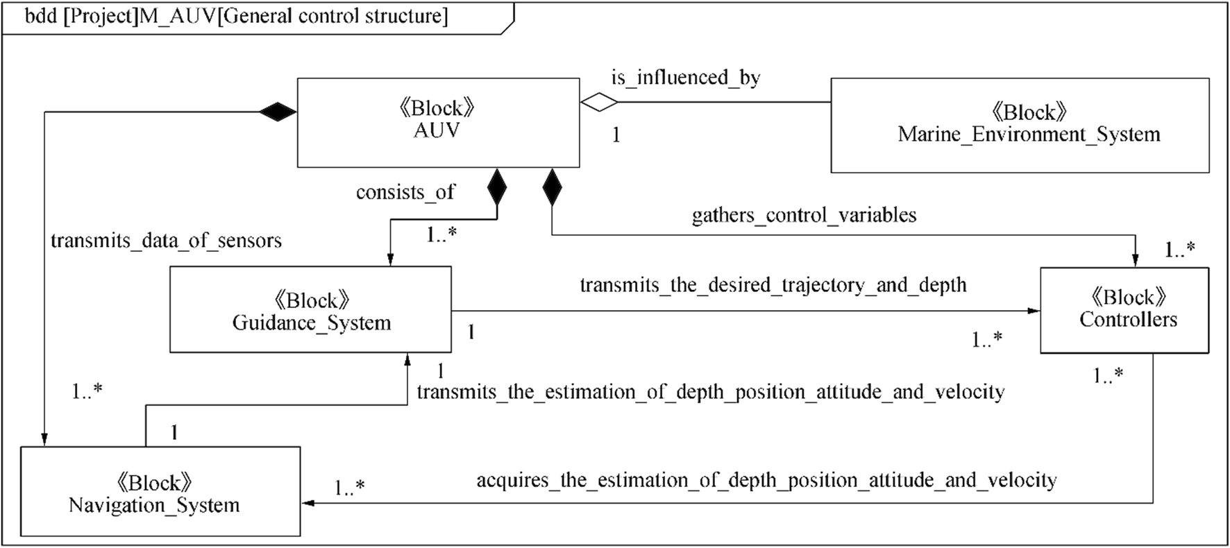 Figure 1 General control architecture for an AUV
The problem of control design for AUVs is equally challenging because controllers are closely connected to dynamic AUV models. Therefore, control systems must consider models with discrete events and continuous behaviors; such systems are called hybrid dynamic systems (HDS) (Carloni et al. 2006; Fishwick 2007). Control systems do not always have the same behavior because they are associated with validity hypotheses to be checked at any moment, security requirement forces to envisage events, and behaviors different from nominal behaviors. Hence, the behaviors of such systems are complex and can be modeled by HA (Fishwick 2007; Henzinger et al. 1998). On the basis of the description of the dynamics and general control structure of AUVs, together with the characteristics of HDS, one can consider AUV controllers as HDS. These controllers have continuous/discrete parts and interactions such as the surge, sway, heave, roll, pitch, and yaw motions. They are also prone to external interaction events from guidance and navigation systems and environmental disturbances. In the current model, the objective is to develop a trajectory-tracking controller for AUVs. The hybrid dynamic model is expected to be capable of identifying control algorithms combined with a specific guidance law, such as the line-of-sight (LOS) guidance (Lekkas and Fossen 2014; Shojaei and Dolatshahi 2017; Zheng and Zou 2016).
3 Specializing MDA/MBSE Features to Develop AUV Controllers
3.1 Building the CIM for an AUV Controller
The goal of the CIM is to entirely model a problem in business terms without delving into the solution or its implementation. In the CIM, object collaborations with real-time UML/SysML, which are based on the use case model; interaction diagrams; and state machines are used to describe the structure and behavior of an AUV controller.
Following the dynamics and control structure of AUVs adapted in Section 2 and together with LOS guidance, we present here the main use case model (Figure 2) of AUV controllers. We also provide an example of trajectory tracking scenarios and the local state machine of the "track a desired trajectory" use case (Figure 3a and b, respectively). In Figure 3(a), the "loop (5)" fragment is typical value in the practice of LOS guidance (Lantos and Márton 2011).
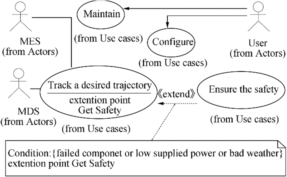 Figure 2 Main use case model for the AUV controller
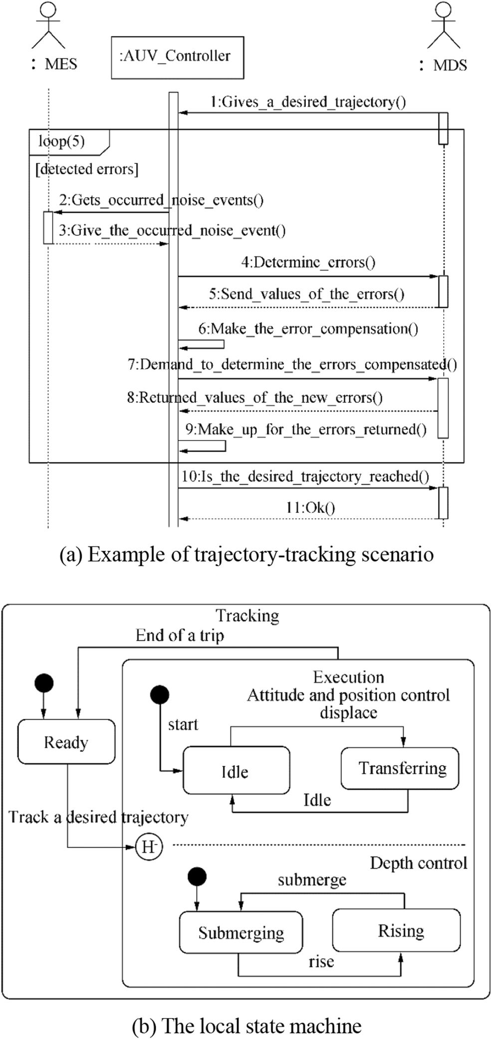 Figure 3 Dynamic behaviors of the "Track a desired trajectory" use case
In Figure 2, the actors of the developed AUV in the case study are described as follows:
• MDS is the measurement cum display system consisting of guidance and navigation systems that essentially act as signal suppliers for the AUV controller.
• MES is the marine environment system, which includes disturbances such as wind, waves, and ocean currents.
• User is a person who is responsible for verifying the physical properties of the AUV and configuring the system parameters for starting up missions of the AUV.
The use cases for the developed AUV are described as follows:
• The “Track a desired trajectory” use case is aimed at tracking the desired trajectory to be followed by the vehicle.
• The “Ensure safety” use case is aimed at ensuring system safety when one component fails, the supplied power is low, or the weather is poor.
• The “Configure” use case permits a user to configure and update control parameters for starting up missions of the AUV.
• The “Maintain” use case is aimed at maintaining the whole system, including its activities such as error identification and correction for the entire physical AUV and periodic maintenance.
In this model, all industrial conditions, e.g., the maximum swing angles of rudder and sail planes, velocity, immersible depth, and additional safe trip modes of the AUV being developed, should be provided to ensure the operational safety of the system.
An implemented functional block diagram must also be defined to model the continuous behaviors of the system amid external events because the real-time UML/SysML lacks constructs for modeling internal continuous behaviors for each state on the state machine diagram. Considering the dynamic model of AUVs, its industrial constraint conditions, and the defined use case model, we develop an implemented functional block diagram of an AUV controller, as shown in Figure 4 (Hien et al. 2018). Here, the desired trajectory and depth actions respectively provide the desired position (xd, yd) and depth (zd) to the position and deep controller. ΣTd is the desired overall thrust. The position controller receives the AUV's position (x, y) and desired thrust and outputs the desired roll (ϕd) and pitch (θd). The desired yaw (Ψd) comes directly from the guidance system block. The attitude controller gives the desired control signals to the actuator commands (e.g., Ωdi can be the desired motor speed sent to the main motor controllers for the propellers or tunnel thrusters or the desired driving steps sent to the needed servomotor controllers for sail planes, rudder, and displacement units; $ i={1,\mathrm{n}} $ for an AUV operating with n actuators, and thus, u is the control input of size n × 1). The proportional–integral–derivative (PID) regulators can be applied to the motor control block, including the main motor controllers and servomotor controllers, to reduce the inertial and delay time caused by the physical AUV actuators in the whole system evolution. τϕ, θ, Ψ and ΣT are the overall moment and force acting on the AUV, respectively. In the current model, the integral backstepping (IB) techniques implemented in previous works (Fossen 2011; Lantos and Márton 2011; Li et al. 2014) are hierarchically used to control the depth, position, and attitude of the AUV.
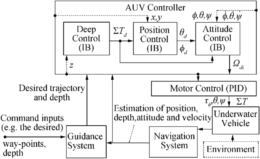 Figure 4 Implemented functional block diagram for the AUV controller
The state-space models (2) and (3) described in Section 2.1 are used to estimate and predict the position, depth, attitude, and velocity corresponding to the sensors installed on the AUV that are implemented in the navigation system block. The EKF has been widely accepted as a standard tool in the control and machine learning communities. In this study, we use the UKF that addresses many of the approximation issues of the EKF. The UKF consistently performs equally to or better than the EKF at comparable levels of complexity. The performance benefits of UKF-based algorithms have been demonstrated in a number of application domains, including state estimation, dual estimation, and parameter estimation (Wan and Merwe 2001). The UKF has a number of clear advantages, e.g., the mean and covariance of the state estimate are calculated at the second order or higher as opposed to the first order in the EKF. Hence, the UKF can facilitate the accurate implementation of the optimal recursive estimation equations, which are the basis of the EKF and UKF. Although equations specifying the UKF may appear more complicated than those for the EKF, the actual computational complexity is equivalent. The advantages of the UKF are further detailed in the literature (Wan and Merwe 2001).
The standard navigation filter is based on the UKF (Bar-Shalom et al. 2001; Wan and Merwe 2001) and comprises the predict/update scheme shown in Algorithm 1 for estimating the position, depth, attitude, and velocity of the AUV. In Algorithm 1, $ \hat{.} $ denotes an estimate; P is the state covariance; Q and R respectively denote the covariance matrices of process and measurement noises, which are assumed as zero mean stationary white noises with zero cross correlation. The state is recursively estimated starting from the assumed initial conditions as follows: $ {\hat{\mathrm{x}}}_{0\mid 0}={\mathrm{x}}_0 $ and P0 ∣ 0 = 012 × 12. The unscented transform (UT) is a deterministic sampling technique that allows us to compute the mean and the covariance matrix of a random variable. It undergoes a generic nonlinear transformation by propagating a minimum set of its samples and exploiting the knowledge of the mean and the covariance of the starting variable.
Algorithm 1 Standard navigation filter based on UKF.
$\begin{array}{l} {\bf{Function}}\;UKF\;a\mathit{lg}orithm\\ {\bf{Step}}\;\mathit{UKF}\;predict\\ \;\;\;\;{\bf{Data}}:{{\mathit{\boldsymbol{\hat x}}}_{k - 1\left| {k - 1} \right.}},{P_{k - 1\left| {k - 1} \right.}},{\mathit{\boldsymbol{f}}_{k - 1}}\left( . \right)\\ \;\;\;\;\left( {{{\hat x}_{k\mid k - 1}},{{\bar P}_{k\mid k - 1}}} \right) = UT\left( {{{\hat x}_{k - 1\mid k - 1}},{{\bar P}_{k - 1\mid k - 1}},{f_{k - 1}}(.)} \right);\\ \;\;\;\;{P_{k\mid k - 1}} = {{\bar P}_{k\mid k - 1}} + {Q_{k - 1}};\\ {\bf{end}} \end{array}$$\begin{array}{l} {\bf{Step}}\;\mathit{UKF}\;update\\ \;\;\;\;{\bf{Data}}:{{\hat x}_{k\mid k - 1}},{P_{k\mid k - 1}},{h_k}(.)\\ \;\;\;\;{\bf{Result}}:{{\hat x}_{k\mid k}},{P_{k\mid k}}\\ \;\;\;\;\left( {{{\hat y}_{k\mid k - 1}},{{\bar S}_k},P_k^{xy}} \right) = UT\left( {{{\hat x}_{k\mid k - 1}},{P_{k\mid k - 1}},{h_{k - 1}}(.)} \right);\\ \;\;\;\;{S_k} = {R_k} + {{\bar S}_k};\\ \;\;\;\;{L_k} = P_k^{xy}S_k^{ - 1};\\ \;\;\;\;{e_k} = {y_k} - {{\hat y}_{k\mid k - 1}};\\ \;\;\;\;{{\hat x}_{k\mid k}} = {{\hat x}_{k\mid k - 1}} + {L_k}{e_k};\\ \;\;\;\;{P_{k\mid k}} = {P_{k\mid k - 1}} - {L_k}{S_k}L_k^T;\\ {\bf{end}} \end{array}$
In the CIM of an AUV controller, HA are specialized to describe mathematical behaviors, i.e., the dynamic model of the AUV, including the terms situations, continuous state variables, event, transition, global continuous behavior, and invariants. HA have only one global continuous behavior at any given time, contain invariant notations to verify the hypotheses on the continuous state, are derived from an automaton for modeling the dynamic behavior of general interactive software systems, and are verified with proof tools, such as HyTech, CheckMate, HSolver (Carloni et al. 2006), and OpenModelica (OpenModelica 2018). Thus, HA can be used to model and implement the control evolution of an AUV controller. The HA of an AUV controller are defined by the following form:
$$ {H}_{\mathrm{AUV}}=\left(Q,X,\sum, A,\mathrm{Inv},F,{q}_o,{x}_{co}\right) $$ (4) where Q is a set of states describing the trip modes of HAUV, e.g., the motion in horizontal transfer, idling, submerging/rising, and rotating (e.g., roll, pitch, and yaw), which are combined with the local state machine oriented toward control modes (Figure 3(b)) in permutations. Q can be referred to as the status of the AUV controller; qo is the initial situation. X presents the continuous state space of HAUV, X ⊂ ℜn, and xco is the initial value of this space, e.g., continuous components of the AUV controller. ∑ is a finite set of events, e.g., external interacting events from the guidance and navigation system, and environmental disturbances. A is a set of transitions defined by (q, Guard, σ, Jump q'). Here, q, q'∈Q; Guard is a subset of the state space in which the continuous state must be so that the transition can be crossed; and Jump represents the continuous state transformation during the change of situation and is expressed by a state value function, whose result is affected similar to the initial value of the continuous state in the new situation. σ∈∑ presents the event being associated in the transition; this association does not imply giving an input or output direction to the event. Inv is an application that associates a subset of the state space in each situation. It is called the invariant of the situation in which the continuous state must remain; when the situation is q, the continuous state must verify xc∈inv(q). F is defined using the 6 DoF dynamic model of the AUV and the implemented functional block diagram (Figure 4). The evolution of continuous state occurs when the situation is activated. F is called the continuous fluid.
The constraints are as follows. σ∈∑ is considered in terms of inputs/outputs and internality/externality. X contains input/output signals that are applied to globally perform the HA evolution of an AUV controller. The realization hypotheses of the HA evolution, which permit the invariant Inv and guard control Guard to generate internal events for the AUV controller, is assumed in existing reports (Hien et al. 2013, 2018).
3.2 Designing the PIM for an AUV Controller
According to the approach in the literature (Diem et al. 2013; Hien et al. 2018; Hien and Soriano 2012; Soriano et al. 2016), we specialize five main control capsules for use in the HA realization of the AUV being developed: the continuous part's capsule, the discrete part's capsule, the internal interface's capsule, the external interface's capsule, and the capsule of instantaneous global continuous behavior (IGCB). Figure 5 shows the capsule collaboration of the real-time communication pattern for the AUV controller based on the real-time UML collaboration diagram.
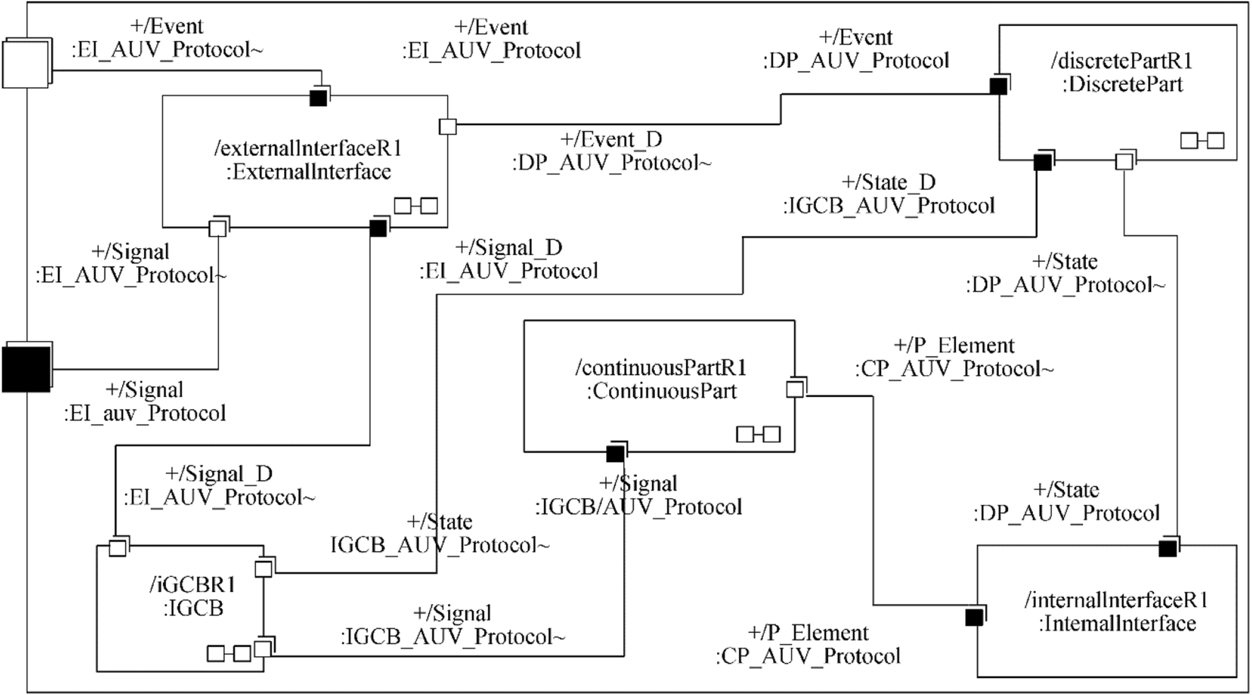 Figure 5 Capsule collaboration of real-time communication pattern for the AUV controller
The discrete part's capsule contains a set of situations Q and transitions A in the HA of the AUV controller (i.e., the macro-motion in horizontal transferring, idling, submerging/rising, and rotations [roll, pitch, and yaw], which are combined with the local state machine shown in Figure 3(b) in permutations.
The continuous part's capsule is combined with the continuous state space X in the implemented functional block diagram. The sequential evolution of continuous elements is carried out by specifying the rendezvous pattern introduced in the literature (Douglass 2011) with two sub-capsules called RendezVous and Semaphore.
The IGCB's capsule contains the concrete global continuous behaviors of the AUV being developed at a given time, similar to f ∈ F in its HA. f is derived from (1), (2), and the implemented functional block diagram (Figure 4). The concrete IGCB is also integrated into Algorithm 1 to estimate the position, depth, attitude, and velocity of the AUV. Each global continuous behavior corresponds to a situation in the HA.
The internal interface's capsule verifies Inv in the HA of the AUV being developed and generates internal events so that the discrete part's capsule can make its own evolution on the basis of these events.
The external interface's capsule is an intermediary that receives or sends episodic events and periodic signals between the developed AUV and the interacted systems, such as MES and MDS in the current model.
The timing concurrency of evolutions for the aforementioned capsule collaboration of the real-time communication pattern has been described in detail previously (Hien et al. 2018).
Reusability is important in implementing controllers for different AUV applications because it helps reduce the development time and cost. The various reusable views in the development phase are as follows. The reusable view is based on the virtual mechanism of objects, classes, or class hierarchies. The other reusable view can be based on design components and architecture, e.g., the implemented functional block diagram, the local state machine of the AUV controller, and the generic state machine of main control capsules that can be specified to develop various control applications of AUVs using the same technique. The specializations that permit the capsule collaboration of a developed AUV to be customizable and reusable in the new control application for various AUV types are summarized in Table 2.
Table 2 Main control capsules of PIM can be customized and reused in the new control application for various AUV typesMain control capsules Specialization description Generic artifacts Specialized artifacts Discrete capsule The discrete part's capsule remains at the generic level for the new AUV controller None Continuous part The ports and protocols of this capsule remain at the generic level for the new AUV controller The continuous part's capsule is specialized by adding or removing concrete continuous elements (xc∈X) that depend on the physical configuration of AUV actuators, e.g., the number of propeller motors related to the generated thrusts. The states and their behaviors, which correspond to the added/removed continuous elements, are added/removed in/from the state machine of this capsule. The behavior of the new set of continuous elements is used to redefine the concrete IGCBs (f∈F) IGCB The state machine, ports, and protocols of this capsule remain at the generic level for the new AUV controller The specification of the IGCB's capsule captures new IGCBs, which are formed by restructuring the new set of continuous elements according to the implemented functional block diagram. Jump, which denotes the initial value of each IGCB, must be identified Internal interface The state machine and ports of this capsule remain at the generic level for the new AUV controller The specialization of the internal interface's capsule is carried out by adding/removing in/from the new IGCB in the IGCB's capsule if necessary new Inv and Guard that correspond to new added/removed situations in/from the discrete part's capsule External interface The state machine, ports, and protocols of this capsule remain at the generic level for the new AUV controller The external interface's capsule is specialized by adding or removing input or output events from the outside (i.e., adding/removing these events in/from the protocol of this capsule) The interconnection of the main control capsules described in Figure remains at the generic level for various control applications of AUVs 3.3 Constructing the PSM for an AUV Controller
In the construction of the AUV controller, the PIM is first implemented in the PSM (i.e., the simulation model) that is transformed from the built PIM by using tools such as IBM Rational Rose RealTime or IBM Rational Software Architect RealTime (IBM 2018) and Modelica/OpenModelica (Fritzson 2015; OpenModelica 2018). IBM Rational's leading role in defining the real-time UML is widely acknowledged, as is the pre-eminence of the IBM Rational Rose RealTime or IBM Rational Software Architect RealTime products in implementing UML to support the architecting of large-scale, real-time, and embedded software systems. These tools combine a rich modeling environment with a code-oriented tool set to create a comprehensive practitioner desktop for creating solutions in a variety of architectural styles and targeted at specific runtime infrastructure. Many other important life cycle artifacts also benefit from this tool (e.g., requirement lists, test cases, and build scripts) to entirely cover development phases for the AUV controller. OpenModelica is an open source modeling and simulation environment intended for industrial and academic usage. It is an object-oriented declarative multi-domain modeling language for complex dynamic systems. The OpenModelica environment allows most of the expressions, algorithms, and function parts of Modelica to be executed interactively, as well as the equation models and Modelica functions to be compiled into efficient C/C++ codes. The generated C/C++ codes are combined with a library of utility functions, a runtime library, and a numerical differential algebraic equation solver. The obtained simulation results in OpenModelica allow us to theoretically evaluate control performance and functionalities and to easily optimize the control design elements before they are implemented and deployed. Then, the PIM with the optimized control elements of the simulation model is adapted to obtain the new updated PIM for the realization models of the AUV; the new PIM is called PIM*. This PIM* is converted into the new PSM* (i.e., the realization model) by using specific platforms based on an object-oriented implementation development environment (IDE), e.g., Arduino's IDE (Arduino 2018), to completely realize the AUV controller with compatible microcontrollers, e.g., ATMEGA32-U2 and STM32 Cortex-M4 microcontrollers (Arduino 2018). A sketch of the described model transformations is shown in Figure 6. Here, the transformations are performed through the round-trip engineering (i.e., forward and reverse engineering) of the intermediate C++ codes, including about 80% of the generated codes and 20% of the handcrafted codes, which are issued from the models depicted in IBM Rational Rose RealTime or IBM Rational Software Architect RealTime, OpenModelica tools, and Arduino's IDE.
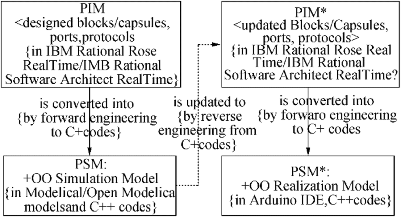 Figure 6 Sketch of PIM–PSM model transformation for AUV controllers
The transformation rules, which are used to convert the PIM into the PSM or the PIM* into the PSM*, and vice versa, through the round-trip engineering of the intermediate C++ codes are as follows:
• Each capsule is implemented by a class or block model.
• Each sub-capsule is carried out by a component class or block model and corresponds to the composite class or block model.
• Messages are implemented by the "functions" of classes or block models.
• Interfaces are realized by the set of inputs and outputs of a block model.
• Passive classes such as continuous elements or IGCBs are mapped to the "expressions" terms.
• The state machines of the main capsules are implemented by state graphs.
Figure 7(a)–(c) partially illustrate an example of the above transformation rules taken as excerpts between the designed PIM components of the IGCB capsule and the simulated PSM elements; the converted target is a Modelica/OpenModelica model. Here, we suppose that the PID regulator and motor actuator reside in the continuous part's capsule and that they are used to partially implement the functional block diagram for IGCB.
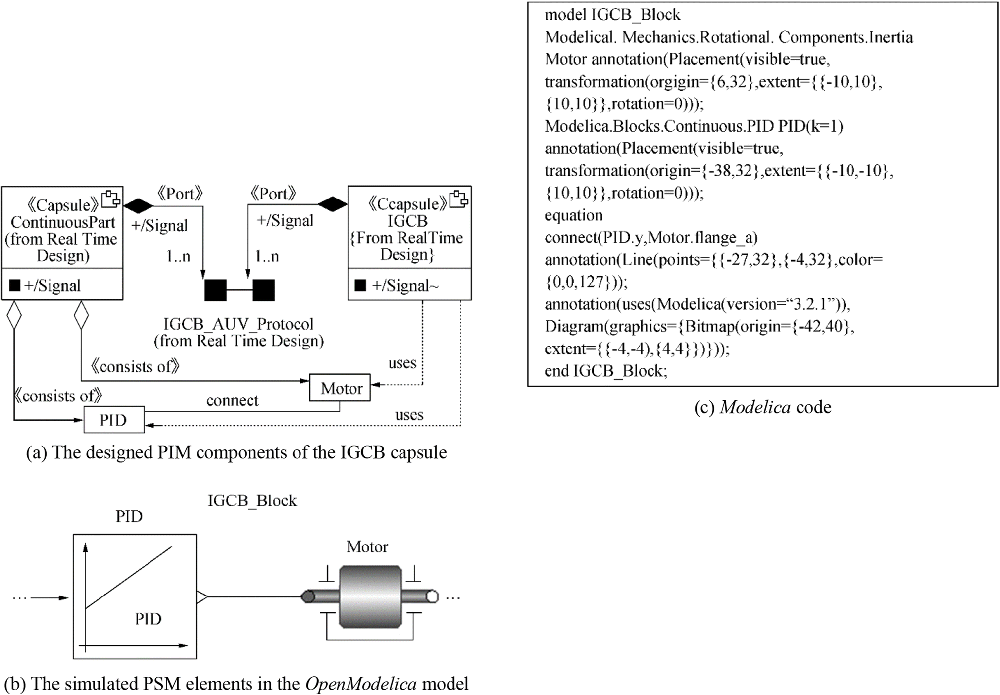 Figure 7 Illustration of transformation rules between parts of the designed PIM components and simulated PSM elements
The HA of an AUV controller can be automatically implemented in the object-oriented convention by using the state pattern described in the literature (Douglass 2011; Gamma et al. 1995). This pattern allows an object to alter its behavior when its internal state changes; the object appears to change its class. Following this pattern, an implementation structure of the HA (Figure 8) is specified to improve the evolution of the AUV controller. In this case, Arduino's platforms are used to realize the AUV controller. An example of the main generated codes of the HA's state pattern, which is verified and compiled to fit in the ATMEGA32-U2 and STM32 Cortex-M4 microcontrollers using Arduino IDE version 1.8.0 (Arduino 2018), is shown in the Appendix.
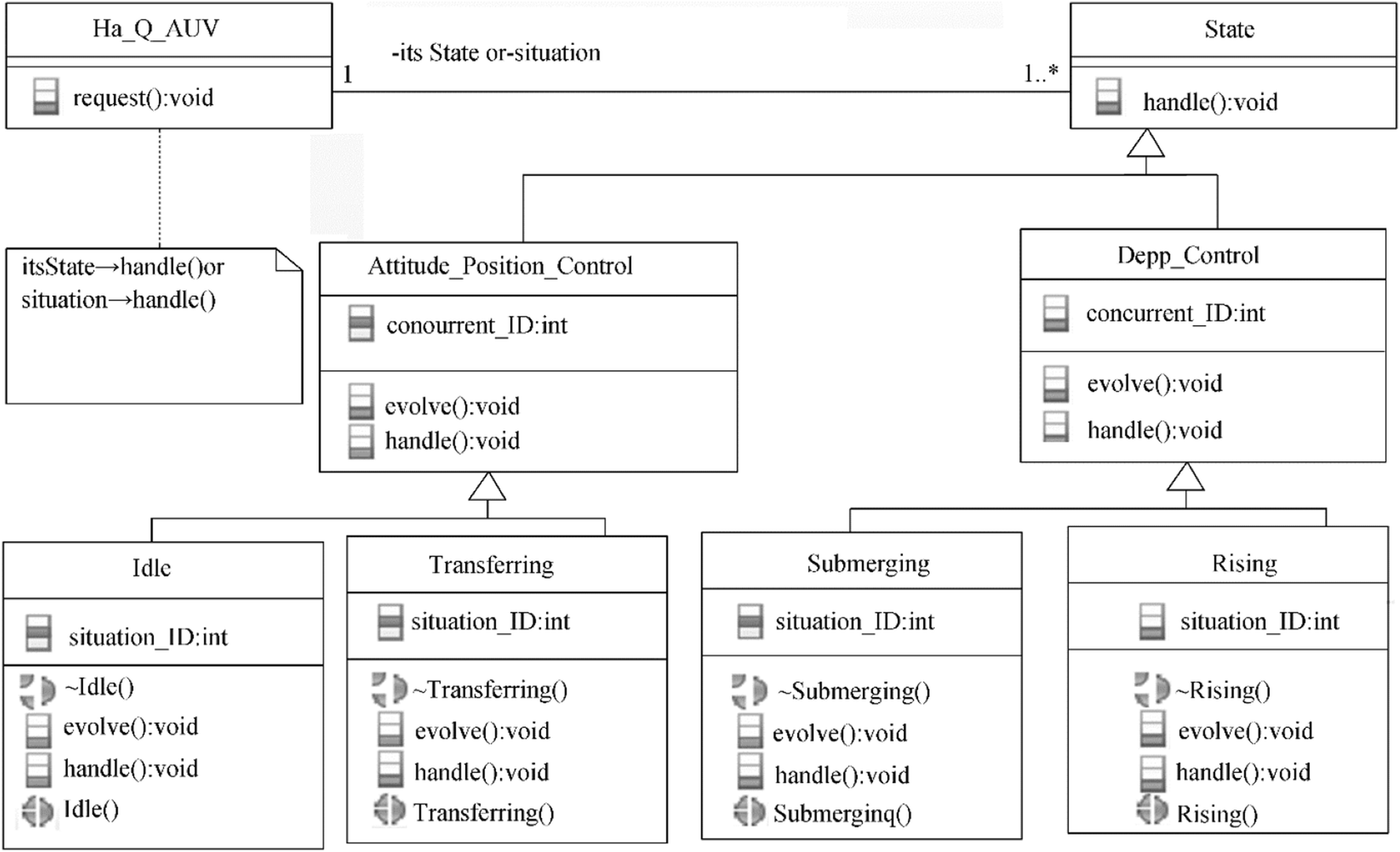 Figure 8 State pattern of HA for an AUV controller
4 Application
Following the above specialized model, we developed a planar trajectory-tracking controller that enables a miniature torpedo-shaped (M-AUV) with a small navigation bridge (Figure 9(a)–(e)) to reach and follow a desired planar trajectory. The main characteristics of the M-AUV are provided in Table 3.
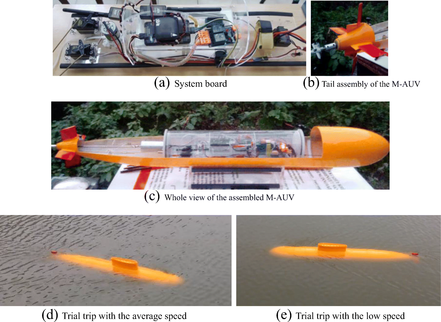 Figure 9 Installation and trial trips for the M-AUV controllerTable 3 Main characteristics of the M-AUV
Parameter Value Size (L × H × W) (m) 1.50 × 0.27 × 0.20 Net dry weight (kg) 12.30 Autonomy (min) 20 2 × Li-Po battery (V, mAh) 22.2, 20 000 Maximum load capacity (W) 314 Maximum immergence/emergence speed (m/s) 0.60 Maximum horizontal transferring speed (m/s) 2.0 Maximum diving depth (m) 1.20 Maximum radius of action (m) 400 In this application, the damping matrix is assumed as a diagonal matrix that allows the coupling between dissipative effects to be neglected because the velocities of the M-AUV are not too high; the mass matrix is considered a diagonal that is derived from the body reference frame aligned with the vehicle's principal axes of inertia.
We present an example of simulation cases in which the guidance and navigation system is assumed to address a drive event in the Transferring situation to the M-AUV controller with a desired course from the current position. One of the simulation results is then illustrated in Figure 10, which indicate the transient response of the M-AUV course. In this simulation scenario, we suppose that the M-AUV receives a desired course angle of 20° with a mean transferring velocity of 2.0 m/s. The transient duration is 4.8 s for the stabilized course. All the obtained simulation results allow us to theoretically evaluate the control performance of this application within the control criteria, such as the admissible timing response and transition and static errors. Subsequently, we can choose the designed control elements and their properties for implementing the realization model of this system.
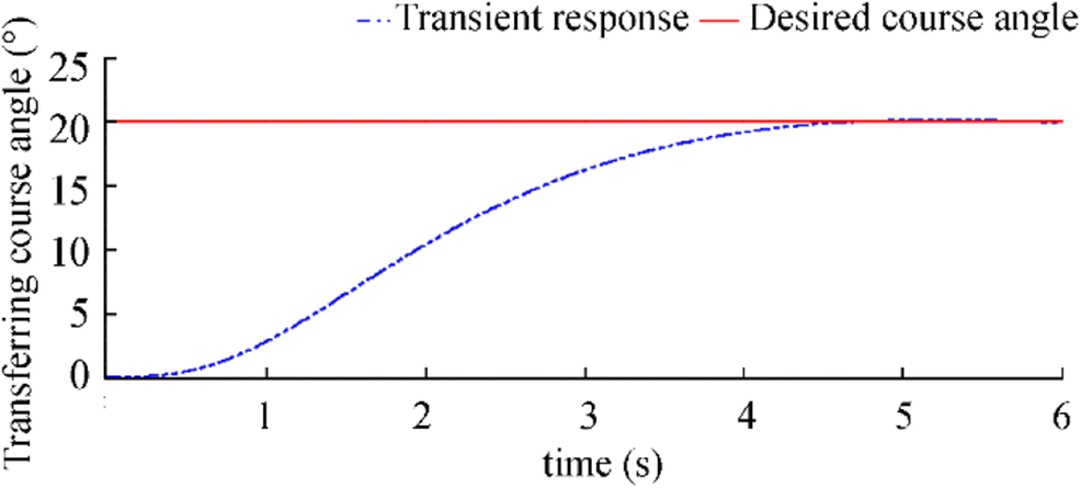 Figure 10 Transient response in a desired course from the current position
The Arduino platform (Arduino 2018) is also used to quickly deploy the realization model for the controller. This platform can sense the environment by receiving input from a variety of sensors, such as the pressure and magnetometer sensors, inertial measurement unit, and GPS, e.g., MPU6000 with a working frequency of 100 Hz (InvenSense 2018) and Ublox Neo 6 M with a working frequency of 10 Hz (u-blox 2018). It can affect its surroundings via the controlled actuators. The ATMEGA32-U2 and STM32 Cortex-M4 microcontrollers (Arduino 2018) are used on the board and can be programmed using Arduino's IDE based on C++. The main structure of the implemented code on the Arduino card is shown in Figure 11 by using the real-time UML component diagram.
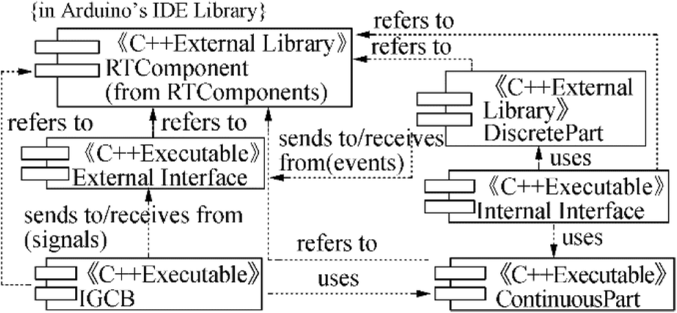 Figure 11 Main structure of the implemented code on Arduino card
The trial trip scenarios are based on the use case model, desired courses with different desired course angles, and various desired shape-based reference paths of the M-AUV and mean transferring speeds. The main test scenarios and their experimental data for this controller are performed in the laboratory. Some of the main course-tracking test results are shown in Table 4. Figure 12 illustrates the horizontal planar trajectory-tracking controller that enables the M-AUV to autonomously reach and follow the rectangle-shaped reference path. Figure 13 indicates the real horizontal planar positions of the M-AUV for a test scenario corresponding to the fourth test scenario described in Table 4.
Table 4 Test scenarios and experimental data in the stabilized courses of the M-AUVNo-o Desired course angle (degree) Mean transferring speed (m/s) Duration for the stabilized course (s) 1 010 1.0 5.2 2 010 2.0 4.5 3 020 1.0 5.5 4* 020 2.0 4.8 5 030 1.0 6.5 6 030 2.0 5.4 This test scenario corresponds to the simulation case shown in Figure 10 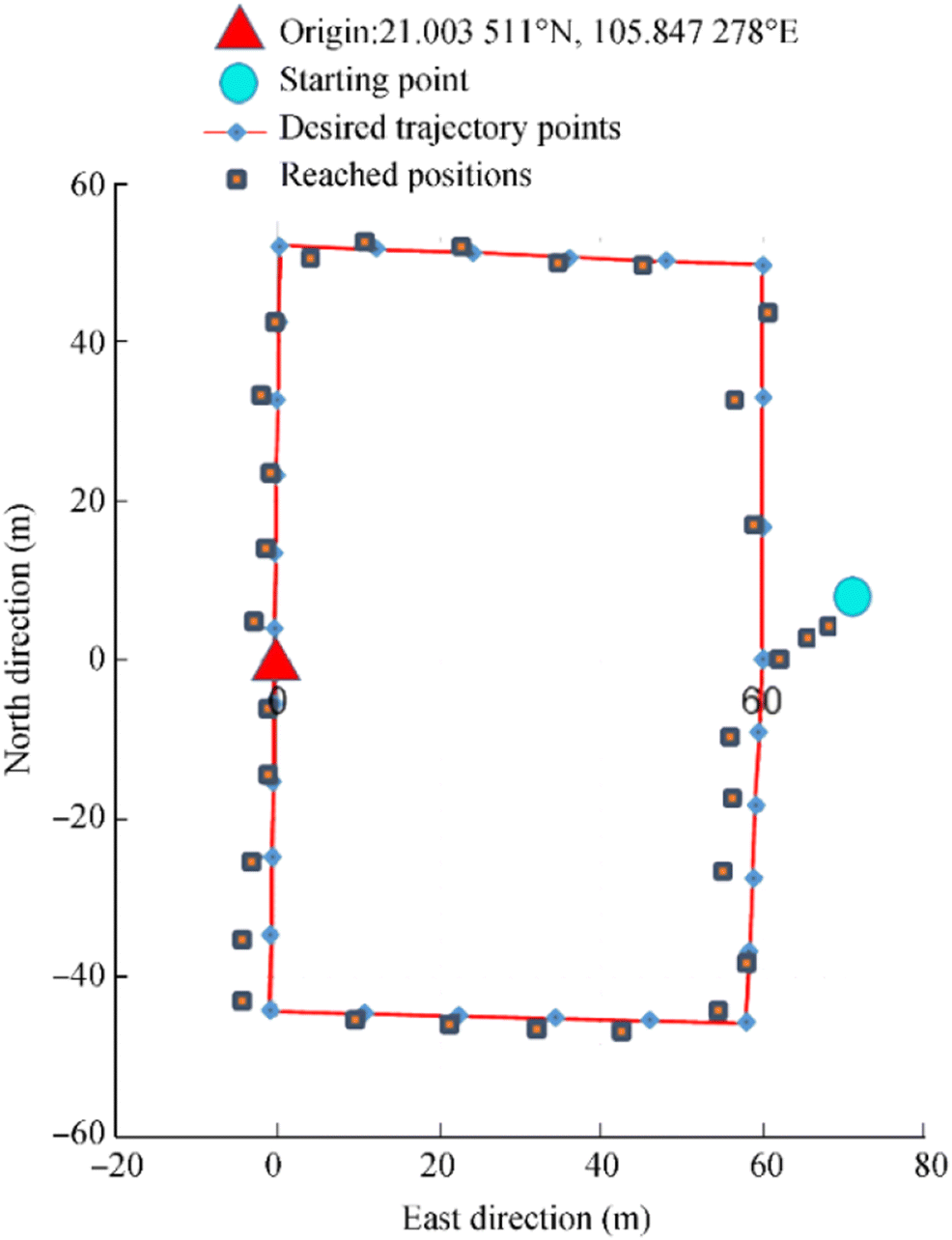 Figure 12 M-AUV reaches and follows the rectangle-shaped planar trajectory
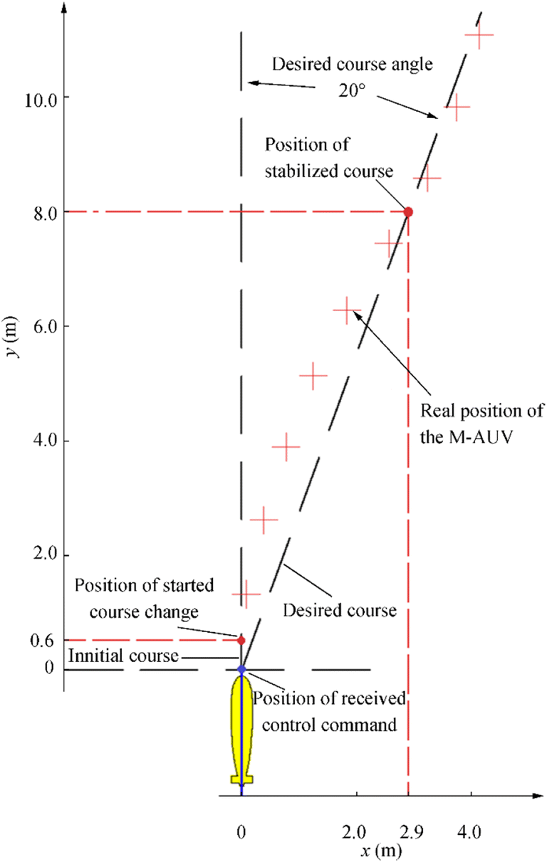 Figure 13 Real horizontal planar positions of the M-AUV corresponding to the fourth test scenario described in Table 4
Based on the comparison between the experimental data of these trial tests and the obtained experimental results from the literature (Hien et al. 2018), in which the IB control method and EKF algorithm were implemented, the planar trajectory-tracking controller of this M-AUV is improved in terms of the stabilized course duration and trajectory error, which decrease by about 2.0 s and 1.20 m, respectively. In this application, the standard control method of IB and the UKF algorithm are used for the position and attitude control. PID regulators are applied to the block of the motor controllers to implement the functional block diagram (Figure 4) for building up the ICCB's capsule of the PIM model.
5 Conclusion and Future Work
This paper presents a model-driven implementation to intensively realize controllers for AUVs whose global behaviors can be considered HDS. This model is mainly based on the specializations of MDA/MBSE's features combined with the real-time UML/SysML, UKF algorithm, and HA to closely analyze, design, implement, and realize the control parts of a system. No single formalism or language of an engineering process can possibly capture all the knowledge and information needed to solve complex control systems, such as AUV controllers. Hence, the dynamics and control structure of AUVs are adapted for the control and combined with the specialization of MDA/MBSE features, including the CIM, PIM, and PSM components. In the CIM, the use case model is specialized with continuous behaviors, the UKF algorithm, and HA to perform the requirement analysis for an AUV controller. The PIM is built to obtain the detailed design model by specifying the real-time control capsules, ports, and protocols enclosed with their intercommunication evolutions to model in detail the behaviors and structures of the AUV controller. The updated PIM with the optimized control elements of the simulation model (PIM*) is then converted into the PSM* through the round-trip engineering of the intermediate C++ codes so as to completely realize the AUV controller with compatible microcontrollers. Based on this model, a trajectory-tracking controller of a low-cost AUV is completely deployed and tested out with ATMEGA U2 and STM32-Cortex-M4 microcontrollers.
An assessment of the above application of the MDA/MBSE methodology can be summarized as follows:
Advantages
• It highlights a top global model that can combine the use case model with discrete models and continuous models (i.e., HA with the UKF algorithm) to estimate AUV states.
• The PIM-PSM separation and its model transformation allow the design model to distinguish which elements are customized and reused in the new control applications of AUVs.
• The user benefits from a chain of commercial or opensource software, such as the IBM Rational Rose RealTime or IBM Rational Software Architect RealTime, OpenModelica, and Arduino library. It could take advantage of the efforts of communities and facilitate the specialization of programming codes.
• The transformation rules can be rewritten to convert the real-time capsules of the PIM into PSM (Modelica/ OpenModelica) models of the PSM or PIM* into PSM* (Arduino IDE).
• Arduino microcontrollers are used widely in embedded system development, for which designers use opensource solutions.
• The Arduino platform can sense the environment by receiving inputs from a variety of sensors to allow for the extension of complex systems.
Disadvantages
• The product is naturally less specialized and could possibly lose speed performance. It may also require optimization.
• Development engineers may need to receive training in different IDEs to be able to manage the interfaces between tools.
• A version of real-time OpenModelica remains lacking; thus, quickly performing hardware-in-the-loop simulations may be difficult.
• Compiling and uploading the implemented programs in Arduino IDE could take time.
The developed control application shows that the MDA/MBSE approach combined with the real-time UML/SysML provides a framework and enables tools to be provided for specifying a system independent of the platform that supports it, specifying platforms, choosing a particular platform for the system, and transforming the specified system into one for a particular platform. However, the real-time UML/SysML versions lack constructs for modeling internal continuous behaviors for each state on the state machine diagram. An implemented functional block diagram must thus be defined in the CIM to model continuous behaviors for industrial HDS, such as an AUV controller with external events.
We have applied the above specialized model in a low-cost AUV controller, and we intend to implement it in new control applications for autonomous coordinated AUVs. In the near future, we will investigate the application strategy to extend its effectiveness and develop controllers for balancing search and target responses in cooperative teams of autonomous unmanned ships and various AUVs for ocean exploration.
Appendix
An example of the main "HA_Q_AUV.h" header and "HA_Q_AUV.h.cpp" implementation files of HA library for the developed AUV controller were implemented, verified, and compiled to fit in ATMEGA32-U2 and STM32 Cortex-M4 microcontrollers by using Arduino IDE version 1.8.0.

-
Figure 1 General control architecture for an AUV
Figure 2 Main use case model for the AUV controller
Figure 3 Dynamic behaviors of the "Track a desired trajectory" use case
Figure 4 Implemented functional block diagram for the AUV controller
Figure 5 Capsule collaboration of real-time communication pattern for the AUV controller
Figure 6 Sketch of PIM–PSM model transformation for AUV controllers
Figure 7 Illustration of transformation rules between parts of the designed PIM components and simulated PSM elements
Figure 8 State pattern of HA for an AUV controller
Figure 9 Installation and trial trips for the M-AUV controller
Figure 10 Transient response in a desired course from the current position
Figure 11 Main structure of the implemented code on Arduino card
Figure 12 M-AUV reaches and follows the rectangle-shaped planar trajectory
Figure 13 Real horizontal planar positions of the M-AUV corresponding to the fourth test scenario described in Table 4
Table 1 SNAME notations for underwater vehicles
Degree of freedom Motions Force and moment Linear and angular velocity Position and Euler angles 1 Surge X u x 2 Sway Y v y 3 Heave Z w z 4 Roll K p ϕ 5 Pitch M q θ 6 Yaw N r ψ Table 2 Main control capsules of PIM can be customized and reused in the new control application for various AUV types
Main control capsules Specialization description Generic artifacts Specialized artifacts Discrete capsule The discrete part's capsule remains at the generic level for the new AUV controller None Continuous part The ports and protocols of this capsule remain at the generic level for the new AUV controller The continuous part's capsule is specialized by adding or removing concrete continuous elements (xc∈X) that depend on the physical configuration of AUV actuators, e.g., the number of propeller motors related to the generated thrusts. The states and their behaviors, which correspond to the added/removed continuous elements, are added/removed in/from the state machine of this capsule. The behavior of the new set of continuous elements is used to redefine the concrete IGCBs (f∈F) IGCB The state machine, ports, and protocols of this capsule remain at the generic level for the new AUV controller The specification of the IGCB's capsule captures new IGCBs, which are formed by restructuring the new set of continuous elements according to the implemented functional block diagram. Jump, which denotes the initial value of each IGCB, must be identified Internal interface The state machine and ports of this capsule remain at the generic level for the new AUV controller The specialization of the internal interface's capsule is carried out by adding/removing in/from the new IGCB in the IGCB's capsule if necessary new Inv and Guard that correspond to new added/removed situations in/from the discrete part's capsule External interface The state machine, ports, and protocols of this capsule remain at the generic level for the new AUV controller The external interface's capsule is specialized by adding or removing input or output events from the outside (i.e., adding/removing these events in/from the protocol of this capsule) The interconnection of the main control capsules described in Figure remains at the generic level for various control applications of AUVs Table 3 Main characteristics of the M-AUV
Parameter Value Size (L × H × W) (m) 1.50 × 0.27 × 0.20 Net dry weight (kg) 12.30 Autonomy (min) 20 2 × Li-Po battery (V, mAh) 22.2, 20 000 Maximum load capacity (W) 314 Maximum immergence/emergence speed (m/s) 0.60 Maximum horizontal transferring speed (m/s) 2.0 Maximum diving depth (m) 1.20 Maximum radius of action (m) 400 Table 4 Test scenarios and experimental data in the stabilized courses of the M-AUV
No-o Desired course angle (degree) Mean transferring speed (m/s) Duration for the stabilized course (s) 1 010 1.0 5.2 2 010 2.0 4.5 3 020 1.0 5.5 4* 020 2.0 4.8 5 030 1.0 6.5 6 030 2.0 5.4 This test scenario corresponds to the simulation case shown in Figure 10 -
Allotta B, Caitib A, Costanzi R, Fanelli F, Fenucci D, Meli E, Ridolfi A (2016a) A new AUV navigation system exploiting unscented Kalman filter. Ocean Eng, Elsevier, ISSN 0029-8018 113: 121–132. https://doi.org/10.1016/j.oceaneng.2015.12.058 Allotta B, Conti R, Costanzi R, Fanelli F, Gelli J, Meli E, Monni N, Ridolfi A, Rindi A (2016b) A low cost autonomous underwater vehicle for patrolling and monitoring. J Eng Marit Environ, SAGE Publishing, ISSN 1475-0902 231: 740–749. https://doi.org/10.1177/1475090216681354 Antonelli G (2006) Underwater robots - motion and force control of vehicle-manipulator systems. Springer, Heidelberg Arduino (2018) Open-source electronics prototyping platform for hardware and software. Arduino. Available from http://www.arduino.cc/. Accessed on January 2018 Bar-Shalom Y, Li XR, Kirubarajan T (2001) Estimation with applications to tracking and navigation- theory algorithms and software. John Wiley & Sons, USA Bhopale P, Kazi F, Singh N (2019) Reinforcement learning based obstacle avoidance for autonomous underwater vehicle. J Mar Sci Appl, Springer, ISSN 1671-9433 18: 228–238. https://doi.org/10.1007/s11804-019-00089-3 Brignone L, Raugel E, Opderbecke J, Rigaud V, Piasco R, Ragot S (2015) First sea trials of HROV the new hybrid vehicle developed by IFREMER. In: OCEANS 2015 - Genova, Genova, Italy, IEEE, pp 1–7. https://doi.org/10.1109/OCEANS-Genova.2015.7271682 Carloni LP, Passerone R, Pinto A, Sangiovanni VA (2006) Languages and tools for hybrid systems design. Now Publishers Inc, Boston Cui W (2019) An overview of submersible research and development in China. J Mar Sci Appl, Springer, ISSN 1671-9433 17: 459–470. https://doi.org/10.1007/s11804-019-00121-6 Diem PG, Hien NV, Khanh NP (2013) An object-oriented analysis and design model to implement controllers for quadrotor UAVs by specializing MDA's features with hybrid automata and real-time UML. WSEAS Trans Syst, E-ISSN 2224-2678 12: 483–496 Douglass BP (2011) Design patterns for embedded Systems in C - an embedded software engineering toolkit, 1st edn. Elsevier, Oxford Douglass BP (2014) Real-time UML workshop for embedded systems, 2nd edn. Elsevier, Oxford Eslami M, Chin CS, Nobakhti AJ (2018) Robust modeling, sliding-mode controller, and simulation of an underactuated ROV under parametric uncertainties and disturbances. J Mar Sci Appl, Springer, ISSN 1671-9433. https://doi.org/10.1007/s11804-018-0037-1:1-15 Fishwick PA (ed) (2007) Handbook of dynamic system modeling. Taylor & Francis Group, USA Fossen TI (2002) Marine control systems: guidance, navigation and control of ships, rigs and underwater vehicles. Marine Cybernetics, Trondheim ISBN 82-92356-00-2 Fossen TI (2011) Handbook of marine craft hydrodynamics and motion control. John Wiley & Sons, United Kingdom Fritzson P (2015) Principles of object-oriented modeling and simulation with modelica 3.3: a cyber-physical approach, 2nd edn. Wiley-IEEE Press, USA Gamma E, Helm R, Johnson R, Vlissides J (1995) Design patterns: elements of reusable object-oriented software. Addison-Wesley, Oxford Henzinger TA, Kopke PW, Puri A, Varaiya P (1998) What's decidable about hybrid automata? J Comput Syst Sci, Elsevier, ISSN 0022-0000 57: 94–124. https://doi.org/10.1006/jcss.1998.1581 Hien NV, Soriano T (2012) A model transformation process to realize controllers of ship autopilot systems by the specialized MDA's features with UML/SysML. In: Proceedings of IEEE Conference on MECATRONICS-REM 2012, ISBN 978-1-4673-4771-6, Paris, France. IEEE, pp 20–26 Hien NV, Anh TV, Tuan KM et al. (2013) Research, design and manufacture control systems with the integration of object-oriented technology (MDA & Real-Time UML) and navigation units (INS/GPS) for autonomous underwater vehicles, final report of research project, funded by the state, code: KC03. TN05/11-15. Hanoi University of Science and Technology, Hanoi, Vietnam Hien NV, He NV, Diem PG (2018) A model-driven implementation to realize controllers for autonomous underwater vehicles. Appl Ocean Res, Elsevier, ISSN 0141-1187 78: 307–319. https://doi.org/10.1016/j.apor.2018.06.020 IBM (2018) IBM Rational's methodology, software, Online Documentation and Training Kits. IBM. Available from https://my15.digitalexperience.ibm.com/b73a5759-c6a6-4033-ab6b-d9d4f9a6d65b/dxsites/151914d1-03d2-48fe-97d9-d21166848e65/academic/home. Accessed on July 2018 INCOSE (2007) Systems Engineering Vision 2020, Version 2.03. INCOSE, San Diego, CA 92111-2222, USA INCOSE (2014) Systems Engineering Vision 2025. INCOSE, San Diego, CA 92111-2222, USA InvenSense (2018) Sensor System on Chip. Available from http://www.invensense.com/. Accessed on January 2018 Karkoub M, Wu HM, Hwang CL (2017) Nonlinear trajectory-tracking control of an autonomous underwater vehicle. Ocean Eng, Elsevier, ISSN 0029-8018 145: 188–198. https://doi.org/10.1016/j.oceaneng.2017.08.025 Lantos B, Márton L (2011) Nonlinear control of vehicles and robots. Springer, London Lekkas AM, Fossen TI (2014) Integral LOS path following for curved paths based on a monotone cubic hermite spline parametrization. IEEE Trans Control Syst Technol, ISSN 1063-6536 22: 2287–2301. https://doi.org/10.1109/TCST.2014.2306774 Li W, Wu W, Wang J, Wu M (2014) A novel backtracking navigation scheme for autonomous underwater vehicles. Measurement, Elsevier, ISSN 0263-2241 47: 496–504. https://doi.org/10.1016/j.measurement.2013.09.022 MahmoudZadeh S, Powers DMW, Yazdani AM, Sammut K, Atyabi A (2018) Efficient AUV path planning in time-variant underwater environment using differential evolution algorithm. J Mar Sci Appl, Springer, ISSN 1671-9433 17: 585–591. https://doi.org/10.1007/s11804-018-0034-4 MathWorks (2018) MATLAB and Simulink products. MathWorks. Available from https://www.mathworks.com/. Accessed on July 2018 OMG (2011) UML Profile for MARTE: Modeling and Analysis of Real-Time Embedded Systems Version 1.1 OMG (2014) Model Driven Architecture (MDA): Guide revision 2.0 of MDA Guide Version 1.0.1 (12th June 2003). OMG Document ormsc/2014-06-01 OMG (2015) Documents Associated With Unified Modeling Language™ (UML® Version 2.5). OMG OMG (2017) SysML Specifications Version 1.5. OMG OpenModelica (2018) OpenModelica. OpenModelica software, version 1.12. OpenModelica. Available from https://www.openmodelica.org/. Accessed on April 2018 Ribas D, Ridao P, Melchiorri C, Palli G, Fernández JJ, Sanz PJ (2015) I-AUV mechatronics integration for the TRIDENT FP7 project. IEEE/ASME Trans Mechatron, ISSN 1083-4435 20: 2583–2592. https://doi.org/10.1109/TMECH.2015.2395413 Sakairi T, Palachi E, Cohen C, Hatsutori Y, Shimizu J, Miyashita H (2013) Model based control system design using SysML, simulink, and computer algebra system. J Control Sci Eng, Hindawi, ISSN 1687-5249 2013: 14. https://doi.org/10.1155/2013/485380 Selic B, Gerard S (2014) Modeling and analysis of real-time and embedded systems with UML and MARTE. Elsevier, USA Shariati H, Moosavi H, Danesh M (2019) Application of particle filter combined with extended Kalman filter in model identification of an autonomous underwater vehicle based on experimental data. Ocean Eng, Elsevier, ISSN 0029-8018 82: 32–40. https://doi.org/10.1016/j.apor.2018.10.015 Shojaei K, Dolatshahi M (2017) Line-of-sight target tracking control of underactuated autonomous underwater vehicles. Ocean Eng, Elsevier, ISSN 0029-8018 133: 244–252. https://doi.org/10.1016/j.oceaneng.2017.02.007 SNAME (1950) Nomenclature for treating the motion of a submerged body through a fluid, technical and research bulletin No. 1-5. SNAME (the Society of Naval Architects and Marine Engineers), New York 18, N. Y., USA Soriano T, Hien NV, Tuan KM, Anh TV (2016) An object-unified approach to develop controllers for autonomous underwater vehicles. Mechatron Sci Intelligent Mach, Elsevier, ISSN 0957-4158 35: 54–70. https://doi.org/10.1016/j.mechatronics.2015.12.011 u-blox (2018) Gobal leader in wireless communications and positioning semiconductors and modules for the industrial, automotive and consumer markets. u-blox. Available from https://www.u-blox.com. Accessed on July 2018 Wan EA, Merwe RVD (2001) The unscented Kalman filter. In: Haykin S (ed) Kalman filtering and neural networks. Wiley, New York, pp 221–280 Wynn RB et al (2014) Autonomous underwater vehicles (AUVs): their past, present and future contributions to the advancement of marine geoscience. Mar Geol Int J Mar Geol Geochem Geophys, Elsevier, ISSN 0025-3227 352: 451–468. https://doi.org/10.1016/j.margeo.2014.03.012 Zheng Z, Zou Y (2016) Adaptive integral LOS path following for an unmanned airship with uncertainties based on robust RBFNN backstepping. ISA Trans, Elsevier, ISSN 0019-0578 65: 210–219. https://doi.org/10.1016/j.isatra.2016.09.008