Ultimate Compressive Strength Computational Modeling for Stiffened Plate Panels with Nonuniform Thickness
https://doi.org/10.1007/s11804-020-00180-0
-
Abstract
The aim of this paper is to develop computational models for the ultimate compressive strength analysis of stiffened plate panels with nonuniform thickness. Modeling welding-induced initial deformations and residual stresses was presented with the measured data. Three methods, i.e., ANSYS finite element method, ALPS/SPINE incremental Galerkin method, and ALPS/ULSAP analytical method, were employed together with existing test database obtained from a full-scale collapse testing of steel-stiffened plate structures. Sensitivity study was conducted with varying the difference in plate thickness to define a representative (equivalent) thickness for plate panels with nonuniform thickness. Guidelines are provided for structural modeling to compute the ultimate compressive strength of plate panels with variable thickness.Article Highlights• Validation of the computational models by a comparison with full-scale physical test.• Application of the three methods of ANSYS finite element method, ALPS/SPINE incremental Galerkin method, and ALPS/ULSAP analytical method.Open Access This article is licensed under a Creative Commons Attribution 4.0 International License, which permits use, sharing, adaptation, distribution and reproduction in any medium or format, as long as you give appropriate credit to the original author(s) and the source, provide a link to the Creative Commons licence, and indicate if changes were made. The images or other third party material in this article are included in the article's Creative Commons licence, unless indicated otherwise in a credit line to the material. If material is not included in the article's Creative Commons licence and your intended use is not permitted by statutory regulation or exceeds the permitted use, you will need to obtain permission directly from the copyright holder. To view a copy of this licence, visit http://creativecommons.org/licenses/by/4.0/.• Computational models for the ultimate compressive strength analysis of stiffened plate panels with nonuniform thickness.• Guidelines for structural modelling to compute the ultimate compressive strength of stiffened plate panels with nonuniform thickness -
1 Introduction
Plate panels are used in naval, offshore, mechanical, aerospace, and civil engineering structures as primary strength parts of ships, ship-shaped offshore installations, fuselages, box-girder cranes, and bridges. They are usually designed and built with a uniform thickness over the plating, but nonuniform thickness is sometimes allocated to fulfill practical design requirements (Zenkour 2003; Lee et al. 2019; Tash and Neya 2020).
During the past several decades, the emphasis on structural design has moved from the allowable stress design to the limit state design because the latter approach makes possible a rigorously designed, yet economical, structure that directly takes into consideration the various relevant modes of failure (Paik 2018). Furthermore, limit states are key criteria within the framework of quantitative risk assessment and management which is now recognized to be the best way to effectively manage extreme conditions and accidents associated with the volatile, uncertain, complex, and ambiguous environments at every stage of design, construction, operation, and decommissioining of structures and infrastructure, and ultimately resolve such challenges (Paik 2020).
A limit state is formally defined by the description of a condition for which a particular structural member of an entire structure would fail to perform the function designated beforehand, and four types of limit states are relevant for structures, namely the servicebility limit state (SLS), the ultimate limit state (ULS), the fatigue limit state (FLS), and the accidental limit state (ALS) from the viewpoint of structural design (Paik 2018). This paper deals with the ultimate limit state of a steel-stiffened plate structure under uniaxial compresive loads.
A number of useful studies on the ultimate strength of plate panels for marine applications are found in the literature (Abdussamie et al. 2018; Benson et al. 2011; Gannon et al. 2013, 2016; Iijima et al. 2015; Jagite et al. 2019, 2020; Khan and Zhang 2011; Khedmati et al. 2014, 2016; Kim et al. 2009, 2015; Kumar et al. 2009; Lee and Paik 2020; Magoga and Flockhart 2014; Ozguc et al. 2006; Paik 2007; Paik et al. 2013; Rahbar-Ranji and Zarookoan 2015; Ringsberg et al. 2018; Shi and Gao 2020; Shi and Wang 2012; Zhang 2016; Wang et al. 2009). For plate panels of engineering structures with variable or nonuniform thickness, the structural responses should be characterized by taking into account the effects of variable thickness. Zenkour (2003) and Tash and Neya (2020) studied the bending behavior of transversely isotropic thick rectangular plates with variable thickness. de Faria and de Almeida (2003) and Le-Manh et al. (2017) studied buckling of composite plates with variable thickness. Zhang et al. (2018) studied buckling of egg-shaped shells with variable thickness under external pressure loads. However, no studies on the ultimate strength of isotropic plate panels with variable or nonuniform thickness are found in the literature.
The aim of the present paper is to contribute to developing computational models for the ultimate compressive strength analysis of steel-stiffened plate panels with nonuniform thickness. The paper is a sequel to the articles of Paik et al. (2020a, b, c, d, e) that dealt with full-scale progressive collapse testing on steel-stiffened plate structures under various circumstances such as low temperature or fires.
2 A Target Stiffened Plate Panel
A stiffened plate panel subjected to axial compressive loads is considered as shown in Figure 1. The panel is composed of three bays. The plating of outer two bays has a same thickness of t. However, the thickness for a half of the plating in the central bay is t1 and t2. The target plate panel with t = t1 = t2 was fabricated with the framework of full-scale collapse tests (Paik 2020a, b, c, d and e), where the bottom plate panels of a containership carrying 1900 TEU were a reference.
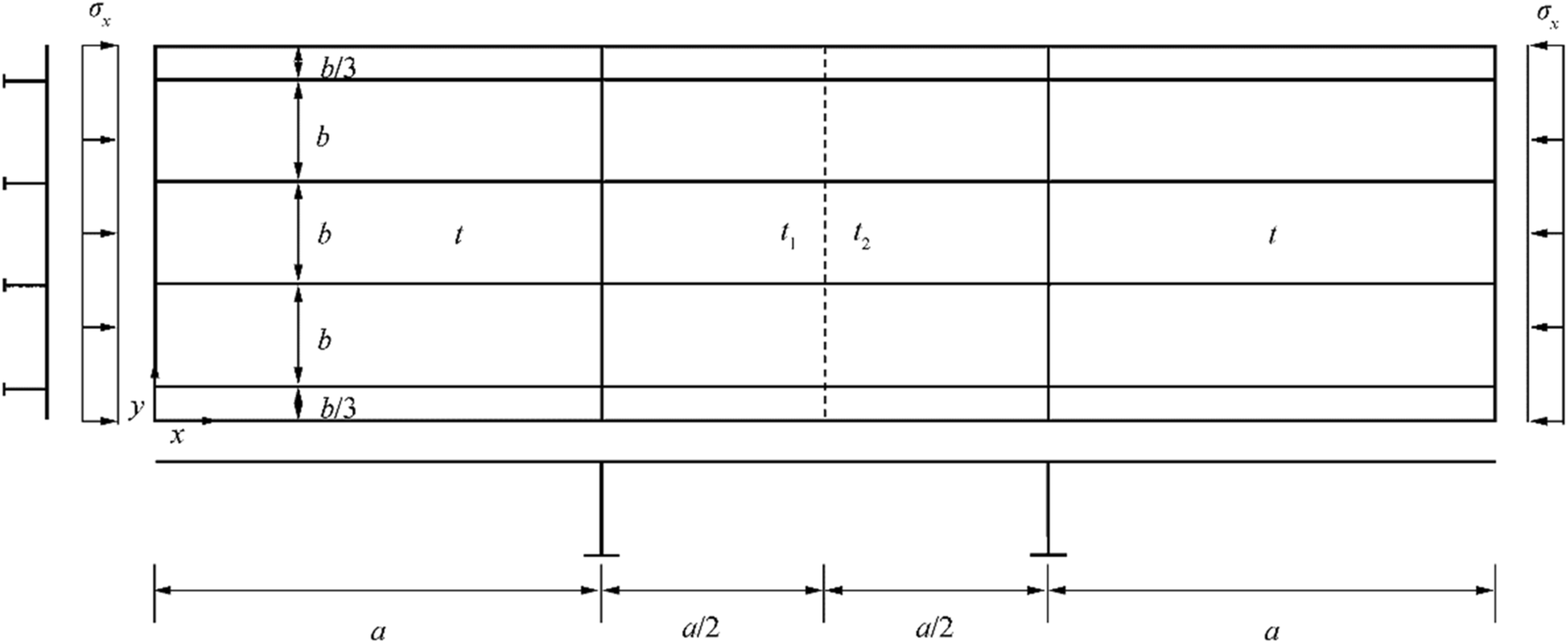 Figure 1 A stiffened plate panel
The panel has four longitudinal stiffeners and two transverse frames with T-type as shown in Figure 2. The dimensions of longitudinal stiffeners in outer two bays are the same, but they are larger than from those in the central bay. This means that the outer two bays may not buckle until the central bay reaches the ultimate limit state. Table 1 presents the dimensions of the plate panel. The plate panel is fixed along the loaded edges (i.e., left and right ends), but the unloaded edges are simply supported, i.e., with the constraints of lateral deformation but free rotation. Also, the unloaded edges are allowed to move in-plane freely, implying that they may not keep straight as the plate panel deflects due to buckling.
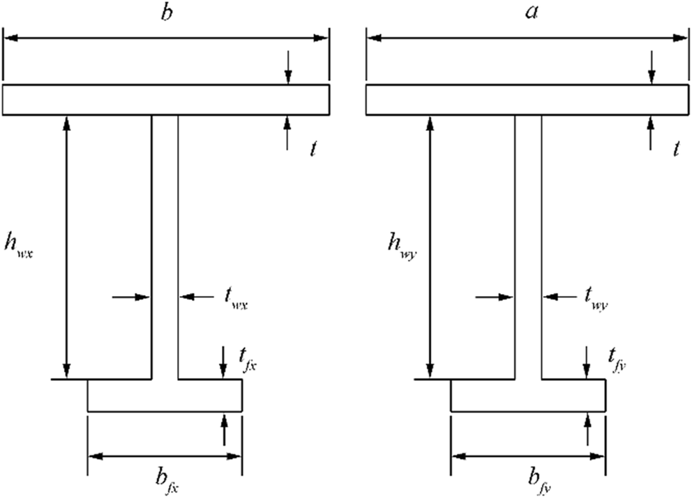 Figure 2 T-type support members in the x and y directionsTable 1 Dimensions of the target plate panel (unit: mm)
A b Plate thickness Longitudinal stiffener Transverse frame t t1 t2 Outer bays Central bay hwy twy bfy tfy 3150 720 10 Vary Vary hwx twx bfx tfx hwx twx bfx tfx 665 10 150 10 290 20 90 10 290 10 90 10 The plate panel is made of high tensile steel with grade AH32. To define the mechanical properties of the material, the tensile coupon tests were conducted with specimens made in compliance with ASTM E8 (ASTM 2011), as shown in Figure 3. Figure 4 shows one of typical engineering stress-engineering strain curves of the material obtained from tensile coupon tests with multiple specimens. Table 2 provides the mechanical properties of the AH32 steel.
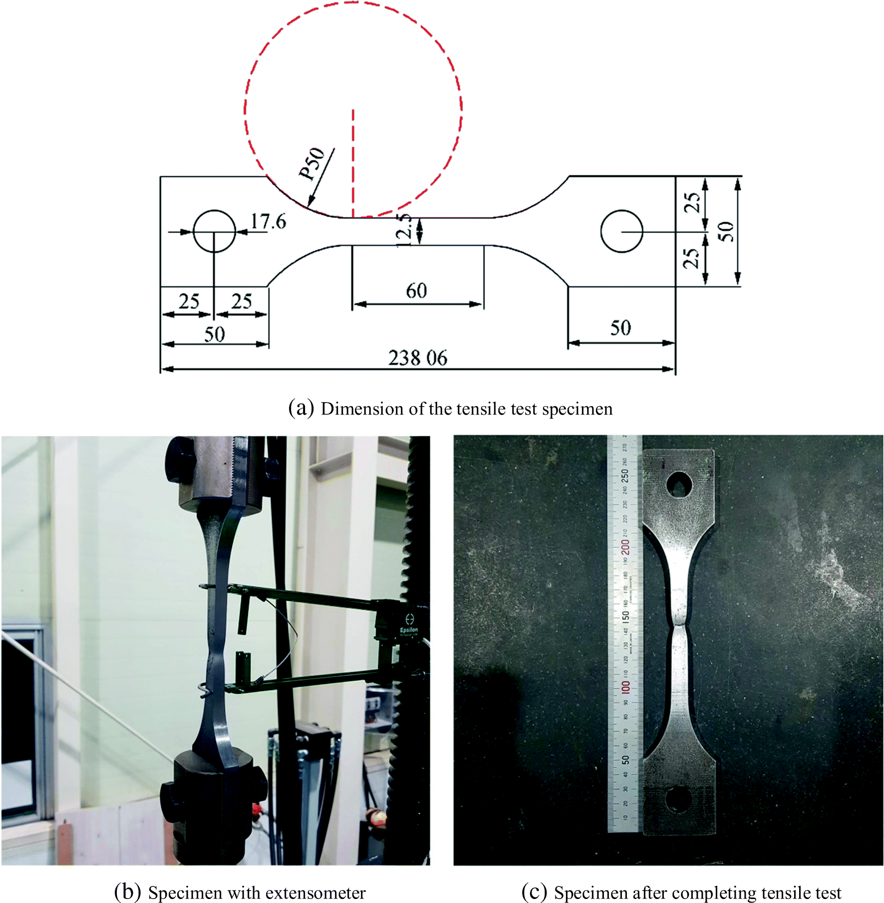 Figure 3 Specimen of material used for the structure before and after tensile coupon tests
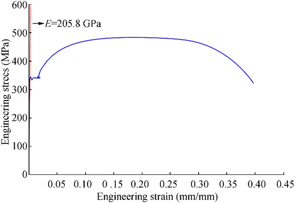 Figure 4 Engineering stress versus engineering strain curve of the AH32 steelTable 2 Mechanical properties of the AH32 steel obtained from the tensile coupon tests
Grade E (GPa) σY (MPa) σT (MPa) ν εf (%) AH32 205.8 331 483 0.3 40.0 E is the elastic modulus, σY is the yield strength, σT is the ultimate tensile strength, ν is the assumed Poisson's ratio, and εf is the fracture strain 3 Modeling of Weld Fabrication-Induced Initial Imperfections of the Plate Panel
The plate panel with t = t1 = t2 = 10 mm was fabricated in a shipyard in Busan, South Korea, which builds small and medium-sized merchant and patrol ships. The technology of welding was exactly the same as used for fabrication of real ship structures. The flux-cored arc welding (FCAW) technique was applied in accordance with the welding procedure specification (WPS) requirements as indicated in Table 3. As per the welding requirements of DNVGL (2017), the penetration of welding was fully achieved with a leg length of 7 mm as shown in Figure 5. Figure 6 shows the plate panel after fabrication was completed in the shipyard.
Table 3 Welding parameters of the actual welding process and welding procedure specificationsLeg length, Lw (mm) Welding parameter Weld condition Current (A) Voltage (V) Speed (cm/min) Heat input (kJ/cm) 7 WPS 225-275 23-32 24-34 7-18 Real condition 260 28 30 14.56 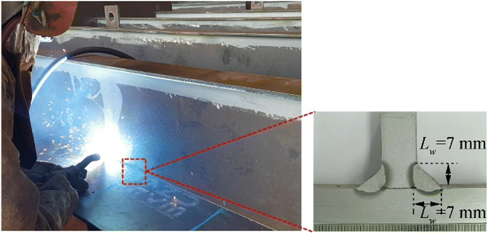 Figure 5 Full penetration of welds with a leg length of 7 mm
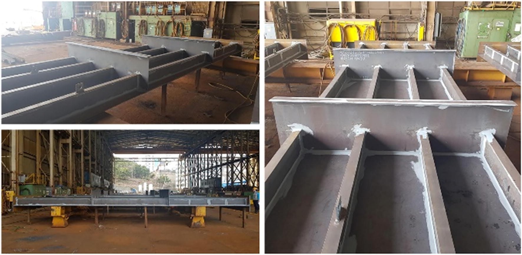 Figure 6 The plate panel after completing of fabrication in the shipyard
3.1 Modeling of the Plate Initial Deflection
A 3D scanner was used to measure the welding-induced initial deformations for plating and support members. For details of the initial deformation measurements together with the thermal-elastic-plastic large deformation finite element method computations, Yi et al. (2020a) is referred to. Figure 7 presents the welding-induced initial deflection of plating in the plate length and breadth directions. It is seen that not only plating but also transverse frames were deflected by welding, where the relative maximum of the plate initial deflection was found to be 1.73 mm based on the measured data. On the other hand, the maximum sideways deformation of longitudinal stiffeners was 0.42 mm which is 0.000133a. The web initial deflections for both longitudinal stiffeners and transverse frames were negligibly small (Figure 8).
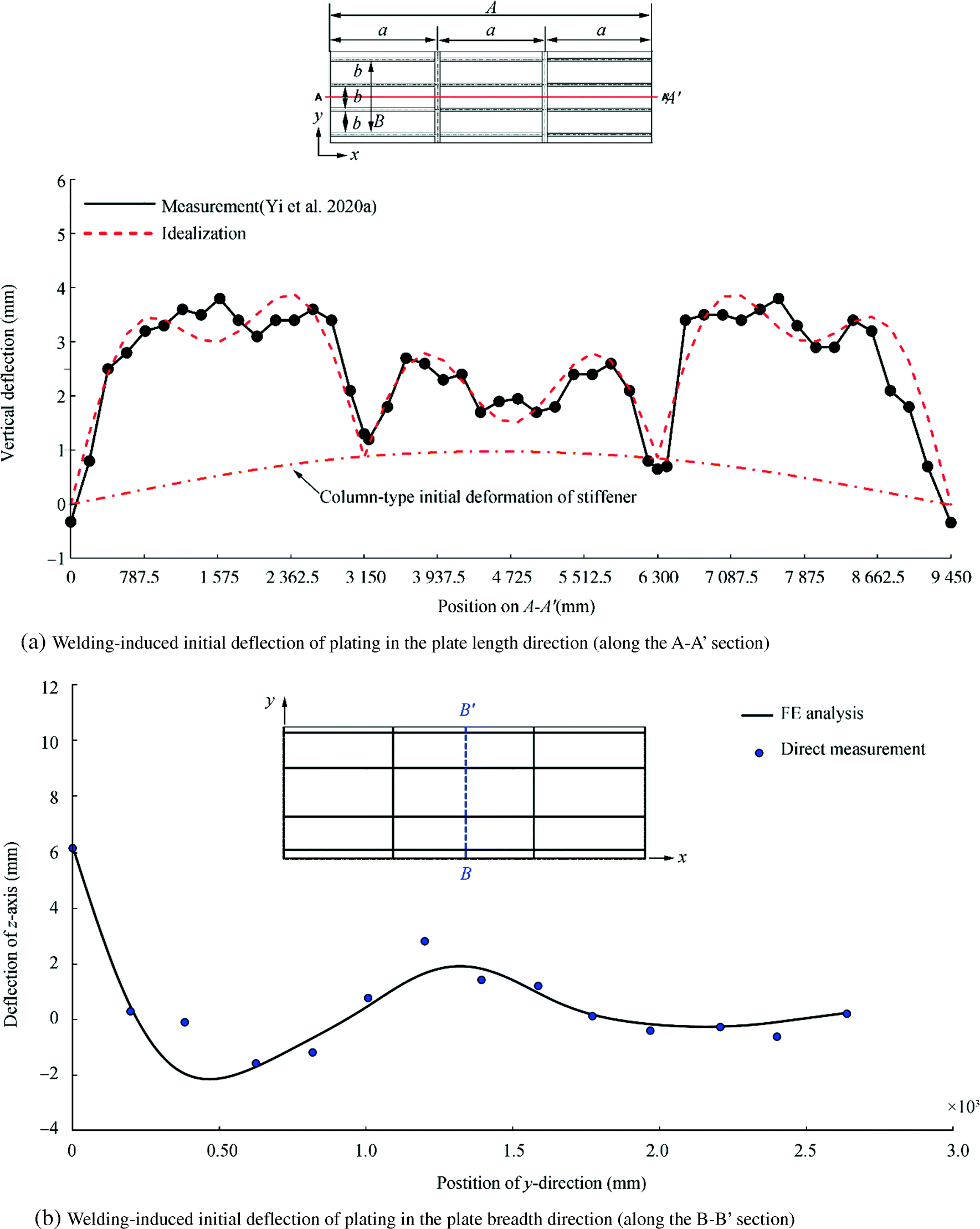 Figure 7 Comparison between direct measurements and numerical computations of plate initial deflections (Yi et al. 2020a)
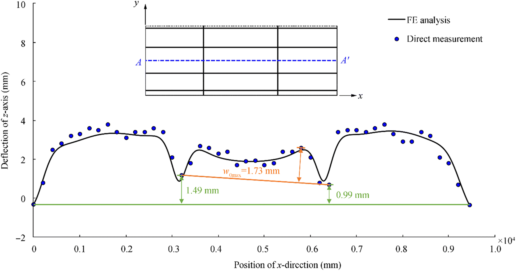 Figure 8 The maximum deflections of plating and transverse frames
The shape of the plate initial deflection is the so-called hungry horse's back type. In this case, the plate initial deflection of the central bay panel but excluding the unloaded side plates may be formulated by the following Fourier series equation (Paik 2018) where only a single half-wave between longitudinal stiffeners is allocated in the plate breadth direction.
$$ \frac{w_0}{w_{o\max }}=\sum \limits_{i=1}^{11}{B}_{oi3}\sin \frac{i\pi x}{a}\sin \frac{3\pi y}{B} $$ (1) where w0 is the plate initial deflection function, w0max is the maximum plate initial deflection, B = 3b is the breadth of the panel, and B0i3 is the coefficient of the plate initial deflection.
The buckling mode of plating is defined as an integer satisfying the following equation.
$$ \frac{a}{b}\le \sqrt{m\left(m+1\right)} $$ (2) where m is the buckling half-wave number. With a = 3150 mm and b = 720 mm, m = 4 is determined.
Equation (1) may be simplified with only the buckling component as follows:
$$ \frac{w_0}{w_{o\max }}={B}_{o43}\sin \frac{4\pi x}{a}\sin \frac{3\pi y}{B} $$ (3) where B043 is the buckling component of the plate initial deflection function which may be taken as B043 = 0.0259 (Paik 2018) as far as the hungry horse's back shape is applied.
3.2 Modeling of the Residual Stresses
As both longitudinal stiffeners and transverse frames are attached to the plating by welding, residual stresses must be developed in the two directions as shown in Figure 9. Tensile residual stresses are developed in the heat-affected zone, and compressive residual stresses are developed in the middle of plating to fulfill the equilibrium condition between internal forces. The X-ray diffraction (XRD) method was used to measure welding-induced residual stresses in the plate panel. Details of the residual stress measurements together with the thermal elastic-plastic finite element method computations and the simple formula estimations are presented in Yi et al. (2020b). Figure 10 shows the comparison of welding-induced residual stresses between direct measurement, finite element method computations, and simple formula estimations.
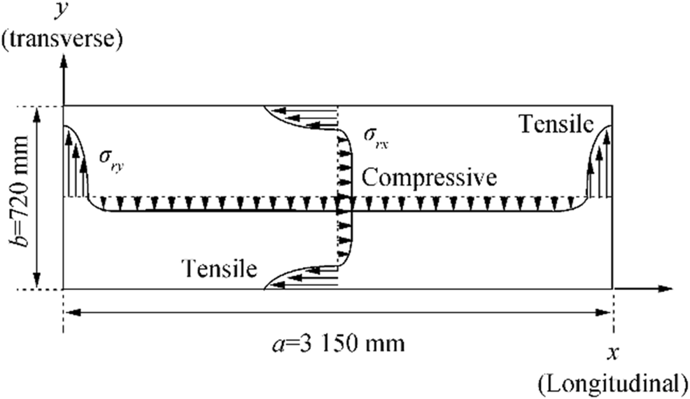 Figure 9 Distribution of welding-induced residual stresses in the two directions
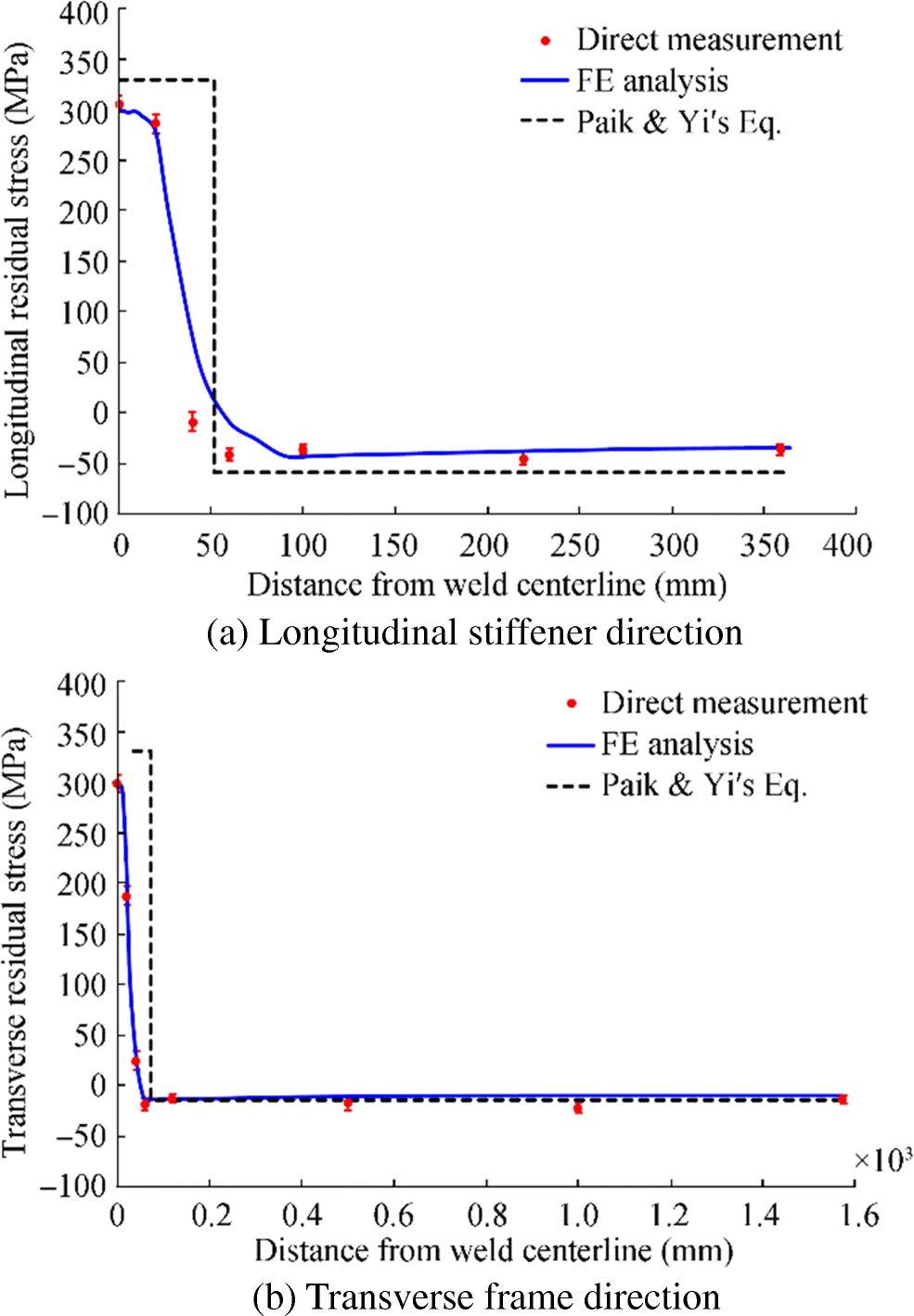 Figure 10 A comparison of welding-induced residual stresses between direct measurements, numerical predictions, and simple formula estimations
The distribution of welding-induced residual stresses is often modeled as rectangular blocks of tensile and compressive residual stresses as shown in Figure 11. For welded steel plates, the welding-induced residual stresses may be estimated by the following procedure (Paik 2018).
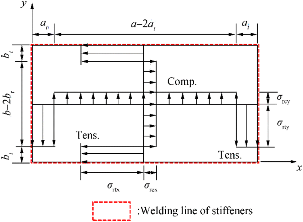 Figure 11 Idealization of the welding-induced residual stresses in a plate
From the equilibrium condition, the compressive residual stresses are obtained as follows:
$$ {\sigma}_{rcx}=\frac{2{b}_t}{2{b}_t-b}{\sigma}_{rtx} $$ (4a) $$ {\sigma}_{rcy}=\frac{2{a}_t}{2{a}_t-a}{\sigma}_{rty} $$ (4b) where bt and at are the breadth of tensile residual stress block in the plate breadth or length direction, respectively, σrtx, σrty are the magnitude of tensile residual stress block in the plate length or breadth direction, respectively, σrcx, σrcy are the magnitude of compressive residual stress block in the plate length or breadth direction, respectively, a is the plate length (spacing between transverse frames), and b is the plate breadth (spacing between longitudinal stiffeners). σrtx and σrty are approximately equal to σY (material yield strength) for structural steels.
Equation (4) indicates that the compressive residual stresses can be estimated once the breadths of tensile residual stress blocks are defined. Empirical formulations of bt and at were developed as a function of the weld leg length Lw as follows (Paik 2018):
$$ {b}_t={c}_1\times {L}_w+{c}_2 $$ (5) where $ {c}_1=-0.4562\times {\beta}_x^2+4.1994\times {\beta}_x+2.6354 $, $ {c}_2=1.1352\times {\beta}_x^2-4.3185\times {\beta}_x-11.1750 $ and $ {\beta}_x=\frac{b}{t}\sqrt{\frac{\sigma_Y}{E}} $.
$$ {a}_t={d}_1\times {L}_w+{d}_2 $$ (6) where $ {\displaystyle \begin{array}{c}{d}_1=-0.0399\kern.3em \times \kern.3em {\beta}_y^2\kern.3em +\kern.3em 2.0087\kern.3em \times \kern.3em {\beta}_y\kern.3em +8.7880\\ {}\end{array}} $, $ {d}_2=0.1042\times {\beta}_y^2-4.8575\times {\beta}_y-17.7950 $ and $ {\beta}_y=\frac{a}{t}\sqrt{\frac{\sigma_Y}{E}} $.
Using Eqs. (4)-(6), the magnitude of compressive residual stresses in the longitudinal and transverse directions can be estimated. The yield strength of the AH32 steel is 331 MPa, and thus, σY = σrtx = σrty = 331 MPa is taken. Also, the leg length for the applied weld condition is Lw = 7 mm. Therefore, the slenderness ratios are calculated as βx = 2.88 and βy = 12.63. Equations (5) and (6) provide the breadths of tensile residual stress blocks as follows:
$$ {\displaystyle \begin{array}{l}{c}_1=-0.4562\times {\beta}_x^2+4.1994\times {\beta}_x+2.6354\\ {}\kern0.75em =-0.4562\times {2.88}^2+4.1994\times 2.88+2.6354=10.9575\end{array}} $$ $$ {\displaystyle \begin{array}{l}{c}_2=1.1352\times {\beta}_x^2-4.3185\times {\beta}_x-11.1750\\ {}\kern0.75em =1.1352\times {2.88}^2-4.3185\times 2.88-11.1750=-14.1797\end{array}} $$ $$ {b}_t={c}_1\times {L}_w+{c}_2=51.5655\;\mathrm{mm} $$ $$ {\displaystyle \begin{array}{l}{d}_1=-0.0399\times {\beta}_y^2+2.0087\times {\beta}_y+8.7880\\ {}\kern0.75em =-0.0399\times {12.63}^2+2.0087\times 12.63+8.7880=27.7960\end{array}} $$ $$ {\displaystyle \begin{array}{l}{d}_2=0.1042\times {\beta}_y^2-4.8575\times {\beta}_y-17.7950\\ {}\kern0.75em =0.1042\times {12.63}^2-4.8575\times 12.63-17.7950=-95.7883\end{array}} $$ $$ {a}_t={d}_1\times {L}_w+{d}_2=70.9877\;\mathrm{mm} $$ The compressive residual stresses in the longitudinal and transverse directions are estimated from Eq. (4) as follows:
$$ {\sigma}_{rcx}=-55.34\ \mathrm{MPa},{\sigma}_{rcy}=-14.92\;\mathrm{MPa} $$ Figure 10 presents the validity of the procedure to estimate the welding-induced residual stresses in the plate panel.
4 Computational Models
4.1 ALPS/ULSAP (2020) Analytical Method
The primary modes of overall failure for a stiffened plate structure are categorized into the following six types (Paik 2018):
· Mode I: overall collapse of plating and stiffeners as a unit
· Mode II: plate collapse without distinct failure of stiffeners
· Mode III: beam column–type collapse
· Mode IV: collapse by local web buckling of stiffener
· Mode V: collapse by lateral-torsional buckling (tripping) of stiffener
· Mode VI: gross yielding
Some collapse modes may in some cases interact and occur simultaneously, but it is typically considered that the collapse of the stiffened panels occurs at the lowest value among the various ultimate loads calculated when considering each of the abovementioned six collapse patterns separately. Details of the ULS computations for each of the six collapse modes are found in Paik (2018), and they have been implemented into the ALPS/ULSAP program (2020). This method accommodates the application of combined load components such as biaxial compression/tension, biaxial in-plane bending, edge shear, and lateral pressure loads. The effects of welding-induced initial imperfections in the form of initial deformations and residual stresses are taken into account.
With ALPS/ULSAP, only the plate panel of the central bay which is assumed to be simply supported is taken as the extent of the analysis as shown in Figure 12. Also, only the buckling mode of the plate initial deflection is considered using Eq. (3). The measured values of the biaxial residual stresses are used but with the idealized distribution as shown in Figure 12. It is assumed that welding-induced residual stresses of longitudinal stiffeners are not considered. The column-type initial deflection of longitudinal stiffeners is assumed to be 0.0015a. The material follows the elastic-perfectly plastic model without considering strain-hardening effect.
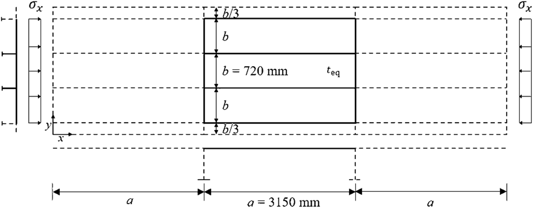 Figure 12 Extent of the ALPS/ULSAP and ALPS/SPINE analyses
A total of four cases with varying the thicknesses t1 and t2 are studied while the average value of them is kept constant at $ t=\frac{t_1+{t}_2}{2} $ as indicated in Table 4. For the ALPS/ULSAP analysis, the smaller value of the plate thickness, i.e., with teq = t2 when t1 ≥ t2 is used so that the ultimate strength is computed for the plate panel with a uniform thickness of teq = t2.
Table 4 Variation of the plate thickness (unit: mm)Case t t1 t2 teq = t2 1 10.0 10.0 10.0 10.0 2 10.0 10.5 9.5 9.5 3 10.0 11.0 9.0 9.0 4 10.0 11.5 8.5 8.5 4.2 ALPS/SPINE (2020) Incremental Galerkin Method
The incremental Galerkin method developed by Paik et al. (2001) and Paik and Lee (2005) is a semi-analytical method for computing the elastic-plastic large deflection behavior of steel or aluminum plates and stiffened panels up to their ultimate limit state (ULS). This method is designed to accommodate the geometric nonlinearity associated with buckling via an analytical procedure, whereas a numerical procedure accounts for the material nonlinearity associated with plasticity (Paik 2018). The method is unique in its use to analytically formulate the incremental forms of nonlinear governing differential equations for elastic large deflection plate theory. After solving these incremental governing differential equations using the Galerkin approach (Fletcher 1984), a set of easily solved linear first-order simultaneous equations for the unknowns is obtained, which facilitates a reduction in the computational effort.
It is normally difficult, but not impossible, to formulate the nonlinear governing differential equations to represent both geometric and material nonlinearities for plates and stiffened panels. A major source of difficulty is that an analytical treatment of plasticity with increases in the applied loads is quite cumbersome. An easier alternative is to deal with the progress of the plasticity numerically. The benefits of this method are to provide excellent solution accuracy with great savings in computational effort and to handle in the analysis the combined loading for all potential load components, including biaxial compression or tension, biaxial in-plane bending, edge shear, and lateral pressure loads. The effects of initial imperfections in the form of initial deflection and welding-induced residual stresses are also considered. The present theory can be applied to both steel and aluminum plate panels. Details of the IGM theory and applied examples described in Paik (2018) have been implemented into the ALPS/SPINE program.
In the following, some of the more important basic hypotheses used to formulate the incremental Galerkin method for computation of the elastic-plastic large deflection behavior of plate and stiffened panels are described (Paik 2018).
The plate panel is made of isotropic homogeneous steel or aluminum alloys with a Young's modulus of E and a Poisson's ratio of v. For a stiffened panel, Young's modulus of the plate part between stiffeners is the same as that of the stiffeners, but the yield stress of the plate part can differ from that of the stiffeners.
1) The length and breadth of the plate are a and b, respectively, as shown in Figure 13a. The plate thickness is t.
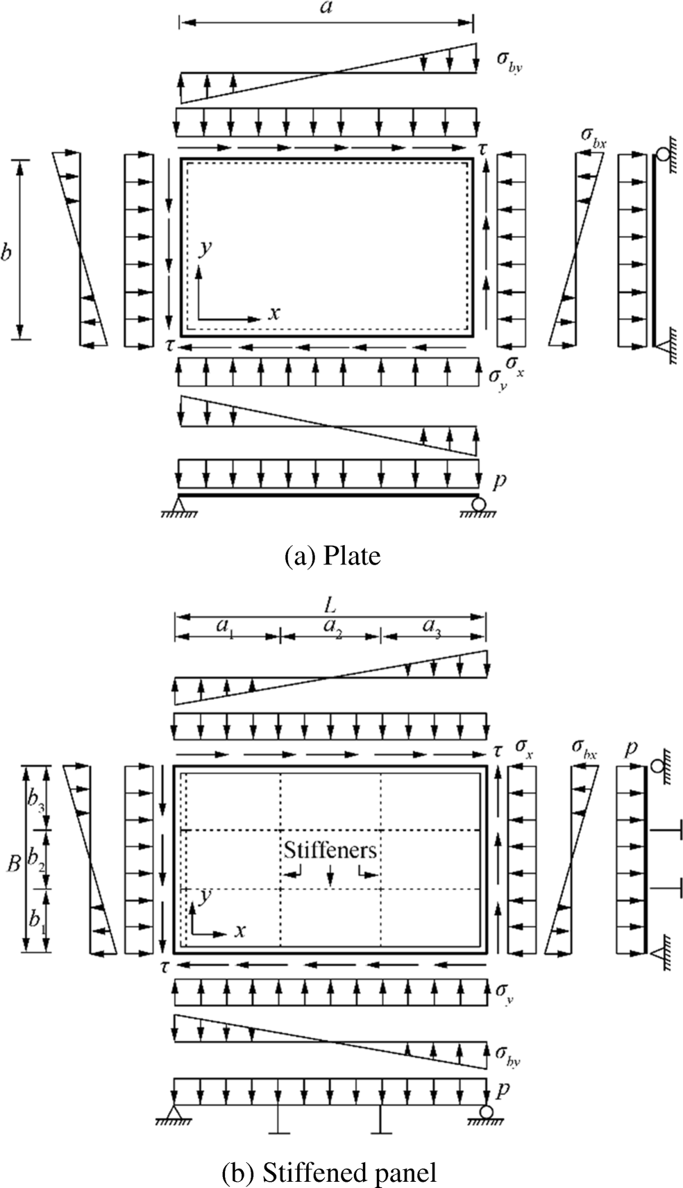 Figure 13 Application of combined in-plane and out-of-plane loads
2) The spacing of the stiffeners or the breadth of the plating between stiffeners can differ as shown in Figure 13b.
3) The material follows the elastic-perfectly plastic model without considering the strain-hardening effect.
4) The edge of the panel can be simply supported, clamped, or some combination of the two.
5) The panel is normally subjected to combined loads. Several potential load components act on the panel: biaxial compression or tension, edge shear, biaxial in-plane bending moment, and lateral pressure loads, as shown in Figure 14.
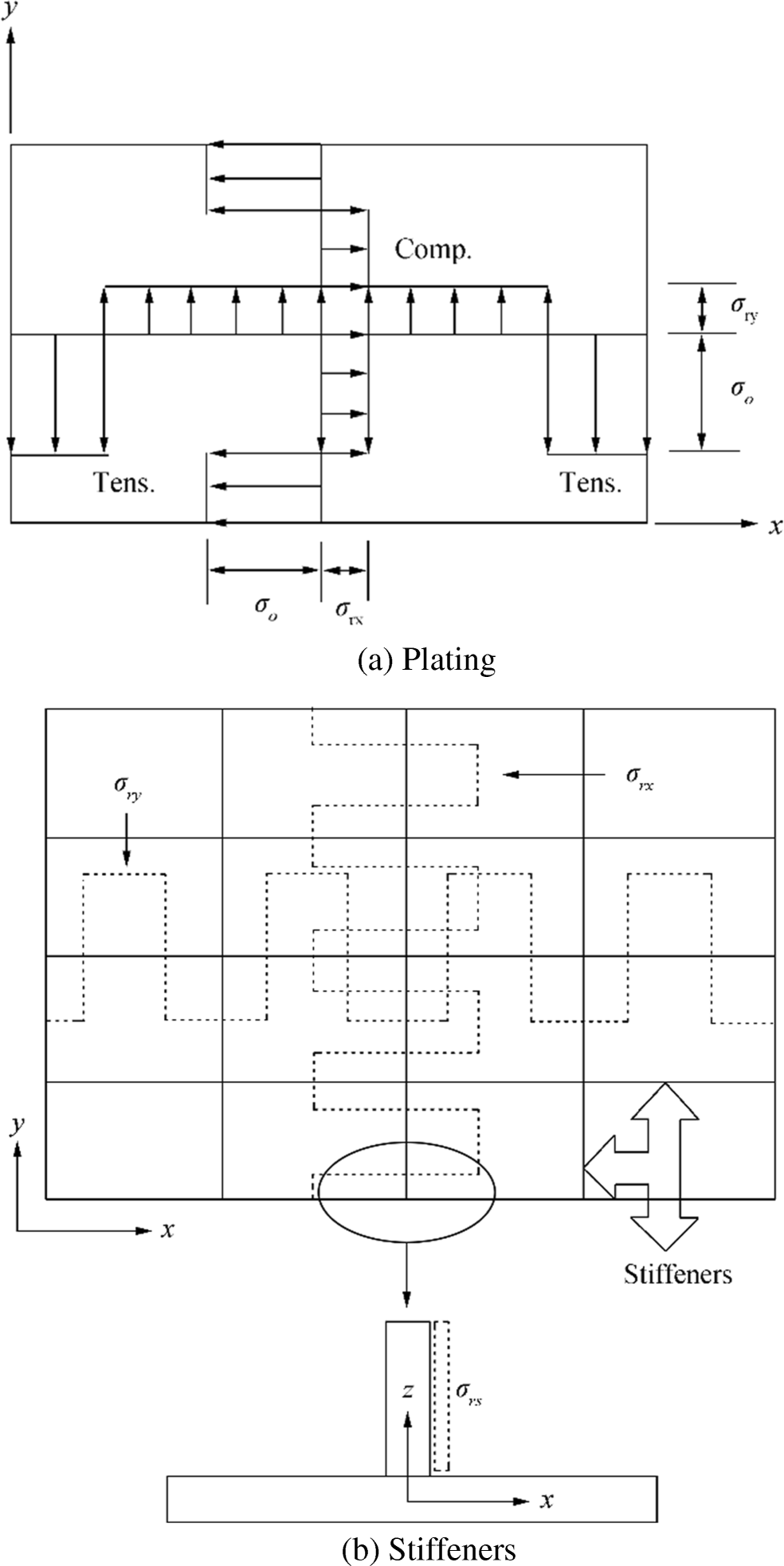 Figure 14 Idealized welding-induced residual stress distributions
6) The applied loads are increased incrementally.
7) The shape of the initial deflection in the plate panel is normally complex, but it can be expressed with a Fourier series function. For a stiffened panel, the plate part between stiffeners may have the same set of local plate initial deflections, whereas the stiffeners may have a different set of global column-type initial deflections.
8) Due to the welding along the panel edges and at the intersections between the lower part of the stiffener web and parent plate, the panel has welding-induced residual stresses. These can develop in the plate part in both x and y directions, as welding is normally carried out in these two directions. As shown in Figure 15, the distribution of welding-induced residual stresses for the plate part between stiffeners is idealized to be composed of two stress blocks, i.e., compressive and tensile residual stress blocks. It is assumed that the stiffener webs have uniform compressive residual stresses "equivalent" to that shown in Figure 14.
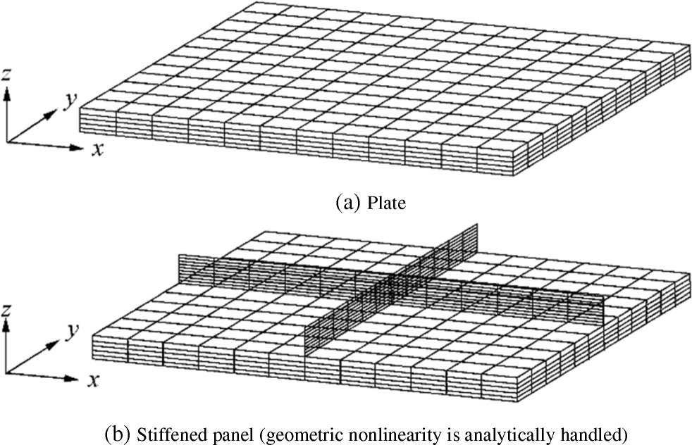 Figure 15 Example subdivision of mesh regions used for treatment of plasticity
9) For evaluation of the plasticity, it is assumed that the panel is composed of a number of membrane fibers in the x and y directions. Each membrane fiber is considered to have a number of layers in the z direction, as shown in Figure 15.
10) It is recognized that the strength of welded aluminum alloys in the softened zone may be recovered by natural aging over a period of time, but the ultimate strength of welded aluminum alloy panels may be reduced by softening phenomenon in the heat-affected zone as far as the material strength is not recovered. The effect of softening is accounted for using the technique noted in item 9 above.
The extent of the ALPS/SPINE analysis was the same as that of the ALPS/ULSAP analysis as shown in Figure 12. The plate initial deflection was assumed as follows:
$$ \frac{w_0}{w_{o\max }}=\sin \frac{\pi x}{a}\sin \frac{3\pi y}{B}+{B}_{o43}\sin \frac{4\pi x}{a}\sin \frac{3\pi y}{B} $$ (8) Furthermore, the added plate deflection under applied loads was assumed to follow the equation.
$$ w=\sum \limits_{i=1}^9{A}_{i3}\sin \frac{i\pi x}{a}\sin \frac{3\pi y}{B} $$ (9) where w is the added plate deflection and Ai3 is the amplitude of added deflection components.
Similar to the ALPS/ULSAP model, the measured values of the biaxial residual stresses were used but with the idealized distribution as shown in Figure 12. It was assumed that welding-induced residual stresses of longitudinal stiffeners were not considered. The column-type initial deflection of longitudinal stiffeners was assumed to be 0.0015a. Again, a total of four cases including one case with uniform plate thickness were studied as indicated Table 4. The smaller value of the plate thickness, i.e., with teq = t2 when t1 ≥ t2 was applied for the ALPS/SPINE analysis.
4.3 ANSYS (2019) Finite Element Method
The entire structure was taken as the extent of the analysis as shown in Figure 16. Only plate elements (with an aspect ratio of unity if possible) were used to model not only plating but also support members including both webs and flanges. The mesh size was taken as b / 10 for plating. Two elements (with one element at each side of T-bar) were used for the flange of longitudinal stiffener, and four elements (with two elements at each side of T-bar) were used for the flange of transverse frame.
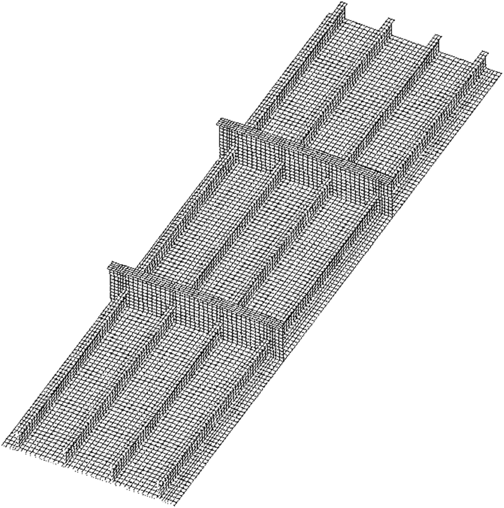 Figure 16 Extent of the ANSYS finite element method analysis
The plate initial deflection was assumed with only the buckling mode of Eq. (3). The measured initial deflection of transverse frames shown in Figure 8 was directly considered. The measured residual stresses were included in the modeling. The maximum sideway deformation of longitudinal stiffeners was applied, and the web initial deflections of both longitudinal stiffeners and transverse frames were neglected. In contrast to ALPS/ULSAP and ALPS/SPINE analyses, the actual plate thicknesses of t1 and t2 were directly included in the ANSYS modeling, while a total of four cases were studied as indicated in Table 4. The elastic-perfectly plastic material model was applied for the ANSYS analysis. Figure 17 shows the finite element model of the tested structure. Figure 18 shows the boundary condition applied for the ANSYS finite element analysis which was the same as for the tested structure.
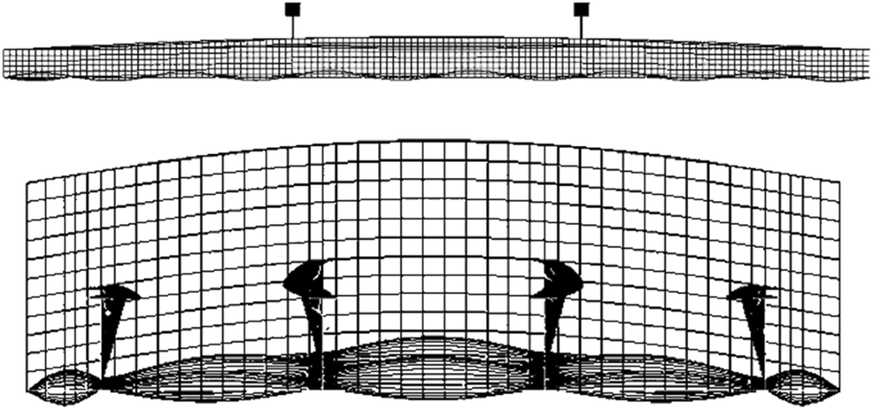 Figure 17 Modeling of initial deformations in the plate and support members
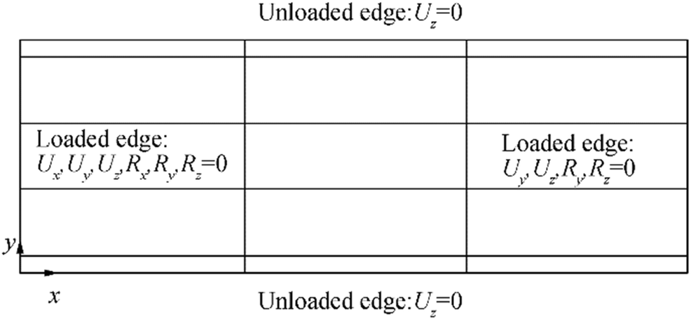 Figure 18 Boundary condition applied for the ANSYS finite element method analysis
5 Computed Results and Discussion
Figure 19 shows the applied compressive load versus axial shortening curves of the plate panel with t = t1 = t2 = 10 mm, where unloaded edges are allowed to move in-plane freely without keeping straight. To investigate the effect of the straight edge condition at unloaded edges, a comparison was made in terms of the in-plane displacement as shown in Figure 20. It is obvious from Figure 20 that the in-plane displacement was allowed for the nonstraight condition at unloaded edges, but the difference is very small and can be neglected. In fact, the computed results of the ANSYS finite element method in Figure 19 show identical despite the edge straight condition. Figure 21 shows the deformed shape of the plate panel with t = t1 = t2 = 10 mm at the ultimate limit state obtained from the ANSYS finite element method analysis. The deformed shape of the plate panel observed by the ANSYS analysis is comparable with that by the experiment as shown in Figure 22 where the panel reached the ultimate limit state by collapse mode V (tripping of the stiffeners), although the ANSYS computations did not show a clear tripping failure.
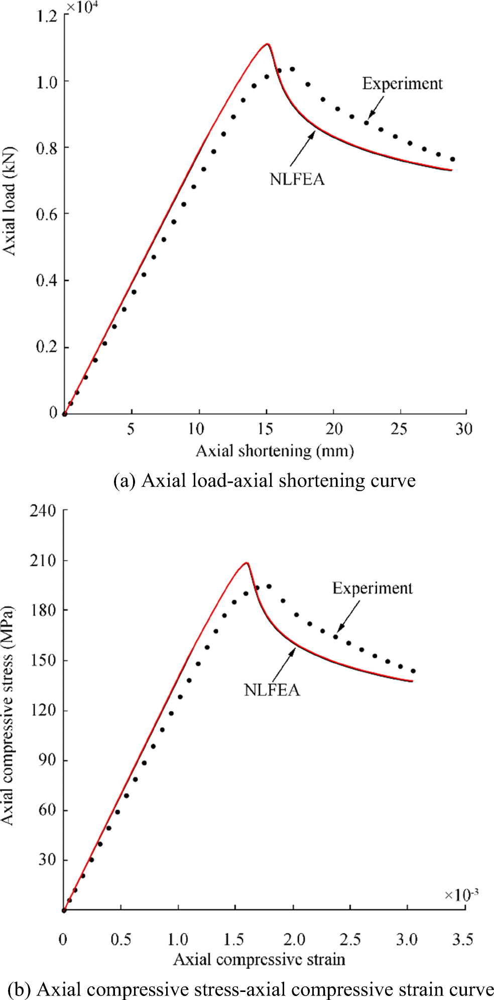 Figure 19 Comparison of the ultimate compressive strength behavior of the plate panel between the experiment and ANSYS finite element method analysis
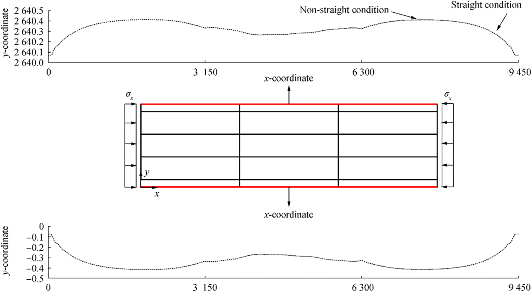 Figure 20 Effects of the straight condition at unloaded edges in terms of the in-plane displacement
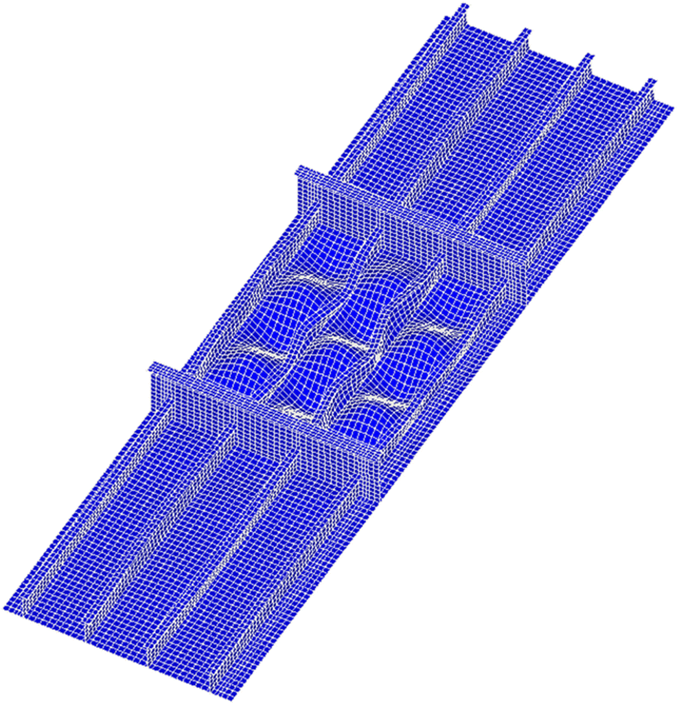 Figure 21 Deformed shape of the plate panel at the ultimate limit state obtained from the ANSYS finite element method analysis (with an amplification factor of 20)
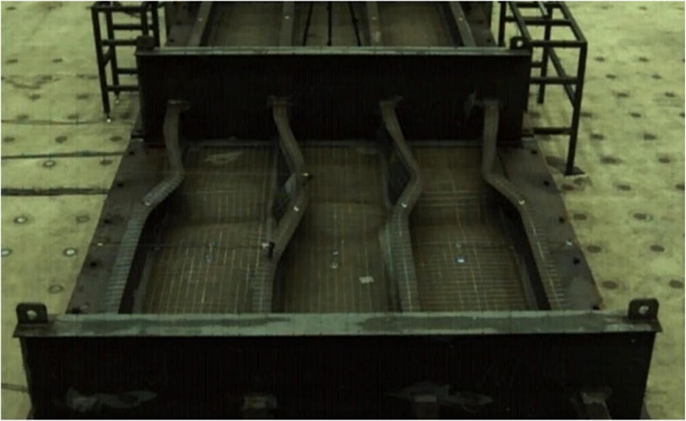 Figure 22 Deformed shape of the plate panel at the ultimate limit state observed from the experiment (Paik et al. 2020a)
To examine the effects of nonuniform thickness on the plate ultimate compressive strength, a series analyses were conducted with varying the plate thickness as indicated in Table 4, where the average value of the plate thickness is the same as 10 mm. Figure 23 shows the ultimate compressive strength behavior of the plate panel obtained from the ANSYS finite element method analysis with varying the plate thickness. Figure 24 shows the ALPS/SPINE analysis results in terms of added deflection components until the ultimate strength is reached with varying the plate thickness. It is interesting to see that the global pattern of the plate deflection increases in the beginning as the axial compressive loads are increased, but it eventually decreases (and disappears) as the plate buckles so that the buckling mode becomes dominant.
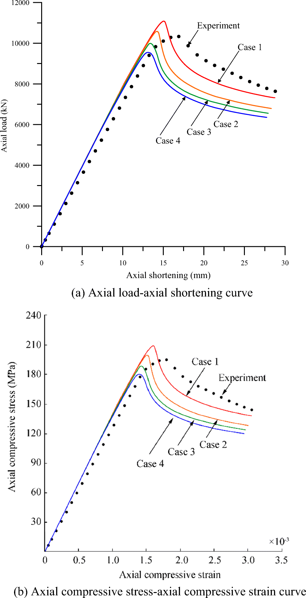 Figure 23 The ultimate compressive strength behavior of the plate panel obtained from the ANSYS finite element method analysis
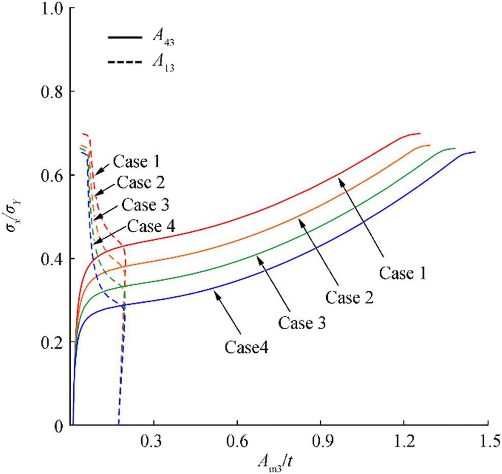 Figure 24 The ALPS/SPINE ultimate compressive strength behavior of the plate panel in terms of the added deflection components
The ALPS/ULSAP predictions were also carried out, and they showed that the panels of the four cases all reached the ultimate limit state by the tripping failure (collapse mode V). Table 5 summarizes the ultimate strength computations together with the experimental result. Figure 25 compares the ultimate compressive strengths obtained from the case studies. The ultimate strength obtained by ANSYS is greater than the experiment by 7.2% for case 1 with t = t1 = t2 = 10 mm. It is found that the ANSYS ultimate compressive strength computations of the plate panel with nonuniform thickness decrease as the lower plate thickness t2 decreases. For case 4 with a thickness difference of t1 − t2 = 3 mm, the reduction ratio of the ANSYS ultimate strength computation is 16.1%.
Table 5 Comparison of the ultimate compressive strength of the plate panels between the three method predictions together with the experiment (unit: MPa)Case Experiment ANSYS1 ALPS/ULSAP2 ALPS/SPINE2 1 248.6 266.5 240.6 232.1 2 - 254.4 237.5 222.7 3 - 240.2 234.8 220.2 4 - 229.5 232.7 217.4 1Actual t1 and t2 were applied
2teq = t2 (lower thickness) was applied Figure 25 Comparison of the ultimate compressive strength between the analyses and the experiment for the plate panel with varying the thickness
On the other hand, the analytical solutions for case 1 are smaller than the experiment by 3.2% for the ALPS/ULSAP analysis and 6.6% for the ALPS/SPINE analysis. By comparing with case 1 and case 4, the reduction rate of the ultimate strength is 3.3% for the ALPS/ULSAP analysis and 6.3% for the ALPS/SPINE analysis. It is obvious that the analytical solution of the panel ultimate strength decreases as the lower thickness decreases, but the reduction rate is much small in contrast to the ANSYS computations.
Based on the case studies, it is considered that the average thickness, i.e., $ {t}_{\mathrm{eq}}=\frac{t_1+{t}_2}{2} $ can approximately be used for the analytical approaches (e.g., ALPS/ULSAP or ALPS/SPINE) of plate panels with nonuniform thickness. The nonlinear finite element method can of course account for actual thicknesses directly.
6 Concluding Remarks
The aim of the paper was to investigate the effects of nonuniform thickness on the ultimate compressive strength of plate panels so that a recommended practice for defining a representative (equivalent) plate thickness was developed. Case studies were conducted by varying the plate thickness. Based on the studies, the following conclusions can be drawn.
1) The modeling techniques of welding-induced initial deflections and residual stresses in plate panels were presented in association with the measure data.
2) The ANSYS ultimate compressive strength computation for the plate panel with a uniform thickness of 10 mm (case 1) was greater than the experiment by 7.2%.
3) The ALPS/ULSAP or ALPS/SPINE ultimate compressive strength solutions for the plate panel of case 1 were smaller than the experiment by 3.2% and 6.6%, respectively.
4) According to the ANSYS computations, the ultimate compressive strength of plate panels with nonuniform thickness decreases as the lower thickness decreases or the thickness difference increases as far as the average thickness is kept constant.
5) The ALPS/ULSAP predictions showed that the plate panels of the four cases all reached the ultimate limit state triggered by tripping of the longitudinal stiffeners. This corresponds to the panel collapse mode of case 1 by the experiment.
6. The ALPS/ULSAP and ALPS/SPINE solutions show a similar trend to the ANSYS finite element method computations, but the reduction rate of the ultimate compressive strength is much smaller.
7. It is concluded that the average thickness for plate panels with nonuniform thickness can approximately be used as a representative for the ultimate compressive strength analysis by analytical methods which model the plate panels with uniform thickness.
-
Figure 1 A stiffened plate panel
Figure 2 T-type support members in the x and y directions
Figure 3 Specimen of material used for the structure before and after tensile coupon tests
Figure 4 Engineering stress versus engineering strain curve of the AH32 steel
Figure 5 Full penetration of welds with a leg length of 7 mm
Figure 6 The plate panel after completing of fabrication in the shipyard
Figure 7 Comparison between direct measurements and numerical computations of plate initial deflections (Yi et al. 2020a)
Figure 8 The maximum deflections of plating and transverse frames
Figure 9 Distribution of welding-induced residual stresses in the two directions
Figure 10 A comparison of welding-induced residual stresses between direct measurements, numerical predictions, and simple formula estimations
Figure 11 Idealization of the welding-induced residual stresses in a plate
Figure 12 Extent of the ALPS/ULSAP and ALPS/SPINE analyses
Figure 13 Application of combined in-plane and out-of-plane loads
Figure 14 Idealized welding-induced residual stress distributions
Figure 15 Example subdivision of mesh regions used for treatment of plasticity
Figure 16 Extent of the ANSYS finite element method analysis
Figure 17 Modeling of initial deformations in the plate and support members
Figure 18 Boundary condition applied for the ANSYS finite element method analysis
Figure 19 Comparison of the ultimate compressive strength behavior of the plate panel between the experiment and ANSYS finite element method analysis
Figure 20 Effects of the straight condition at unloaded edges in terms of the in-plane displacement
Figure 21 Deformed shape of the plate panel at the ultimate limit state obtained from the ANSYS finite element method analysis (with an amplification factor of 20)
Figure 22 Deformed shape of the plate panel at the ultimate limit state observed from the experiment (Paik et al. 2020a)
Figure 23 The ultimate compressive strength behavior of the plate panel obtained from the ANSYS finite element method analysis
Figure 24 The ALPS/SPINE ultimate compressive strength behavior of the plate panel in terms of the added deflection components
Figure 25 Comparison of the ultimate compressive strength between the analyses and the experiment for the plate panel with varying the thickness
Table 1 Dimensions of the target plate panel (unit: mm)
A b Plate thickness Longitudinal stiffener Transverse frame t t1 t2 Outer bays Central bay hwy twy bfy tfy 3150 720 10 Vary Vary hwx twx bfx tfx hwx twx bfx tfx 665 10 150 10 290 20 90 10 290 10 90 10 Table 2 Mechanical properties of the AH32 steel obtained from the tensile coupon tests
Grade E (GPa) σY (MPa) σT (MPa) ν εf (%) AH32 205.8 331 483 0.3 40.0 E is the elastic modulus, σY is the yield strength, σT is the ultimate tensile strength, ν is the assumed Poisson's ratio, and εf is the fracture strain Table 3 Welding parameters of the actual welding process and welding procedure specifications
Leg length, Lw (mm) Welding parameter Weld condition Current (A) Voltage (V) Speed (cm/min) Heat input (kJ/cm) 7 WPS 225-275 23-32 24-34 7-18 Real condition 260 28 30 14.56 Table 4 Variation of the plate thickness (unit: mm)
Case t t1 t2 teq = t2 1 10.0 10.0 10.0 10.0 2 10.0 10.5 9.5 9.5 3 10.0 11.0 9.0 9.0 4 10.0 11.5 8.5 8.5 Table 5 Comparison of the ultimate compressive strength of the plate panels between the three method predictions together with the experiment (unit: MPa)
Case Experiment ANSYS1 ALPS/ULSAP2 ALPS/SPINE2 1 248.6 266.5 240.6 232.1 2 - 254.4 237.5 222.7 3 - 240.2 234.8 220.2 4 - 229.5 232.7 217.4 1Actual t1 and t2 were applied
2teq = t2 (lower thickness) was applied -
Abdussamie N, Ojeda R, Daboos M (2018) ANFIS method for ultimate strength prediction of unstiffened plates with pitting corrosion. Ships and Offshore Structures 13(5): 540-550 https://doi.org/10.1080/17445302.2018.1439668 ALPS/SPINE (2020) Elastic-plastic large deflection analysis of plates and stiffened pan els under combined biaxial compression / tension, biaxial in-plane bending, edge shear and lateral pressure loads. MAESTRO Marine LLC, Greenboro https://www.maestromarine.com. Accessed on 3 Jan 2020 ALPS/ULSAP (2020) Ultimate strength analysis of plates and stiffened panels under combined biaxial compression / tension, edge shear and lateral loads. MAESTRO Marine LLC, Greenboro https://www.maestromarine.com Accessed on 3 Jan 2020 ANSYS (2019) User's manual (version 10.0). ANSYS Inc., Canonsburg ASTM (2011) ASTM E8/E8M-09 Standard test methods for tension testing of metallic materials. ASTM International, West Conshocken, PA Benson S, Downes J, Dow RS (2011) Ultimate strength characteristics of aluminium plates for high-speed vessels. Ships and Offshore Structures 6(1-2): 67-80 https://doi.org/10.1080/17445302.2010.529696 de Faria AR, de Almeida SFM (2003) Buckling optimization of plates with variable thickness subjected to nonuniform uncertain loads. Int J Solids Struct 40: 3955-3966 https://doi.org/10.1016/S0020-7683(03)00177-X DNVGL (2017) Rules for classification—ships, part 2 materials and welding, chapter 4 fabrication and testing. Høvik, Norway Fletcher CAJ (1984) Computational Galerkin method. Springer-Verlag, New York Gannon L, Liu Y, Pegg N, Smith MJ (2013) Effect of three-dimensional welding-induced residual stress and distortion fields on strength and behaviour of flat-bar stiffened panels. Ships and Offshore Structures 8(5): 565-578 https://doi.org/10.1080/17445302.2012.707386 Gannon L, Liu Y, Pegg N, Smith MJ (2016) Nonlinear collapse analysis of stiffened plates considering welding-induced residual stress and distorion. Ships and Offshore Structures 11(3): 228-244 https://doi.org/10.1080/17445302.2014.985428 Iijima K, Suzaki Y, Fujikubo M (2015) Scaled model tests for the post-ultimate strength collapse behaviour of a ship's hull girder under whipping loads. Ships Offshore Struct 10(1): 31-38 https://doi.org/10.1080/17445302.2013.870774 Jagite G, Bigot F, Derbanne Q, Malenica S, Le Sourne H, de Lauzon J, Cartraud P (2019) Numerical investigation on dynamic ultimate strength of stiffened panels considering real loading scenarios. Ships and Offshore Structures 14(suppl): 374-386 Jagite G, Bigot F, Derbanne Q, Malenica S, Le Sourne H, Cartraud P (2020) A parametric study on the dynamic ultimate strength of a stiffened panel subjected to wave- and whipping-induced stresses. Ships and Offshore Structures: 1-15. https://doi.org/10.1080/17445302.2020.1790985 Khan I, Zhang S (2011) Effects of welding-induced residual stress on ultimate strength of plates and stiffened panels. Ships and Offshore Structures 6(4): 297-309 https://doi.org/10.1080/17445301003776209 Khedmati MR, Pedram M, Rigo P (2014) The effects of geometrical imperfections on the ultimate strength of aluminium stiffened plates subject to combined uniaxial compression and lateral pressure. Ships and Offshore Structures 9(1): 88-109 https://doi.org/10.1080/17445302.2012.726761 Khedmati MR, Memarian HR, Fadavie M, Zareel MR (2016) Empirical formulations for estimation of ultimate strength of continuous aluminium stiffened plates under combined transverse compression and lateral pressure. Ships and Offshore Structures 11(3): 258-277 https://doi.org/10.1080/17445302.2014.985430 Kim UN, Choe IH, Paik JK (2009) Buckling and ultimate strength of perforated plate panels subject to axial compression: experimental and numerical investigations with design formulations. Ships and Offshore Structures 4(4): 337-361 https://doi.org/10.1080/17445300902990606 Kim DK, Kim SJ, Kim HB, Zhang XM, Li CG, Paik JK (2015) Ultimate strength performance of bulk carriers with various corrosion additions. Ships and Offshore Structures 10(1): 59-78 https://doi.org/10.1080/17445302.2014.883957 Kumar MS, Alagusundaramoorthy P, Sundaravadivelu R (2009) Interaction curves for stiffened panel with circular opening under axial and lateral loads. Ships and Offshore Structures 4(2): 133-143 https://doi.org/10.1080/17445300902746420 Lee DH, Paik JK (2020) Ultimate strength characterfistics of as-built ultra-large containership hull structures under combined vertical bending and torsion. Ships and Offshore Structures: 1-18. https://doi.org/10.1080/17445302.2020.1747829 Lee DH, Kim SJ, Lee MS, Paik JK (2019) Ultimate limit state based design versus allowable working stress based design for box girder crane structures. Thin-Walled Struct 134: 491-507 https://doi.org/10.1016/j.tws.2018.10.029 Le-Manh T, Huynh-Van Q, Phan TD, Phand HD, Nguyen-Xuan H (2017) Isogeometric nonlinear bending and buckling analysis of variable-thickness composite plate structures. Compos Struct 159: 818-826 https://doi.org/10.1016/j.compstruct.2016.09.067 Magoga T, Flockhart C (2014) Effect of weld-induced imperfections on the ultimate strength of an aluminium patrol boat determined by the ISFEM rapid assessment method. Ships and Offshore Structures 9(2): 218-235 https://doi.org/10.1080/17445302.2013.768524 Ozguc O, Das PK, Barltrop N (2006) A proposed method to evaluate hull girder ultimate strength. Ships and Offshore Structures 1(4): 335-345 https://doi.org/10.1533/saos.2006.0132 Paik JK (2007) Ultimate strength of steel plates with a single circular hole under axial compressive loading along short edges. Ships and Offshore Structures 2(4): 355-360 https://doi.org/10.1080/17445300701623531 Paik JK (2018) Ultimate limit state analysis and design of plated structures. John Wiley & Sons, Chichester Paik JK (2020) Advanced structural safety studies with extreme conditions and accidents. Springer, Singapore Paik JK, Lee MS (2005) A semi-analytical method for the elastic-plastic large deflection analysis of stiffened panels under combined biaxial compression/tension, biaxial in-plane bending, edge shear and lateral pressure loads. Thin-Walled Struct 43(2): 375-410 Paik JK, Thayamballi AK, Lee SK, Kang SJ (2001) A semi-analytical method for the elastic-plastic large deflection analysis of welded steel or aluminum plating under combined in-plane and lateral pressure loads. Thin-Walled Struct 39: 125-152 https://doi.org/10.1016/S0263-8231(00)00058-6 Paik JK, Kim DK, Park DH, Kim HB, Mansour AE, Caldwell JB (2013) Modified Paik-Mansour formular for ultimate strength calculations of ship hulls. Ships and Offshore Structures 8(3-4): 245-260 https://doi.org/10.1080/17445302.2012.676247 Paik JK, Lee DH, Noh SH, Park DK, Ringsberg JW (2020a) Full-scale collapse testing of a steel stiffened plate structure under cyclic axial-compressive loading. Structures 26: 996-1009 https://doi.org/10.1016/j.istruc.2020.05.026 Paik JK, Lee DH, Noh SH, Park DK, Ringsberg JW (2020b) Full-scale collapse testing of a steel stiffened plate structure under axial-compressive loads triggered by brittle fracture at cryogenic condition. Ships and Offshore Structures. : 1-17. https://doi.org/10.1080/17445302.2020.1787930 Paik JK, Lee DH, Noh SH, Park DK, Ringsberg JW (2020c) Full-scale collapse testing of a steel stiffened plate structure under axial-compressive loads at temperature of −80℃. Ships and Offshore Structures. : 1-16. https://doi.org/10.1080/17445302.2020.1791685 Paik JK, Ryu MG, He K, Lee DH, Lee SY, Park DK, Thomas G (2020d) Full-scale fire testing to collapse of steel stiffened plate structures under lateral patch loading (part 1)—without passive fire protection. Ships and Offshore Structures. : 1-16. https://doi.org/10.1080/17445302.2020.1764705 Paik JK, Ryu MG, He K, Lee DH, Lee SY, Park DK, Thomas G (2020e) Full-scale fire testing to collapse of steel stiffened plate structures under lateral patch loading (part 2)—with passive fire protection. Ships and Offshore Structures. : 1-12. https://doi.org/10.1080/17445302.2020.1764706 Rahbar-Ranji A, Zarookoan A (2015) Ultimate stregth of stiffened plates with a transverse crack under uniaxial compression. Ships and Offshore Structures 10(4): 416-425 https://doi.org/10.1080/17445302.2014.942078 Ringsberg JW, Li Z, Johnson E, Kuznecovs A, Shafieisabet R (2018) Reduction in ultimate strength capacity of corroded ships involved in collision accidents. Ships and Offshore Structures 13(sup1): 155-166 https://doi.org/10.1080/17445302.2018.1429158 Shi G, Gao D (2020) Ultimate strength of U-type stiffened panels for hatch covers used in ship cargo holds. Ships and Offshore Structures: 1-12. https://doi.org/10.1080/17445302.2020.1724359 Shi G, Wang D (2012) Ultimate strength model experiment regarding a container ship's hull structures. Ships and Offshore Structures 7(2): 165-184 https://doi.org/10.1080/17445302.2010.536391 Tash FY, Neya BN (2020) An analytical solution for bending of transversely isotropic thick rectangular plates with variable thickness. Appl Math Model 77: 1582-1602 https://doi.org/10.1016/j.apm.2019.08.017 Wang G, Sun H, Peng H, Uemori R (2009) Buckling and ultimate strength of plates with openings. Ships and Offshore Structures 4(1): 43-53 https://doi.org/10.1080/17445300802479437 Yi MS, Lee DH, Lee HH, Paik JK (2020a) Direct measurements and numerical predictions of welding-induced initial deformations in a full-scale steel stiffened plate structure. Thin-Walled Struct 153: 106786. https://doi.org/10.1016/j.tws.2020.106786 Yi MS, Noh SH, Lee DH, Seo DH, Paik JK (2020b) Direct measurements, numerical predictions and simple formula estimations of welding-induced biaxial residual stresses in a full-scale steel stiffened plate structure. Structures. https://doi.org/10.1016/j.istruc.2020.05.030 Zenkour AM (2003) An exact solution for the bending of thin rectangular plates with uniform, linear, and quadratic thickness variations. Int J Mech Sci 45: 295-315 https://doi.org/10.1016/S0020-7403(03)00050-X Zhang S (2016) A review and study on ultimate strength of steel plates and stiffened panels in axial compression. Ships and Offshore Structures 11(1): 81-91 Zhang J, Hua Z, Tang W, Wang F, Wang S (2018) Buckling of externally pressurised egg-shaped shells with variable and constant wall thickness. Thin-Walled Struct 132: 111-119 https://doi.org/10.1016/j.tws.2018.08.013