Buckling Properties of a Subsea Function Chamber for Oil/Gas Processing in Deep Waters
https://doi.org/10.1007/s11804-020-00189-5
-
Abstract
Due to the complexity of installations and connections of subsea production equipment and the massive structures involved in a challenging environment, the failure of subsea production equipment could induce enormous loss to the safety and reliability of structures in addition to the cost of the oilfield development. One of the challenges that the subsea production structures face, as it moves to ultra-deep water and polar underwater equipment, is to design subsea shell structures capable of withstanding high external pressures. Hence, a subsea function chamber (SFC) has been lately proposed as a viable solution, which has a high level of safety and reliability, and a technique for the subsea production system. This paper presents a general and efficient buckling and collapse analysis strategy. In this work, the SFC is composed of cylindrical and hemispherical shaped steel material. Initial imperfection-based nonlinear buckling analysis has been carried out to investigate the buckling and risks associated with different thicknesses of the structure. Linear and nonlinear static buckling analyses have been carried out using ABAQUS software. By introducing the nonlinear properties of materials, the nonlinear numerical model of SFC is established. The effects of the thickness of different models and the number of stiffeners on the buckling modes are discussed. The wall thickness is calculated by the Donnell equation and Timoshenko's classical method. It has been found that the classical solutions given by the Donnell and Timoshenko equations are more accurate for structures with larger lengths and diam. The thickness and number of stiffeners have a great influence on the ultimate buckling external pressure load of SFC structureArticle Highlights• An introduction of subsea production system including the new generation of the subsea production system to the objectives of designing and analyzing the ultimate strength of SFC under external pressure.• The effects of the thickness of different models and the number of stiffeners on the buckling modes are discussed.• It also presents a general and efficient buckling/collapse analysis strategy.• Thin-walled cylinder collapse is predominantly influenced by four factors: (1) its ratio of the outer diameter compared to its thickness D/t.; (2) its ratio of the length compared to its outer diameter L/D; (3) its material properties (yield stress, strain, etc.); and (4) any initial imperfection. -
1 Introduction
Over the past half-century of development, there has been a dramatic increase in the construction of subsea production equipment for deepwater oil and gas in subsea fields such as wellhead, blowout preventer, x-max tree, manifold, submarine pipeline/manifold terminal, processing (pressure raising and separation) equipment, tube and cable, subsea control and distribution units, etc.
The configuration of these subsea systems is shown in Figure 1. However, the installation of such equipment units and the subsea connection of the equipment not only increases the cost significantly but also leads to a high complexity of the subsea system structure, sacrificing safety and reliability. Therefore, subsea structures bring about great challenges when considering failure mechanism or collapse.
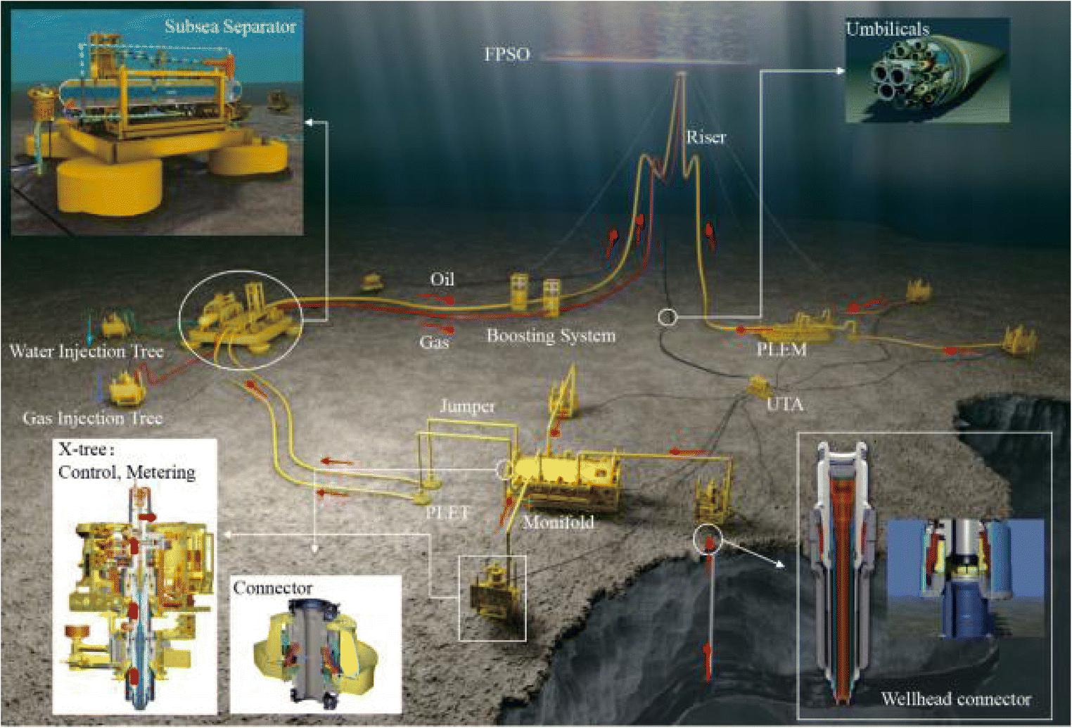 Figure 1 Typical configuration of a subsea production system (Duan et al. 2018)
One of the challenges that subsea production structures face as they move to ultra-deep water and polar underwater equipment is to design subsea shell structures capable of withstanding high external pressure.
The various purposes of pressure vessels, which have been widely used in ocean engineering such as in submersibles, underwater structures, and cylindrical with hemisphere ends, are mostly preferable and suited for bearing hydrostatic loads.
The successful study of applied operations for underwater pressure chambers such as an unmanned underwater vehicle (pressure housing) has been carried out. This investigation has been made on the basis of the buckling analysis and yielding analysis to ensure safety through analytical empirical formula by Finite Element Analysis (FEA) which have been operating at a depth of 6000 m (Joung et al. 2008) and an investigation into the design procedures of pressure vessels used in subsea blowout preventers. The design is based on resistance and load factors experienced by preventers being subjected to hydrostatic pressure at a depth of 3000 m (Cai et al. 2013).
Previous investigations into this area have been conducted with varying degrees of success. A cylindrical shaped submarine constructed from aluminum alloy achieved an operational depth of 4500 m. The titanium alloy-made, Nautile, was designed to achieve depths of 6000 m, while Trieste, with its steel pressure hull in the shape of a sphere, set a record depth of 10 900 m (Smith 1991). Exploration into different material options and methods of fabrication has been looked into during previous investigations.
Due to the deep sea's high-pressure environment, thin-walled shell structure fails to buckle when it is subjected to external pressure, inducing shell collapse owing to the buckling and leading to a failure of stability. Many researchers have considered various geometries of both stability and instability of thin shells under external pressure. Ross (2011) has extensively investigated and studied the instability of thin shells such as cylinder/cone/dome (including hemispherical) pressure hulls and pressure vessels. Yamamoto et al. (1989) investigated the general instability of stiffened cylindrical shells. However, the predicted external pressure of 1000 m is still one of the greatest challenges that researchers face in designing subsea structures, such as manifold, jumper, Christmas tree, and pipelines.
One of the major failures of previous attempts has been elastic-plastic collapse through a combination of buckling instability and material plasticity. Nonlinear, geometric effects related to material imperfections and significant displacements are another cause of failure mode (MacKay et al. 2011). This particular design method is similar to those used in offshore oil and gas installations. Here, it is essential for the accurate prediction of the pressure at which a critical collapse will occur in flexible risers operating in ultra-deep seas (Li et al. 2018). The influence on the buckling pressure should be considered and taken into account in the design process. Moreover, numerous studies have shown that spherical shells under external pressure are very sensitive to geometric imperfections.
Several reports have indicated that spherical shells exhibit imperfections under these extreme pressures. Wagner et al. (2018) and Tall et al. (2018) have reported on imperfection sensitivity of spherical shells under external pressure. Pranesh et al. (2017) investigated both perfect and imperfect thin spherical pressure hulls. There has been plenty of research and experimentation to test various high-pressure models (Boote et al. 1997; Cho et al. 2018; Ghanbari Ghazijahani et al. 2014; Gong et al. 2012; Zhang et al. 2018; Cui 2018). From their experimental investigations, a general understanding has emerged as to the cause of pressure failures on cylinders, and various recommendations and guidance have been presented.
One such recommendation is that of the ring-stiffened cylinder. This has proved to be an important advance in the improvement of structural integrity. The investigation is based on ring stiffeners to protect structures from collapse or buckling under external pressure (Bai et al. 2017; Cho et al. 2018; Ross 2011). Therefore, an efficient design of cylindrical shells is strongly recommended for stiffened cylindrical construction in order to improve buckling strength. However, unstiffened shell requires a large thickness (including layered systems of various materials) to avoid buckling. Thus, in the subsea function chamber (SFC), structure has been considered to need stiffening by five equally spaced inner stiffeners to withstand high pressure.
Experimental and numerical work studies on cylindrical shells supported by stiffeners under external pressure have been performed to reveal the importance of stiffeners to withstand high pressures (Ghanbari Ghazijahani et al. 2014; Ross and Waterman 2000).These extensive experimental and numerical works contribute in building an improved design for structural capacity of shell under external pressure. With this solution, it is essential to be able to predict the precise pressure at which ring-stiffened cylinders will collapse (Cho et al. 2018).
Another piece of research, conducted by He et al. (2014), used a finite element method to observe how thick-walled steel pipes behaved under pressure. Breddermann et al. (2016) investigated the additive manufacture and found the capability of the building pressure housings, which use 3D printer systems to build hemispheres. They proved to be made of titanium and ceramic, which was expected to resist the external pressure of 10 MPa. Furthermore, the buckling has started at 6 MPa, and the stiffened titanium hemisphere collapsed at 30 MPa, while it had been expected to withstand 24 MPa. The ceramic hemisphere could not be tested to collapse.
The buckling effect of thin cylindrical and hemispherical structures has been investigated in recent years. In particular, those structures that exhibit nonuniform thickness or geometrical imperfections seem to have attracted the attention of several researchers (Galletly et al. 1987; Hashemian and Mohareb 2016; Hsu et al. 2005; Le Grognec et al. 2009; Nguyen et al. 2009; Pan and Cui 2010; Tian et al. 1999).
Research documented by Teng (1996) provides a review of some of the most fundamental aspects of shell buckling as well as the advances and trends in this particular area. Błachut (2009) conducted an experimental investigation and carried out numerical calculations of both axisymmetric and 3D to examine the static stability of external pressure hemispherical and semispherical domes along with hybrid walls of configurations materials. He noted the possibility of achieving the necessary resistance to pressure by using a combination of layer thickness and materials.
Buckling and collapse under external pressure is often the governing design parameter for subsea structures such as pipelines; this has been widely studied by numerous researchers. Thin-walled cylinder collapse is predominantly influenced by three factors (Ventsel and Krauthammer 2002):
1) The ratio of its outer diameter compared to its thickness D/t;
2) Its material properties (yield stress, strain, etc.);
3) Any initial imperfections.
The aim of this study is to analyze and investigate thin-walled structure stability. This will be done through performing strength analysis to achieve an accurate prediction of collapse pressure of SFC, in which both initial imperfections and structural param are taken into consideration. Initial imperfections assessed using nonlinear buckling analysis have been conducted to investigate the risk of buckling as well as any risks associated with variations of thickness in the structure.
2 Subsea Function Chamber Model
A subsea function chamber (SFC) is designed to operate dry and wet tree systems, which is formulated to be placed on a wellhead, and is an essential part of a new generation of subsea production systems (see Figures 2 and 3). It is a type of subsea pressure vessel or pressure housing made of shells of cylinders with hemispherical and plate end closures that are connected to a subsea manifold through riser. It is integrated with the feature of vertical integration of equipment, into deep sea water, which has been proposed in the design of SFC. The arrangement of SFC system is shown in Figure 4.
 Figure 2 Schematic diagram of a new generation of subsea production system (Duan, 2015)
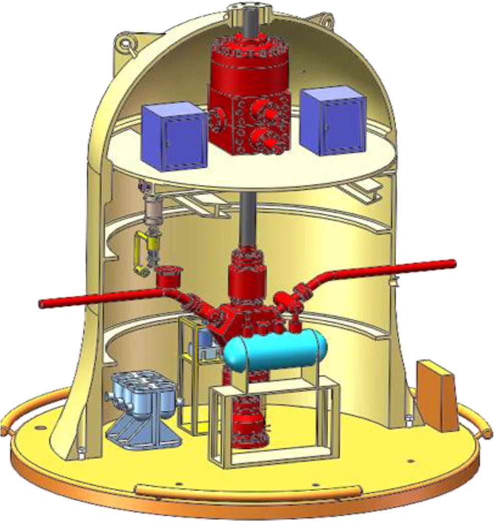 Figure 3 Artificial intelligence based new generation of a subsea production system based on SFC
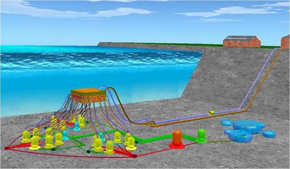 Figure 4 An efficient and economical schematic diagram for subsea deepwater oil and gas fields (Duan, 2015)
Due to the complexity of installations and connections of subsea production equipment and massive structures in a challenging environment, SFC is expected to improve and overcome potential challenges such as safety concerns, reliability and the development cost of oil fields, to reduce the subsea production systems connections and to offer significant economic benefits. Hence, SFC is designed to withstand an external pressure of 10 MPa, particularly when it is deployed in ultra-deep waters.
The deployment of SFC in offshore fields can explore new horizons to solve the technical problems and challenges that occur during installation and connection of subsea structures in ultra-deep water and in polar subsea. Therefore, SFC is composed of cylindrical and hemispherical shaped steel material, with the length of the cylindrical shell of 7000 mm and an outer diameter (to cylinder and hemisphere) of 6000 mm. It is connected to a floating new generation subsea manifold (see Figure 5). Given the challenges of operating in ultra-deep waters and the huge pressures that materials and components have to undergo, simply maintaining installations is difficult.
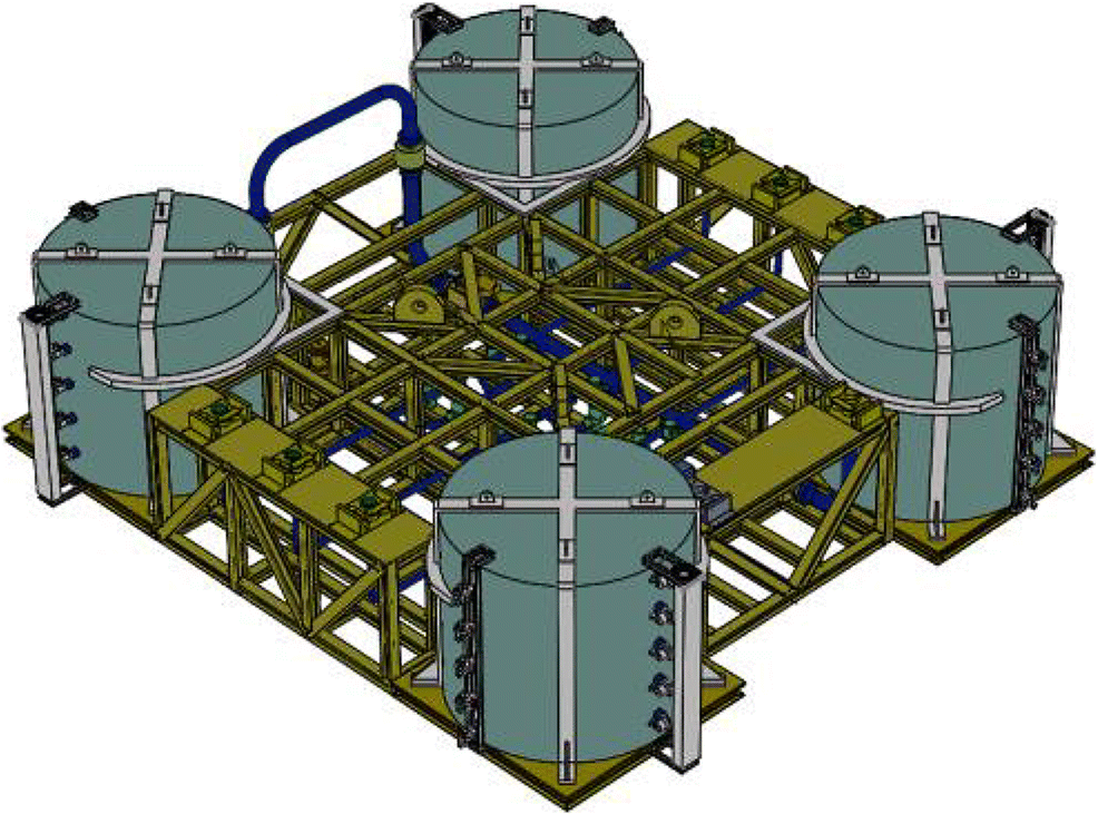 Figure 5 New generation subsea manifold
2.1 SFC Distribution Layout and Architecture
2.1.1 Wet or Dry
The subsea production system (SPS) has been extended from the early existing platforms. The tree installation location allows the decision of dry or wet production system. The field development mainly depends on the water depth. The height of subsea structures is the limitation for the shallow water depths. The installation of subsea tree along with the other major structures is not possible for water depths less than 30 m. The wet systems are expensive, and overall expenditures for such well systems are becoming the real challenge in this area. Dry trees with jacket platforms are suitable for such kind of shallow waters.
2.1.2 Horizontal or Vertical
Traditional distribution layout of subsea production systems used in the offshore environment is not appropriate. Specialized equipment is required for the development of subsea production system. Expensive vessels and special vessels are needed for the deployment of these systems, and these vessels are equipped with other diving equipment that is used for shallow waters and the remote control vehicles for ultra-deep waters. The offshore environmental conditions are necessary to handle for payload installation techniques.
This is the new concept of the compact vertical layout of the integral all-subsea system put forward based on SFC. Due to the sophisticated equipment system, heavyweight, multiple subsea connection points and high installation cost, the total cost of offshore installation not only accounts for more than 30% of the overall oil and gas field development but also reduces the safety and reliability of the system and increases the risk of offshore construction (Bai and Bai 2018).
2.2 Large Shell Structures Against Buckling
2.2.1 Thin-Walled Structure
When subjected to pressure externally and the primary stresses are compressive, buckling instability takes places at stress levels below the yield strength or elastic limit of the respective material. These kinds of failures often occur without any warning for the collapse. The elastic analysis is founded on the fact that stresses and deflections act proportionally to the loads applied (Yamaki 1984). Failure occurs when the yield or ultimate material strength is reached. Nonetheless, experiments have revealed that the vessel's compressive forces tend towards a critical value and radial deflections start and rise fast with compressive forces' increment. A load equivalent to the critical value is conventionally adequate to result into total structural failure. The most outstanding elastic buckling characteristics are such that elastic deflections are not proportional to the applied loads; hence, the problem lies not in the determination of the load-deflection relationship but instead that getting critical collapse or buckling load expression (Zyczkowski 2005).
Multiple factors contribute to the instability, i.e., to the resulting critical pressure at which it collapses, including the material's physical properties, operating temperature, and geometrical variables such as the thickness of the shell (t), external diameter (d0), and unsupported shell length (L).
2.2.2 Large-Scale Shells of Over 10 m
Shell bucking is conventionally evident in both appearance and growth when subjected to continuous loading in the cylindrical shell's circumferential or longitudinal directions. Similar to column buckling of bars and beams, shell buckling is encountered in long, shallow (i.e., relatively thin wall thickness) vessel and tank members when the members begin to exhibit visibly large transverse displacements to an applied axial load or to an applied external pressure (or vacuum). Shell structures are considered having exhibited buckling failure when under compressive loading, the structure undergoes transitional deformation from the direction that compressive load is applied (Zhang et al. 2018).
Conventionally, the deformation occurs in a direction perpendicular to that of the applied compressive loading. The compressive load at which the initial transformation of deformation is recorded and hence point of instability is the critical buckling load. In many instances, the kind of buckling may be catastrophic, occurring without prior warning signs or it presents some early form of warning. Additionally, this kind of buckling can result into sudden structural collapse (Le Grognec et al. 2009). As a result, in designing pressure vessels, buckling failure must be put into consideration, more specifically when the vessel is in vacuum service and hence susceptible to external pressure.
Conventionally, failure theories, in reference to material strength, include Tresca or Von Mises. Theories of material failure have no specific technique for addressing issues related to instability and buckling.
Additionally, the most outstanding property of materials that affect buckling failure resistance includes Poisson's ratio and Young's modulus of elasticity. With regard to geometric param, the aspect ratio including diameter and length ratios are the most significant. Contrary to expectations, the ultimate strength has no significant role in critical buckling load prediction irrespective of the shell geometry. Typically, such failures occur at calculated compressive stresses well below the ultimate compressive stress for any shell material. Additionally, cylindrical shells' buckling occurs when structures undergo either individual or combined axial compression action, torsion, or external pressure (Teng 1996).
Buckling behavior, more especially, the critical buckling load cannot be predicted accurately using linear elastic equations. On the contrary, classical buckling theories make use of nonlinear equations used extensively in buckling behavior prediction. Nonetheless, these theories incorporate both pre- and post-buckling deformation behavior. In shallow shells where there is only a small pre-buckling curvature, equilibrium conditions by Donnell adequately describe linearized form, where the critical buckling load is computed when applicable boundary conditions are applied (Loo 1957).
$$ {\displaystyle \begin{array}{l}D{\nabla}^4\left({\nabla}^4w\right)-{\nabla}^4\Big({N}_{xx}\frac{\partial^2w}{\partial {x}^2}+2{N}_{xx}\frac{\partial^2w}{\partial x\partial y}+{N}_{xx}\frac{\partial^2w}{\partial {x}^2}\\ {}+\frac{Et}{R^2}\frac{\partial^4w}{\partial {x}^4}=0\end{array}} $$ (1) where ▽2 refers to the Laplacian operator while ▽4 represents application of ▽2 twice and 4 times for ▽8. Additionally, $ D=\frac{Et^3}{12\left(1-{v}^2\right)} $ represents the flexural rigidity of the shell.
2.2.3 Imperfections of Large Shell Structures
Multiple studies, both theoretical and experimental, have addressed roundness imperfections. These imperfection distributions on real-life structures have proved to be challenging to forecast in varying manufacturing processes. This is evident in the complexity of defining the criteria for measurement of out-of-roundness and introducing the same into numerical models. For some steel construction standards, simple formulae are proposed for determination of elastic instability shell pressure sequences of manufacturing and the imposed tolerances. More specifically, The European Convention for Constructional Steelwork (Rotter and Teng 2006), recommend a 0.5% tolerance on the nominal radius. On the other hand, the ASME code (Osage, 2012) refers to two limiting factors, that is, "out of roundness' with interior diameter check, and the 'optimum plus or minus deviation from the true circular form'." With respect to the latter, the standard details a graph that shows multiple curves with reference of dimensional ratios. The diagram allows designers to obtain the maximum allowable deviation in reference to the target geometry.
The geometric imperfections are sensitive cases as has been shown in numerous previous studies (Tall et al. 2018; Wagner et al. 2018). The thin pressure hulls were investigated for both imperfect and perfect geometric analysis (Pranesh et al. 2017). The numerical and experimental studies have been carried out under extreme external pressures by many researchers to investigate the geometric imperfections under pressure (Boote et al. 1997; Cho et al. 2018; Ghanbari, et al. 2014; Wagner et al. 2018). The guidance and precedent have been set by these researchers for the future work to analyze the geometric imperfections and collapse analysis under extreme external pressure.
3 Finite Element Modeling
Shell and ring stiffeners were modeled during the numerical analysis, with the mesh in the cylinder model being uniform. The global mesh size of 0.5 mm was determined and the eigenvalue buckling mode was taken as the first imperfection shape. The detailed views of the mesh of SFC are shown in Figure 6. The element S4R of ABAQUS is used in the finite element model. This element has the following features:
 Figure 6 Finite element mesh of the model
1) 4-node double-curve and finite-strain element
2) Reduced integration
3) Hourglass control
4) Five points of integration throughout the thickness
In this study, a two-step method is utilized. First, damage is induced and then a post-damage collapse analysis is completed. Before the first step, some initial imperfections were introduced into the models. This was done by utilizing eigenvalue buckling analyses. In addition, the initial imperfection shape is selected as the first elastic buckling mode. Lastly, for the eigenvalue buckling analysis, the bottom cylinder end was assumed to have fixed boundary conditions. The imperfection amplitude was set to be 0.1, 0.2, and 0.3 t, respectively.
3.1 Thickness Configurations
For the cylinder structures, the buckling instability pressure is usually defined as the pressure at which the structure undergoes buckling. Material properties, such as yield stress and strain hardening param, as well as initial imperfections, can have a significant impact on the buckling failure of the cylinder.
Timoshenko et al. (1962) have presented the classical elastic theory formula of buckling of cylindrical shell under uniform external pressure. By assuming the centerline extension of the ring, they studied the buckling mechanism of the ring subjected to external pressure and generalized the solution to an infinitely long cylindrical shell using the plane strain hypothesis. The buckling pressure pcr of a cylindrical shell with radius R0 and thickness h is as follows:
$$ {p}_{cr}=\frac{E}{4\left(1-{\mu}^2\right)}{\left(\frac{h}{R_0}\right)}^3 $$ (2) where μ is the Poisson's ratio and E the Young's modulus of the material. The Karman-Donnell equation is widely used to analyze thin-walled structures when they are subjected to various boundary conditions and loads. The existing research results show that the theory is accurate enough for the prediction of short- and medium-long shells. Later, Loo (1957) extended the shallow shell theory of Karman-Donnell to the long cylindrical shell subjected to large nonlinear deflection; considering the influence of initial curvature of cylindrical shells, the relationship has been established between the displacement and change of curvature. The critical buckling pressure obtained by the Donnell equation is 33% higher than the classical solution given by Timoshenko. The critical buckling pressure is solved by:
$$ {p}_{bp}=\frac{E}{3\left(1-{\mu}^2\right)}{\left(\frac{h}{R}\right)}^3 $$ (3) In this study, the designed SFC is composed of a cylinder and hemispherical cap. The cylindrical shell length is 7000 mm and the outer diameter (to cylinder and hemispherical) is 6000 mm, with a design external pressure of 10 MPa.
Common steel materials are used for the SFC, with the elastic modulus of 210 GPa; a yield strength of 507 Mpa; and Poison's ratio of 0.3. The wall thicknesses calculated by the Donnell equation and Timoshenko's classical method are 167.27 and 183.99 mm, respectively. The configuration thicknesses of the SFC were set to be 100, 150, 200, 250, and 300 mm, respectively. Here, 200 mm is used as the design thickness.
3.2 Ring-Stiffened Cylinder
Many structures apply ring-stiffened cylinders including pressure hulls. When these cylinders experience uniform pressure externally, they buckle at pressures that may be lower by a small percentage to produce equivalent vessels to undergo failure when subjected to external pressure.
The resulting mode of failure is referred to as shell instability. Efficient design of cylindrical shells is strongly recommended to stiffened cylindrical construction in order to improve buckling strength; however, unstiffened cylindrical requires large thicknesses to avoid buckling which is undesirable. Thus, the SFC structure has been stiffened by five equally spaced inner stiffeners to withstand high pressure.
The key dimensions of the stiffeners are shown in Figure 7. The T stiffening ring's width, b, and height h are equal to 300 mm. The SFC's cylinder undergoes stiffening using varying stiffeners which are recommended (see Figure 8).
 Figure 7 Cross-section of a ring-stiffened cylinder
 Figure 8 Cylinder with T-shaped stiffeners
This study puts forward an ultimate strength analysis that is based on the generalized Merchant-Rankine formula (Cho et al. (2018a) and Cho et al. (2018b)).
$$ {\left(\frac{P_c}{\rho {p}_m}\right)}^2+{\left(\frac{P_c}{p_Y}\right)}^2=1 $$ (4) where pc is the collapse pressure, pmis the local buckling pressure, pY is the yield pressure, and ρ is the knockdown factor.
3.3 Material Properties
SFC is made of high strength alloy steel, and this material is based on Johnson-Cook model (Lin et al. 2010). The stress is given by:
$$ {\sigma}_{eq}=\left(A+B{\varepsilon_{\mathrm{eq}}}^n\right)\cdotp \left(1+C\ln {\varepsilon_{\mathrm{eq}}}^{\cdotp \ast}\right)\cdotp \left(1-{T}^{\ast m}\right) $$ (5) where A, B, n, C, m are the model param; σeq is the equivalent stress; λi is the equivalent plastic strain; and ith is the nondimensionalized equivalent plastic strain rate; $ {{\dot{E}}^{\ast}}_{\mathrm{eq}}={\dot{E}}_{\mathrm{eq}}/{\dot{E}}_0 $ and $ {\dot{E}}_0 $ are the reference strain rate, $ {\dot{E}}_{\mathrm{eq}} $ is the strain rate in the experiment; T∗ = (T − Tr)/(Tm − Tr) is the nondimensionalized temperature, where Tr is the reference temperature.
Here, 293 K is taken as Tm the melting point temperature of the material, while T is the test temperature. The three terms on the right side of the equation represent the equivalent plastic strain, the effect of strain rate, and the temperature on the flow stress.
The fracture strain is given by Filonova et al. (2015):
$$ {\varepsilon}_f=\left[{D}_1+{D}_2\exp \left({D}_3{\sigma}^{\ast}\right)\right]\left[1+{D}_4\ln {\dot{\varepsilon}}_{eq}^{\ast}\right]\left[1+{D}_5{T}^{\ast}\right] $$ (6) where εf is the effective fracture strain and Di, i = 1, …, 5 are the input constants; σ∗ = σH/σeq is the triaxial stress, σH is the average stress, where ∆εeq is an integral cycle of equivalent plastic strain increment and εf is the effective fracture strain in the current time step. The damage parameter D is the damage accumulation. When the damage parameter reaches one, the damage occurs, and the material element is deleted. Table 1 summarizes the mechanical and physical properties for selected param.
Table 1 Mechanical and physical properties for selected paramName of parameter Value Density of material (kg/m3) 7800 Elasticity modulus (MPa) 210 000 Poisson's ratio 0.3 Yield stress param, A (MPa) 507 Hardening coefficient B (MPa) 320 Hardenability value 0.27 Strain rate coefficient 0 Temperature coefficient 0 Melting temperature (K) 0 Conversion temperature (K) 0 3.4 Eigenvalue Solution
Structural stability is dependent on many factors, such as boundary conditions and material, load, and geometrical imperfections of varying nature. Despite the fact that critical load figures obtained by linear buckling are not particularly conservative, linear buckling is still considered important as the eigenvalue buckling produces an estimation of the critical load that would induce buckling.
Although generally calculated as a higher value than the actual critical load, it is a good starting point for the observation of possible buckling mode shapes. The solution time for linear buckling analysis is less than that for nonlinear post-buckling analysis.
The buckling loads are calculated relative to the base state of the structure. If the eigenvalue buckling procedure is the first step in an analysis, the initial conditions form the base state; otherwise, the base state is the current state of the model at the end of the last general analysis step. Thus, the base state can include preloads, and the preloads are often zero in classical eigenvalue buckling problems.
$$ {K}^{MN}{\nu}^M=0 $$ (7) It has nontrivial solutions (Zyczkowski 2005), where, KMN is the tangent stiffness matrix when the loads are applied; vM are nontrivial displacement solutions. For evaluation of the critical load level, there are several methods available. The most straightforward is the linear eigenvalue problem:
$$ \left({K}_0^{NM}+{\lambda}_i{K}_{\Delta}^{NM}\right){\nu}_i^M=0 $$ (8) where $ {K}_{\mathit{\Delta }}^{NM} $ is the stiffness matrix corresponding to the base state, which includes the effects of the preloads. $ {K}_{\Delta }^{NM} $ is the differential initial stress and load stiffness matrix due to the incremental loading pattern; λi are the eigenvalues; $ {v}_i^M $ are the buckling mode shapes (eigenvectors); M and N refer to degrees of freedom M and N of the whole model; and i refers to the ith buckling mode.
4 Results and Discussions
In this study, eigenvalue buckling analysis, static and nonlinear buckling analysis of a 1000 m, SFC structure under external pressure are performed by using ABAQUS finite element nonlinear analysis software, considering the effects of material elastic-plastic and initial imperfections.
By considering material and geometric nonlinearity, and introducing initial structural imperfections, the ultimate load of the pressure vessel under external pressure buckling is obtained. At the same time, the initial disturbance should be applied to the nonlinear analysis, in order to help the nonlinear analysis of instability, and the initial imperfections can be defined by the initial external pressure mode obtained by the eigenvalue buckling analysis (linear buckling analysis). Finally, the critical external pressure obtained by eigenvalue buckling analysis can be used as a reference for the load applied in the nonlinear buckling analysis.
The relationship between ultimate load and thickness is obtained by changing the structure's thickness, in order to improve structural strength. Moreover, the effects of the number of stiffeners on the ultimate load of the structure are studied by designing the stiffeners inside the SFC.
4.1 Nonlinear Buckling
Riks method is used for numerical post-buckling analysis. This method predicts unstable, geometrically nonlinear collapse of a structure. Geometrically nonlinear static problems often involve buckling or collapse behavior. This is certainly the case where the load displacement response shows a negative rigidity and the structure has to release strain energy in order to maintain a state of equilibrium.
The Riks method utilizes the load magnitude as another unknown factor; it solves simultaneously for loads and displacements. For unstable problems, a load displacement response may show a behavior as shown in Figure 9. So, during the periods of response, the load and/or the displacement may decrease as the solution evolves.
 Figure 9 Typical unstable static response (Zyczkowski 2005)
4.2 Thickness Influence
Figure 10 shows a comparison chart of static analysis results of SFC at different thicknesses. The thicknesses of SFC are set to be 100, 150, 200, 250, and 300 mm, respectively. The relationship between the maximum Mises stress (average Miss stress) and thickness is obtained by extracting structures with different thicknesses; the results are shown in Figure 11.
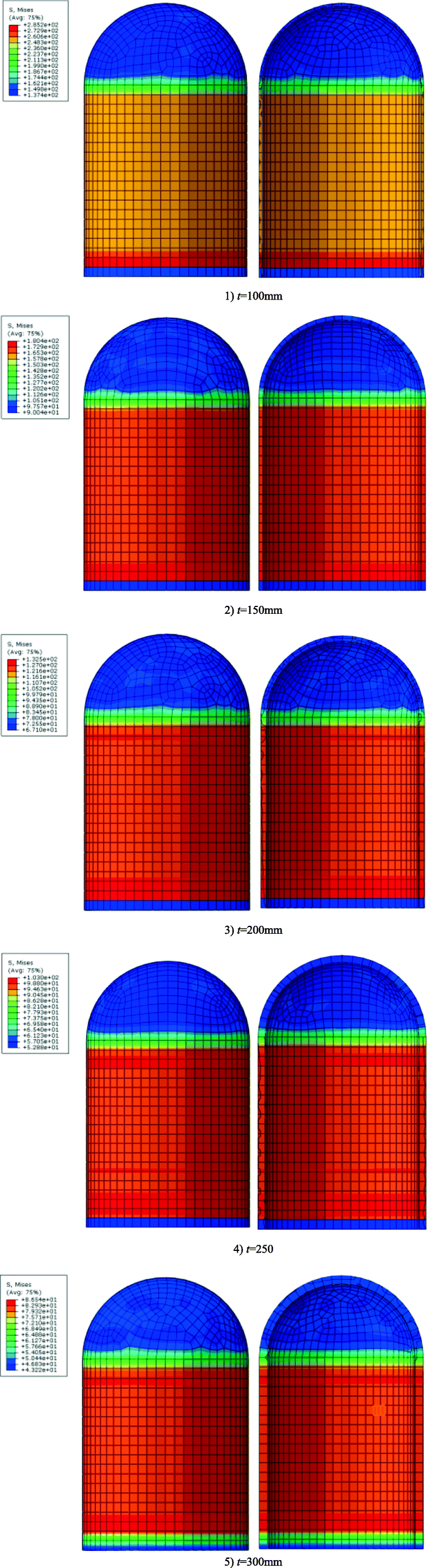 Figure 10 Von Mises stress illustration of SFC with different thicknesses
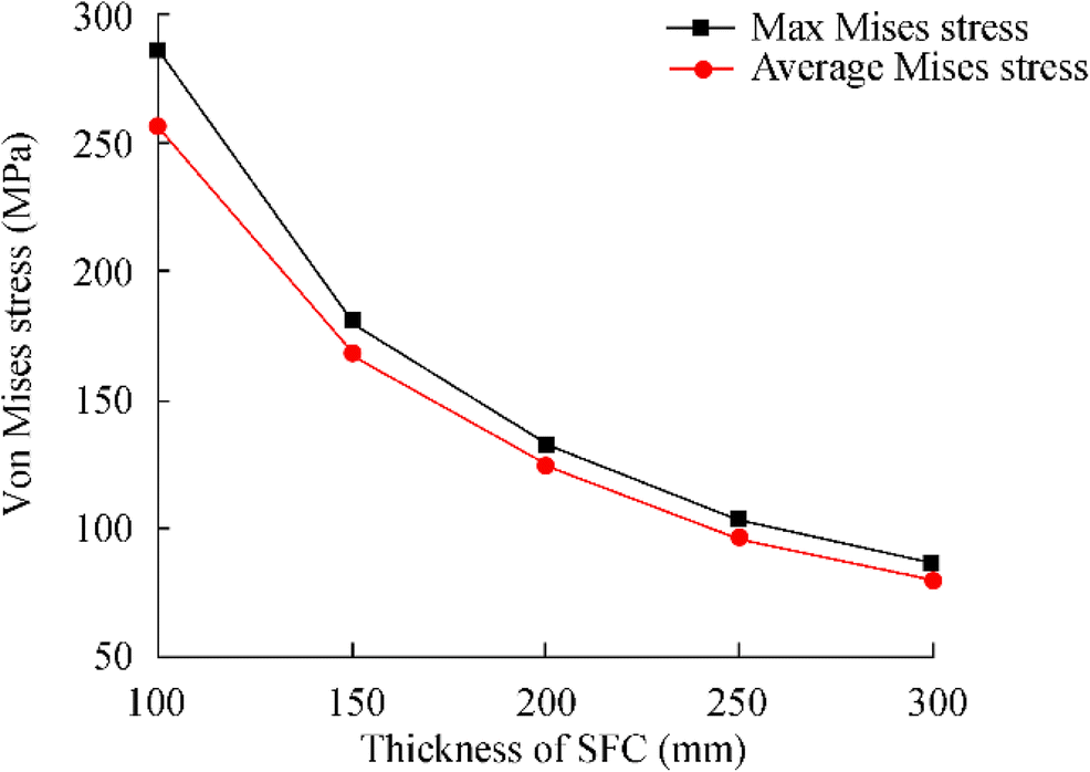 Figure 11 Von Mises stress curve of SFC with different thicknesses
4.3 Static Analysis
Static analysis is carried out with different thicknesses and the corresponding stress distribution was obtained. In Figure 10, it can be observed that the stress in the hemispherical cap of SFC is less than in the cylindrical body, which indicates that the external pressure resistance of the spherical vessel is stronger than that of the cylindrical body. The maximum von Mises stress reached was 132 MPa in a thickness of 4 mm.
Simultaneously, as can be perceived from Figure 11, the average von Mises stress of the SFC varies greatly for different thicknesses. Therefore, the thickness is very crucial for the ability of the SFC to withstand external pressure. It is indicated that the thickness estimation under the external buckling state may be too conservative. However, the stress obtained through static analysis is not suitable to the pressure vessel equipment under external pressure. Furthermore, linear buckling and nonlinear buckling analysis of the SFC are required to obtain the ultimate load of the SFC at different thicknesses.
The linear buckling analysis which is similar to modal analysis is considered and is also known as eigenvalue-based buckling analysis. The linear buckling analysis is very easy to execute, but limited results are obtained by this analysis. In this work, linear buckling analysis of the SFC is carried out.
Figure 12 shows the first five eigenvalue curves of the SFC at different thicknesses. The first and second eigenvalues of the SFC are basically the same, as are the third and fourth. As the thickness increases, the relationship between the eigenvalue and the thickness is nonlinear. The greater the thickness, the greater the curvature of the curve. The ultimate external pressure of the SFC in linear buckling analysis can be obtained by eigenvalues and applied loads.
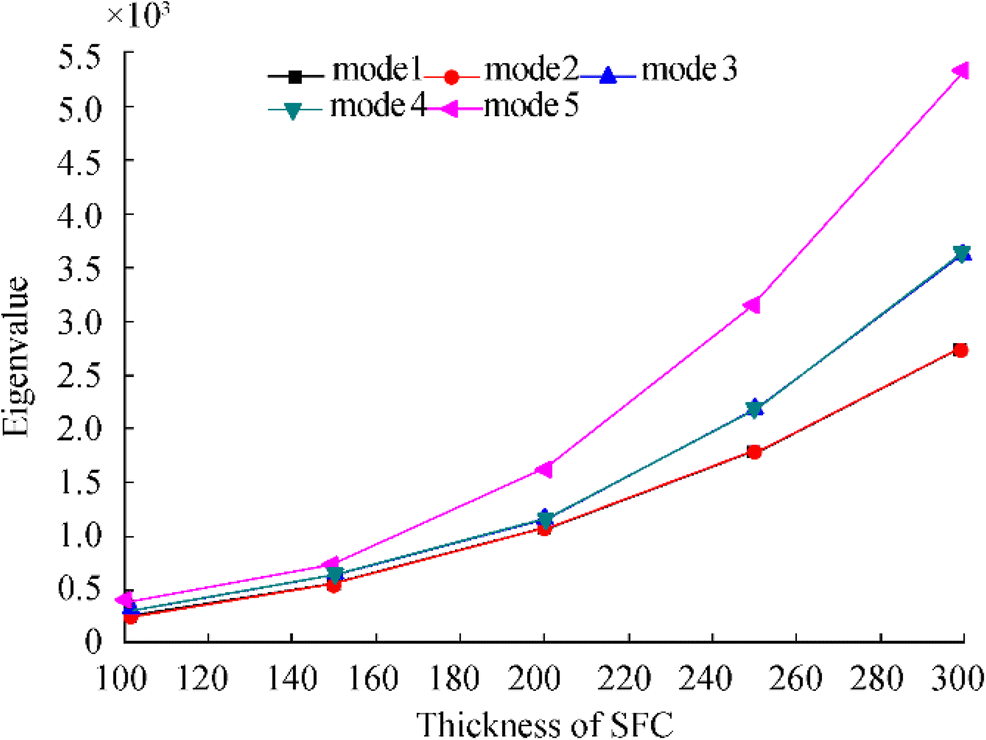 Figure 12 First five eigenmode of SFC with different thicknesses
The first five buckling modes of the SFC are extracted separately as shown in Figure 13, and the eigenvalues of the corresponding buckling modes under different thicknesses are extracted as shown in Table 2.
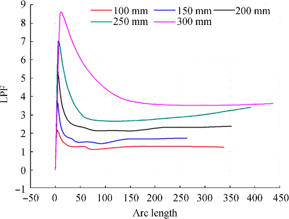 Figure 13 Nonlinear buckling analysis of LPF curves with different thicknessesTable 2 First five eigenmode of SFC at different thicknesses
E*
T (mm)Mode
1Mode
2Mode
3Mode
4Mode
5100 264.97 266.79 298.53 299.25 375.25 150 560.58 561.78 648.33 650.36 732.26 200 1095.4 1097 1155.1 1156 1618.9 250 1793 1793.8 2184.1 2184.4 3166.2 300 2757.4 2758.9 3632.1 3632.2 5332.1 Having the results of linear buckling analysis, the mode shapes are extracted as the initial imperfections of the nonlinear buckling analysis. Furthermore, through the nonlinear analysis that used Riks method, the ultimate external pressure load of the SFC can be obtained by extracting the load proportion factors (LPF) of different models and obtaining the extreme load points of the nonlinear buckling analysis.
The relationship between LPF curve and thickness, obtained by nonlinear analysis of different thicknesses, is shown in Figure 14. With the increase in thickness, the external pressure load of SFC has a linear relationship with the thickness. The ultimate external pressure load calculated by nonlinear buckling greatly exceeds the design pressure of SFC, which indicates that the thickness of the SFC calculated by pipeline buckling is too conservative.
 Figure 14 First five buckling modes obtained from linear buckling analysis (t = 200 mm)
The ultimate external pressure load of the SFC with different thicknesses is calculated by linear and nonlinear buckling analysis as shown in Table 3.
Table 3 Comparison of ultimate external pressure estimation in static analysis, linear, and nonlinear buckling analysisThickness (mm) Static analysis Linear buckling Nonlinear buckling 100 18.1 26.49 22 150 28.17 56.06 36 200 38.41 109.54 54 250 49.71 179.3 70 300 58.61 275.74 85 The external pressure varying with the thickness is illustrated in Figure 15. The static analysis of the ultimate external pressure load is obtained by comparing the maximum von Mises stress with the yield stress of the material by applying different external pressure loads to the SFC. When the maximum von Mises stress reaches the yield limit, the applied external pressure is the ultimate external pressure load.
 Figure 15 Estimation of external pressure varying with the thickness
Linear buckling is obtained by multiplying the eigenvalue by the real load, while the nonlinear buckling is obtained by multiplying the extracted maximum LPF value by the applied load. It can be seen that the linear buckling numerical error is obvious and the static analysis with the nonlinear buckling analysis are obtained. The load value and the thickness are almost linear, and the values are almost close to each other.
4.4 Stiffener Influence
It is well known that pressure vessels are unsafe under external pressure. Changing the thickness of the SFC can enhance its external pressure resistance. From the previous section, the buckling behavior of SFC was affected by initial imperfections and thickness variations. Moreover, increasing the thickness of SFC can lead to an increase of buckling pressure, caused by weight increase and cost.
Stiffening rings will be more efficient to resist buckling when they are placed in the inside of a SCF's cylinder. An increased number of stiffeners lead to an increase in weight. In practice, without changing the thickness of the SFC, stiffeners can be added to enhance the external pressure resistance of the pressure vessel to a certain extent.
There are a variety of structural forms of stiffeners. In this study, the structural forms of stiffeners are not analyzed, but the influence of the different numbers of stiffeners on the ultimate bearing capacity is analyzed.
By controlling the thickness of SFC to 200 mm and changing the number of internal stiffeners, static analysis is conducted to obtain the corresponding stress illustration diagram.
It can be noted from observation of Figure 16 that the stiffeners have a certain strengthening effect on the SFC under static calculation and the stress reduction is clear in the area with stiffeners. However, the enhancement effect on the overall von Mises stress reinforcement is not clear.
 Figure 16 Von Mises stress illustration of SFC number of stiffeners
As can be observed from Figure 17, under static analysis, the reinforcement effect of stiffeners on the structure is not clear. The average von Mises stress of SFC can be reduced by around 3% with each additional stiffener. Figure 18 shows the relationship between von Mises stress in SFC and the axial position. The von Mises stress value decreases significantly at the reinforced stiffened positions.
 Figure 17 Von Mises stress curves with different numbers of stiffeners
 Figure 18 Axial distribution curve of Mises stress with different numbers of stiffeners
The boundary condition of SFC is fixed support constraint (see Figure 19), so the stress value at the lower boundary decreases sharply, and the reinforcing stiffeners do not increase the thickness of SFC significantly.
 Figure 19 Finite element model and under pressure, mesh, and boundary condition
Through the linear buckling analysis of SFC, it is necessary to further refine the mesh to prevent the occurrence of mesh distortion due to the stiffeners. The first five buckling modes of SFC with stiffener reinforcement are extracted, based on the linear buckling analysis of the SFC, as shown in Figure 20.
 Figure 20 Linear buckling analysis of five modes of SFC with stiffeners
Compared with those without stiffener reinforcement, the other buckling modes are roughly the same as those without stiffeners except for the fifth mode shape. The data obtained by extracting the first five Eigenvalues of different numbers of stiffeners are shown in Table 4 and Figure 21.
Table 4 Fifth-order eigenvalue of SFC with stiffenerNo. First Second Third Fourth Fifth 0 1095.4 1097 1155.1 1156 1618.9 1 1221.4 1221.4 1332.1 1332.1 1693.2 2 1401.3 1401.3 1661.6 1661.6 2088.6 3 1496.9 1496.9 1862.4 1862.4 2516.3 4 1644.3 1644.3 2141.5 2141.5 2943.8 5 1807.2 1807.2 2425.9 2425.9 3126.2  Figure 21 First five eigenvalue of SFC with stiffener number
It can be observed that the stiffeners have some influence on the ultimate buckling load under the linear buckling calculation. In static analysis, a stiffener can increase the ultimate load of SFC by around 3%.
In the case of the same thickness, the model with stiffeners has around 10% stronger ability to resist external pressure than the model without stiffeners, and with the increase of the number of stiffeners, the ability to resist external pressure increases by around 10% for each stiffener.
The reinforcement stiffeners were designed for a SFC thickness of 200 mm. The relationship of the LPF curve in different numbers of stiffeners is obtained from nonlinear analysis as shown in Figure 22.
 Figure 22 LPF curve of different numbers of stiffeners
Figures 23 and 24 are a nonlinear buckling failure illustration of SFC with and without stiffeners. There are some differences between the failure modes of the two structures. Without stiffeners, SFC collapsed directly from one point into a pit. With stiffeners, the SFC from two points collapsed into two pits. With the increase of the number of stiffeners, there is a linear relationship between the ultimate external pressure load of SFC and the number of stiffeners. Under the nonlinear analysis, the ultimate load enhancement of the stiffener to SFC is around 2.5%~3%.
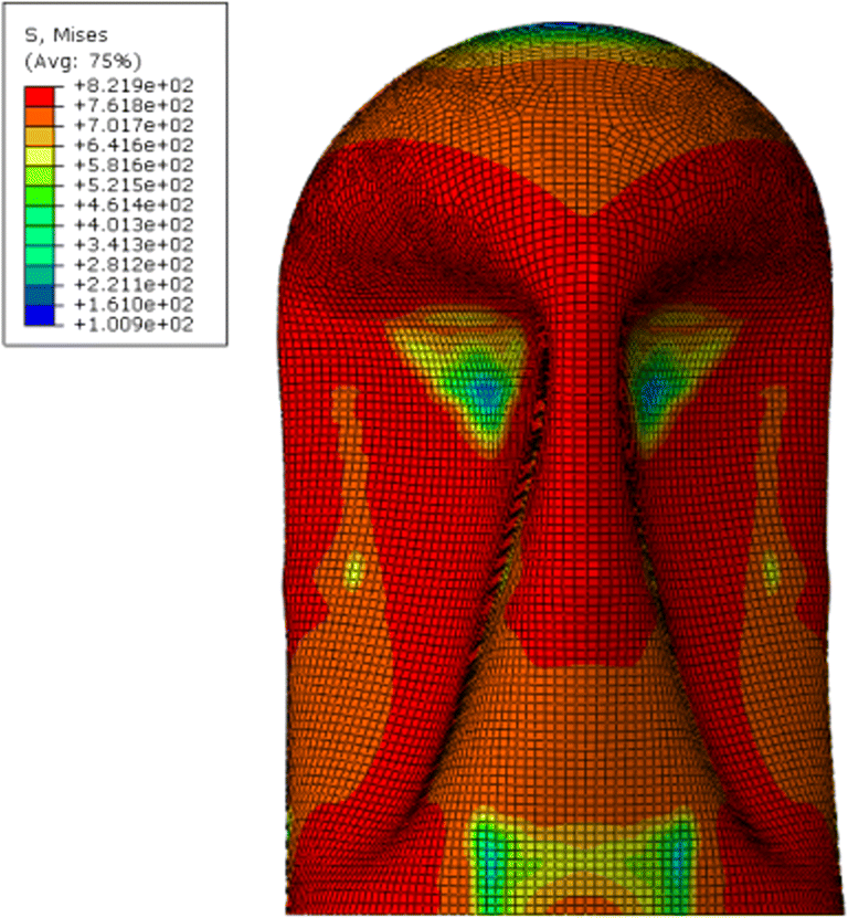 Figure 23 Illustration of nonlinear buckling failure (stiffened SFC)
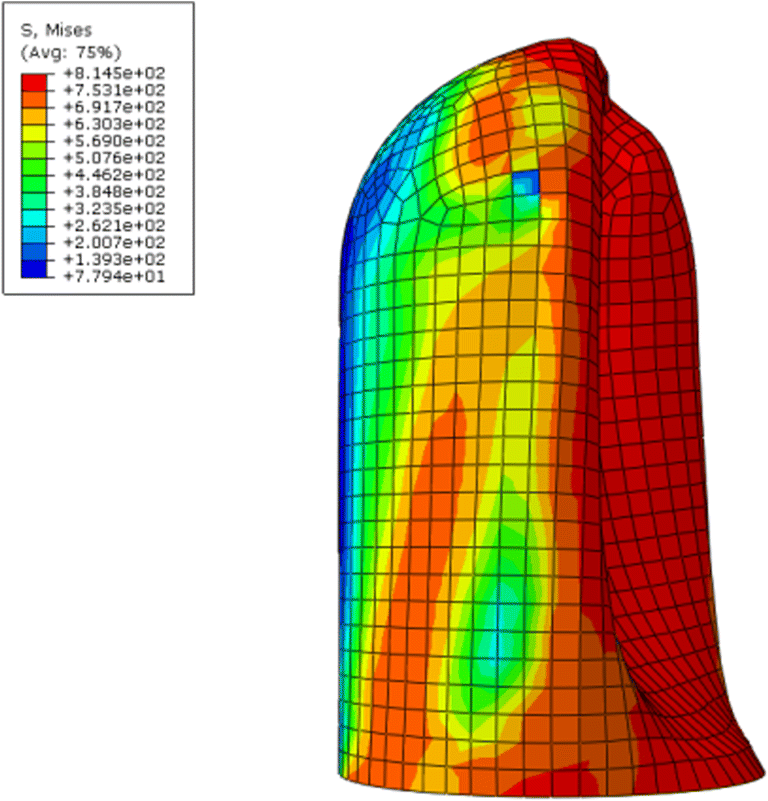 Figure 24 Illustration of nonlinear buckling failure (unstiffened SFC)
Table 5 shows the estimated value of the ultimate external pressure load obtained by static analysis, linear buckling analysis, and nonlinear buckling analysis by changing the number of stiffeners with the fixed thickness of the SFC at 200 mm.
Table 5 The estimated values of the ultimate external pressure of different stiffenersNumber of stiffeners with 200 mm in thickness Static analysis Linear buckling Nonlinear buckling 0 32.5 109.54 54 1 32.5 122.14 56.3 2 32.4 140.13 58.8 3 32.9 149.69 59.8 4 33.6 164.43 61.5 Figure 25 shows the yield strength curve. The yield strength in static analysis is obtained by applying different external pressure loads on SFC and comparing the maximum Mises stress with the yield stress of the material. When the maximum Mises stress reaches the yield limit, the external pressure applied is the yielding strength.
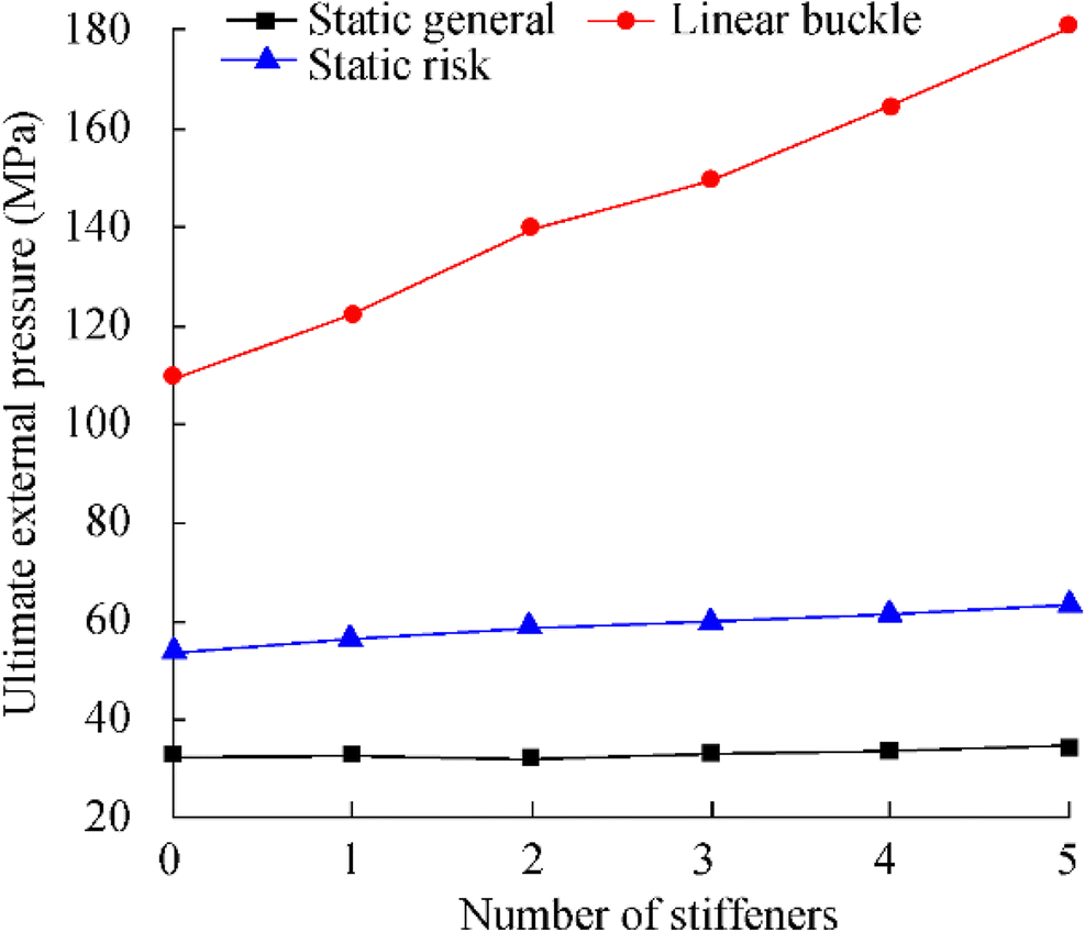 Figure 25 Estimation of ultimate external pressure in static analysis, linear buckling analysis, and nonlinear buckling analysis
Linear buckling is obtained by multiplying the Eigenvalue by the actual load, whereas the nonlinear buckling is obtained by multiplying the maximum LPF value extracted with the applied load. It can be observed that the numerical error of linear buckling is relatively obvious. The numerical value of ultimate load obtained by static analysis and nonlinear buckling analysis almost presents a linear relationship with the thickness, and the enhancement of the external pressure bearing capacity of the stiffeners to SFC is not clear.
4.5 Imperfections Influence
Generally, two techniques are used in the determination of the cylinder shell's critical buckling load. First are the deterministic methods that use multiple statistical param. While the deterministic approach undertakes the analysis based on physical laws, probabilistic/stochastic approaches mimic multiple unknown factors that impact on the critical buckling load such as profile imperfection. The sensitivity of buckling loads to small initial geometric imperfection observed from nonlinear buckling analysis was shown that the buckling load of optimally shaped cylinder is strongly influenced by the amplitude of the imperfection. The imperfection amplitude was set to be 0.1, 0.2, and 0.3 t, respectively. The critical buckling pressure obtained by the Donnell equation is 33%. Most notably also is the fact that deterministic approaches fail to account for shell wall thickness perturbations, which exist in real life.
5 Conclusions
The effect of external pressure on the SFC structural behavior of confined cylinders under uniform external pressure is investigated with linear and nonlinear finite elements methods by using ABAQUS which is a general purpose program with a finite element.
The analysis considers nonlinear geometry, through a large-strain description of the deformable medium, as well as inelastic material behavior. The numerical model of SFC under external pressure was established and the Eigenvalue buckling analysis is carried out. The effects of the thickness of different models and the number of stiffeners on the buckling modes are discussed respectively.
By introducing the nonlinear properties of materials, the nonlinear numerical model of SFC is established. The effects of stiffeners and the thickness of different models on the nonlinear buckling of stiffeners are also discussed. The following conclusions are drawn:
1) The wall thicknesses calculated by the Donnell equation and the classical solution given by Timoshenko are 167.27 and 183.99 mm, respectively. For the top hemispherical shell, the ratio of length to diameter of the cylindrical part is close to one. When its bottom is completely constrained, it has a strong ability to withstand external pressure. The classical solutions given by Donnell and Timoshenko equations are more accurate for structures with larger length and diameter.
2) The thickness has a great influence on the ultimate buckling external pressure load of SFC structure. The ultimate external pressure load of SFC has a linear relationship with the thickness, without an increase of 50 mm, and the bearing capacity of SFC increases by about 30%.
3) The Eigenvalue buckling pressure increases with the increase of modal order. The number of stiffeners will have a certain impact on the ultimate bearing capacity of the SFC structure, but the enhancement effect is not very large. Moreover, with the average increase of single stiffeners, the carrying capacity of SFC increases by around 3%.
Acknowledgment: The authors would like to acknowledge the financial support of the National Key Research and Development Plan of China (Grant no. 2016YFC0303702), National Natural Science Foundation of China (Grant no. 51879271), the 111 Project (B18054), CNPq and FAPERJ of Brazil, and China Scholarship Council (CSC). -
Figure 1 Typical configuration of a subsea production system (Duan et al. 2018)
Figure 2 Schematic diagram of a new generation of subsea production system (Duan, 2015)
Figure 3 Artificial intelligence based new generation of a subsea production system based on SFC
Figure 4 An efficient and economical schematic diagram for subsea deepwater oil and gas fields (Duan, 2015)
Figure 5 New generation subsea manifold
Figure 6 Finite element mesh of the model
Figure 7 Cross-section of a ring-stiffened cylinder
Figure 8 Cylinder with T-shaped stiffeners
Figure 9 Typical unstable static response (Zyczkowski 2005)
Figure 10 Von Mises stress illustration of SFC with different thicknesses
Figure 11 Von Mises stress curve of SFC with different thicknesses
Figure 12 First five eigenmode of SFC with different thicknesses
Figure 13 Nonlinear buckling analysis of LPF curves with different thicknesses
Figure 14 First five buckling modes obtained from linear buckling analysis (t = 200 mm)
Figure 15 Estimation of external pressure varying with the thickness
Figure 16 Von Mises stress illustration of SFC number of stiffeners
Figure 17 Von Mises stress curves with different numbers of stiffeners
Figure 18 Axial distribution curve of Mises stress with different numbers of stiffeners
Figure 19 Finite element model and under pressure, mesh, and boundary condition
Figure 20 Linear buckling analysis of five modes of SFC with stiffeners
Figure 21 First five eigenvalue of SFC with stiffener number
Figure 22 LPF curve of different numbers of stiffeners
Figure 23 Illustration of nonlinear buckling failure (stiffened SFC)
Figure 24 Illustration of nonlinear buckling failure (unstiffened SFC)
Figure 25 Estimation of ultimate external pressure in static analysis, linear buckling analysis, and nonlinear buckling analysis
Table 1 Mechanical and physical properties for selected param
Name of parameter Value Density of material (kg/m3) 7800 Elasticity modulus (MPa) 210 000 Poisson's ratio 0.3 Yield stress param, A (MPa) 507 Hardening coefficient B (MPa) 320 Hardenability value 0.27 Strain rate coefficient 0 Temperature coefficient 0 Melting temperature (K) 0 Conversion temperature (K) 0 Table 2 First five eigenmode of SFC at different thicknesses
E*
T (mm)Mode
1Mode
2Mode
3Mode
4Mode
5100 264.97 266.79 298.53 299.25 375.25 150 560.58 561.78 648.33 650.36 732.26 200 1095.4 1097 1155.1 1156 1618.9 250 1793 1793.8 2184.1 2184.4 3166.2 300 2757.4 2758.9 3632.1 3632.2 5332.1 Table 3 Comparison of ultimate external pressure estimation in static analysis, linear, and nonlinear buckling analysis
Thickness (mm) Static analysis Linear buckling Nonlinear buckling 100 18.1 26.49 22 150 28.17 56.06 36 200 38.41 109.54 54 250 49.71 179.3 70 300 58.61 275.74 85 Table 4 Fifth-order eigenvalue of SFC with stiffener
No. First Second Third Fourth Fifth 0 1095.4 1097 1155.1 1156 1618.9 1 1221.4 1221.4 1332.1 1332.1 1693.2 2 1401.3 1401.3 1661.6 1661.6 2088.6 3 1496.9 1496.9 1862.4 1862.4 2516.3 4 1644.3 1644.3 2141.5 2141.5 2943.8 5 1807.2 1807.2 2425.9 2425.9 3126.2 Table 5 The estimated values of the ultimate external pressure of different stiffeners
Number of stiffeners with 200 mm in thickness Static analysis Linear buckling Nonlinear buckling 0 32.5 109.54 54 1 32.5 122.14 56.3 2 32.4 140.13 58.8 3 32.9 149.69 59.8 4 33.6 164.43 61.5 -
ASME (1989) Boiler and Pressure Vessel Code published on CD-ROM. Ⅷ, American Society of Mechanical Engineers. Bai Y, Bai Q (2018) Subsea engineering handbook. In Subsea Engineering Handbook https://doi.org/10.1016/C2016-0-03767-1 Bai X, Xu W, Ren H, Li J (2017) Analysis of the influence of stiffness reduction on the load carrying capacity of ring-stiffened cylindrical shell. Ocean Eng 135: 52–62. https://doi.org/10.1016/j.oceaneng.2017.02.034 Błachut J (2009) Buckling of multilayered metal domes. Thin-Walled Struct 47(12): 1429–1438. https://doi.org/10.1016/j.tws.2009.07.011 Boote D, Mascia D, Monti M, Rizzuto E, Tedeschi R (1997) Elastic instability of thin cylindrical shells: Numerical and experimental investigation. Ocean Eng 24(2): 133–160. https://doi.org/10.1016/0029-8018(96)00004-2 Breddermann K, Drescher P, Polzin C, Seitz H, Paschen M (2016) Printed pressure housings for underwater applications. Ocean Eng 113: 57–63. https://doi.org/10.1016/j.oceaneng.2015.12.033 Cai B, Liu Y, Liu Z, Tian X, Ren C, Abulimiti A (2013) Exploratory study on load and resistance factor design of pressure vessel for subsea blowout preventers. Eng Fail Anal 27: 119–129. https://doi.org/10.1016/j.engfailanal.2012.08.020 Cho SR, Muttaqie T, Do QT, Kim S, Kim SM, Han DH (2018a) Experimental investigations on the failure modes of ring-stiffened cylinders under external hydrostatic pressure. Int J Naval Arch Ocean Eng 10(6): 711–729. https://doi.org/10.1016/j.ijnaoe.2017.12.002 Cho SR, Muttaqie T, Do QT, So HY, Sohn JM (2018b) Ultimate strength formulation considering failure mode interactions of ring-stiffened cylinders subjected to hydrostatic pressure. Ocean Eng 161: 242–256. https://doi.org/10.1016/j.oceaneng.2018.04.083 Filonova V, Liu Y, Fish J (2015) Computational simulation, multi scale computations, and issues related to behavioral aspects of HSREP: singlescale and multiscale models of polyurea and high-density polyethylene (HDPE) subjected to high strain rates. In Elastomeric Polymers with High Rate Sensitivity: Applications in Blast, Shockwave, and Penetration Mechanics : 233–256. https://doi.org/10.1016/B978-0-323-35400-4.00006-4 Galletly GD, Blachut J, Kruzelecki J (1987) Plastic buckling of imperfect hemispherical shells subjected to external pressure. Proc Inst Mech Eng C J Mech Eng Sci 201(3): 153–170. https://doi.org/10.1243/PIME_PROC_1987_201_103_02 Ghanbari Ghazijahani T, Jiao H, Holloway D (2014) An experimental study on externally pressurized stiffened and thickened cylindrical shells. Thin-Walled Struct 85: 359–366. https://doi.org/10.1016/j.tws.2014.08.023 Gong S, Sun B, Bao S, Bai Y (2012) Buckle propagation of offshore pipelines under external pressure. Mar Struct 29(1): 115–130. https://doi.org/10.1016/j.marstruc.2012.10.006 Hashemian R, Mohareb M (2016) Finite difference model for the buckling analysis of sandwich pipes under external pressure. Ocean Eng 122: 172–185. https://doi.org/10.1016/j.oceaneng.2016.06.003 He T, Duan M, An C (2014) Prediction of the collapse pressure for thick-walled pipes under external pressure. Appl Ocean Res 47: 199–203. https://doi.org/10.1016/j.apor.2014.05.006 Hsu CY, Liang CC, Shiah SW, Jen CY (2005) A study of stress concentration effect around penetrations on curved shell and failure modes for deep-diving submersible vehicle. Ocean Eng 32(8–9): 1098–1121. https://doi.org/10.1016/j.oceaneng.2004.05.011 Institution BS (1991) Structural Use of Timber: Code of Practice for Permissible Stress Design Materials and Workmanship. British Standards Institution. Joung TH, Lee JH, Nho IS, Lee CM, Lee PM, Aoki T, Hyakudome T (2008) A study on the pressure vessel design, structural analysis and pressure test of a 6000 m depth-rated unmanned underwater vehicle. Ships Offshore Struct 3(3): 205–214. https://doi.org/10.1080/17445300802204371 Le Grognec P, Casari P, Choqueuse D (2009) Influence of residual stresses and geometric imperfections on the elastoplastic collapse of cylindrical tubes under external pressure. Mar Struct 22(4): 836–854. https://doi.org/10.1016/j.marstruc.2009.09.003 Li X, Jiang X, Hopman H (2018) A review on predicting critical collapse pressure of flexible risers for ultra-deep oil and gas production. Appl Ocean Res 80: 1–10. https://doi.org/10.1016/j.apor.2018.08.013 Lin YC, Chen XM, Liu G (2010) A modified Johnson-Cook model for tensile behaviors of typical high-strength alloy steel. Mater Sci Eng A 527(26): 6980–6986. https://doi.org/10.1016/j.msea.2010.07.061 Loo T (1957) An extension of Donnells equation for a circular cylindrical shell. J Aeronaut Space Sci, (AMER INST AERONAUT). MacKay JR, Van Keulen F, Smith MJ (2011) Quantifying the accuracy of numerical collapse predictions for the design of submarine pressure hulls. Thin-Walled Struct 49: 145–156. https://doi.org/10.1016/j.tws.2010.08.015 Nguyen HLT, Elishakoff I, Nguyen VT (2009) Buckling under the external pressure of cylindrical shells with variable thickness. Int J Solids Struct 46(24): 4163–4168. https://doi.org/10.1016/j.ijsolstr.2009.07.025 Pan B, Cui W (2010) An overview of buckling and ultimate strength of spherical pressure hull under external pressure. Mar Struct 23: 227–240. https://doi.org/10.1016/j.marstruc.2010.07.005 Pranesh S, Kumar D, Subramanian VA, Sathianarayanan D, Ramadass G (2017) Non-linear buckling analysis of imperfect thin spherical pressure hull for manned submersible. J Ocean Eng Sci 2(4): 293–300. https://doi.org/10.1016/j.joes.2017.11.001 Ross CTF (2011) Pressure vessels: external pressure technology. In Pressure Vessels: External Pressure Technology (2nd Edition). https://doi.org/10.1533/9780857092496 Ross CTF, Waterman GA (2000) Inelastic instability of circular corrugated cylinders under external hydrostatic pressure. Ocean Eng 27(4): 331–343. https://doi.org/10.1016/S0029-8018(99)00035-9 Rotter JM, Teng J-G (2006) Buckling of thin metal shells. CRC Press, Boca Raton Smith CS (1991) Design of submersible pressure hulls in composite materials. Mar Struct 4(2): 141–182. https://doi.org/10.1016/0951-8339(91)90018-7 Tall M, Hariri S, Le Grognec P, Simonet Y (2018) Elastoplastic buckling and collapse of spherical shells under combined loadings. Thin-Walled Struct 123:114–125. https://doi.org/10.1016/j.tws.2017.10.041 Teng JG (1996) Buckling of thin shells: Recent advances and trends. Appl Mech Rev 49(4): 263–274. https://doi.org/10.1115/1.3101927 Tian J, Wang CM, Swaddiwudhipong S (1999) Elastic buckling analysis of ring-stiffened cylindrical shells under general pressure loading via the Ritz method. Thin-Walled Struct 35(1): 1–24. https://doi.org/10.1016/S0263-8231(99)00012-9 Timoshenko SP, Gere JM, Prager W (1962) Theory of Elastic Stability, Second Edition. J Appl Mech 29(1): 220–221. https://doi.org/10.1115/1.3636481 Ventsel E, Krauthammer T (2002) Thin plates and shells: theory, analysis, and applications. Appl Mech Rev 55(4): B72–B73. https://doi.org/10.1115/1.1483356 Wagner HNR, Hühne C, Niemann S (2018) Robust knockdown factors for the design of spherical shells under external pressure: Development and validation. Int J Mech Sci 141:58–77. https://doi.org/10.1016/j.ijmecsci.2018.03.029 Yamaki, (1984) Elastic Stability of Circular Cylindrical Shell. Elsevier Science Publishers, Amsterdam Yamamoto Y, Homma Y, Oshima K, Mishiro Y, Terada H, Yoshikawa T, Morihana H, Yamauchi Y, Takenaka M (1989) General instability of ring-stiffened cylindrical shells under external pressure. Mar Struct 2(2): 133–149. https://doi.org/10.1016/0951-8339(89)90009-9 Zhang J, Wang WM, Cui WC, Tang WX, Wang F, Chen Y (2018) Buckling of longan-shaped shells under external pressure. Mar Struct 60:218–225. https://doi.org/10.1016/j.marstruc.2018.04.002 Zyczkowski M (2005) Post-buckling analysis of non-prismatic columns under general behaviour of loading. Int J Non-Linear Mech 40(4): 445–463. https://doi.org/10.1016/j.ijnonlinmec.2004.05.014