-
Abstract
This study explored the buckling of multiple intersecting spherical shells. A three-segment spherical shell was designed using the theory of deformation coordination; the design was compared with that of a volume-equivalent cylindrical shell and ring-ribbed cylindrical shell. The numerical results indicated that the buckling capacity of the three-segment spherical shell was superior to those of the other two cylindrical shells. To validate our numerical approach, three laboratory-scale shell models were fabricated. Each model was accurately measured and slowly tested in a pressure chamber; thus, the tested shells were studied numerically. The experimental collapse modes agreed well with numerical results, and the collapse load of the three-segment pressure shell was considerably higher than that of the two cylindrical shells.-
Keywords:
- Multi-segment spherical shell ·
- Cylindrical shell ·
- External pressure ·
- Buckling
Article Highlights• Three-segment spherical shell had a superior buckling capacity compared with equivalent cylindrical shell.• A three-segment spherical shell was designed using the theory of deformation coordination.• Bucking of three-segment spherical and equivalent cylindrical shells was studied experimentally and numerically. -
1 Introduction
For many years, cylindrical and spherical pressure shells have been the simplest and most efficient deep-sea pressure shell structures. These structures play crucial roles in the development of underwater pressure vessels, such as hulls of submarines and submersibles, due to their high space utilization and simple geometry (Ross et al. 2001; Ross 2006; Pan and Cui 2010; Pan and Cui 2011; Zuo et al. 2014). However, these structures are susceptible to buckling when exposed to uniform external pressure, which is strongly affected by geometrical configuration, material properties, and geometrical imperfections (Arbocz and Starnes 2002; Błachut and Magnucki 2008; Błachut 2014; Jasion and Magnucki 2015; Zingoni 2015).
The spherical pressure shell exhibits a small buoyancy coefficient and uses less space than a cylindrical pressure shell of equal diameter (Ness and Simpson Jr 2009; Błachut and Jaiswal 2000; Liang 2006; Błachut and Smith 2008; Stanley 2012). Multiple intersecting spherical shells have the same two advantages as these two shell types (Zhang et al. 2017; Zhang et al. 2018). Garland designed and built a double-segment spherical submersible termed Deep Quest and a Deep Submergence Rescue Vehicle (Charles Garland 1968). Leon (1971) conducted an experimental study on a double-segment spherical shell with titanium alloys. The result indicated that using Al2O3 instead of titanium alloys to fabricate ring ribs increases the payload of the shells by 10%. Hall et al. developed a double-segment spherical shell by using graphite and epoxy composites, reducing the weight of the shell by 46% compared with a steel pressure shell with the same diameter (Hall et al. 1991). Liang et al. studied the optimisation design of multi-segment spherical shells under deep-water conditions (Liang et al. 2004). Gou and Cui studied the structural optimisation of multi-segment spherical pressure shells and proposed two typical failure modes (Gou and Cui 2009). However, the buckling between a multi-segment spherical pressure shell and cylindrical shell under uniform external pressure has not been compared.
In this paper, a comparison of the buckling between multiple intersecting spherical pressure shells and cylindrical shells under uniform external pressure is presented. First, the three-segment spherical shell and corresponding equivalent cylindrical and stiffened cylindrical shells were designed Subsequently, equivalent contrast shells for the three-segment spherical, volume-equivalent cylindrical, and stiffened cylindrical shells were developed in both linear and nonlinear ranges, and the geometrical nonlinearity and initial geometrical imperfections were included in nonlinear computation. Finally, the buckling performances of the three laboratory-scale models were experimentally studied. The results revealed that the load-carrying capacity of multiple intersecting spherical shells was higher than that of the cylindrical shell and stiffened cylindrical shell.
2 Problem Description
2.1 Geometries of Three-Segment Spherical Shells and Cylindrical Shells
In this study, a three-segment spherical shell was investigated as a representative structure of the multi-segment spherical pressure shell, as illustrated in Figure 1, wherein t is the thickness of the spherical shell, R is the inner radius of the any spherical shells of the three-segment spherical shell, α is the intersection angle, Lr is the width of the circumferential rib, tr is the thickness of the circumferential rib, Dr is the outer diameter of the circumferential reinforcing rib, and L is the total length of the three-segment spherical shell.
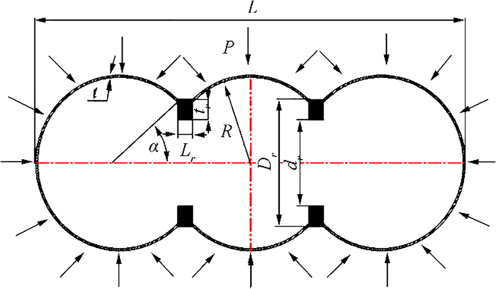 Figure 1 Geometry of the three-segment spherical pressure hull
In this study, to design the three-segment spherical, α = 45° and tr = 250 mm were selected. According to the deformation compatibility principle (Gou and Cui 2009), when the radial deformation of a multi-segment spherical shell opening is consistent with the radial deformation of the complete spherical shell opening, the rib-ring parameter combination is optimal. Related formulas are given as follows.
The radial displacement of the complete spherical shell in hydrostatic pressure:
$$ {\delta}_s=\frac{P_0{R}^2\sin \alpha }{2 Et}\left(1-\mu \right) $$ (1) where P0 is uniform external pressure, E is Young's modulus, and μ is Poisson's ratio.
The radial displacement of the rib-ring outer diameter is obtained from the following equation:
$$ {\delta}_r=\frac{P_R{D}_r}{2E}\left(\frac{D_r^2+{d}^2}{D_r^2-{d}^2}-\mu \right) $$ (2) where $ {P}_R=\frac{2F\cos \alpha }{L_r}+{P}_0 $, which is the uniform pressure on the rib-ring.
Coordinate the deformation between the spherical shell and the rib-ring; then,
$$ {\delta}_s={\delta}_{\mathrm{R}} $$ (3) Thus, the functional relationships between Dr, tr, and Lr can be presented as follows:
$$ {L}_r=\frac{R\cos \alpha }{\frac{R^2\sin \alpha \left(1-\mu \right)}{tD_r}\frac{1}{\frac{D_r^2+2{t}_r^2-2{D}_r{t}_r}{2{D}_r{t}_r-2{t}_r^2}-\mu }-1} $$ (4) where $ {D}_r=\sqrt{4{\left(R+t\right)}^2-4{R}^2\cos {\alpha}^2} $.
The design of the cylindrical shell is commonly divided into two types: no reinforcement and ribbed reinforcement. Ribbed reinforcement is generally achieved using annular ribs. To avoid the shape, size, quantity, and layout of the ribs influencing the analysis, the shape, size, quantity, and layout of cylindrical shell ribs used were identical to those of the three-segment spherical shell.
The volume, thickness, and the total length of the cabin (L) of the cylindrical shell were equal to those of the three-segment spherical shell, which can be calculated as follows:
Volume of the multi-segment spherical shell (V1):
$$ {V}_1=\pi {R}^3\left[n\cdot \frac{4}{3}-2\left(n-1\right)\left(\frac{2}{3}-\cos \alpha +\frac{1}{3}\cos {\alpha}^3\right)\right]+{V}_r\left(n-1\right) $$ (5) where $ {V}_r=\pi {\left(\frac{D_r}{2}-{t}_r\right)}^2 $ is the interior volume of the section of the rib ring.
Cylindrical shell volume of internal cavity (V2):
$$ {V}_2=\pi {\left(\frac{D_0}{2}\right)}^2\cdot \left(L-{L}_r\cdot n\right)+\pi {\left(\frac{D_0}{2}-{t}_r\right)}^2\cdot {L}_r\cdot n $$ (6) where n is the number of circumferential stiffeners and D0 is the inner diameter of the cylindrical shell.
Then,
$$ {V}_1={V}_2 $$ (7) 2.2 Numerical Analysis
The finite element method is a high-performance and commonly used numerical calculation method that can effectively solve problems related to pre-research analysis of production. The detailed parameters of geometries are presented in Table 1. The nonlinear numerical analysis was conducted using the arc length method available in ABAQUS code according to existing specifications (Eurocode 2007; China Classification Society (CCS) 2013). A uniform initial pressure, P0 = 1 MPa, is externally applied on the outer surface of each model. A three-point constraint method was employed to avoid rigid body motion, as illustrated in Figure 2, as follows: Uy = Uz = 0, Ux = Uy = 0, and Uy = Uz = 0. The mesh type of the shells was a quadrilateral shell element (S4). The numbers of three-segment spherical shell elements, cylindrical shell elements, and rib-ring cylindrical shell elements were approximately 24 600, 22 680, and 25 320, respectively. The number of elements was determined using mesh density convergence analysis, as reported in CCS (China Classification Society (CCS) 2013).
Table 1 Main parameters of three geometric modelsModel L (mm) R (mm) t (mm) Dr (mm) Lr (mm) D0 n Three-sphere shell 5086 1000 20 1470 109 N/A N/A Cylindrical shell 5086 N/A 20 N/A 0 888 0 Ring-ribbed cylindrical shell 5086 N/A 20 N/A 109 898 2 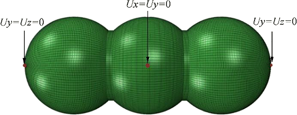 Figure 2 FE mesh and boundary condition of the three-segment spherical shell
The pressure shell of submersibles is mostly composed of high-strength metallic materials having good plastic property. Considering that the pressure shell can operate in deep-sea environments, the material should have strong corrosion resistance, high-specific strength, and high-specific stiffness; therefore, titanium alloy (TC4) was selected as the material for numerical analysis. Its properties are as follows: Young's modulus E = 110 GPa, Poisson's ratio μ = 0.3, and yield strength σs = 830 MPa. In linear analysis, multimodal buckling problems were considered. Castro et al. indicated that initial geometric imperfections play a crucial role in shell buckling analyses, and linear buckling eigenmode-shaped imperfections are commonly used to assess the effects of initial imperfections on the buckling of thin-walled structures (Castro et al. 2014). Therefore, according to ENV 1993-1-6 (2007; Eurocode 2007), the linear bucking eigenmode imperfections are introduced as initial geometric imperfections in nonlinear analysis. The magnitude of the imperfections is set to 5 mm which is the highest value allowed in the code.
3 Computational Results and Discussion
The load-carrying capacity of the three-segment spherical shell was studied in detail, and the three-segment spherical shell was compared with volume-equivalent cylindrical shells with and without rib rings. The computational results are presented in Table 2. The first column indicates that the linear buckling loads Plb of the 5th-order buckling mode of the three-segment shell varied slightly from 52.42 to 52.45 MPa. The 5th-order buckling mode of the cylindrical shell had a considerable buckling load difference. The linear buckling loads increased significantly with an increase in mode order. In the cylindrical shell, the maximum and minimum buckling loads were 9.17 and 5.60 MPa, respectively, causing a difference of 63.81%. The linear buckling load in the 5th-order buckling mode of the ring-ribbed cylindrical shell was higher than that of the 5th-order buckling mode of the cylindrical shell. The maximum buckling load of the ring-ribbed cylindrical shell was 19.62 MPa, which was 8.00% higher than the minimum buckling load. The buckling load of the three-segment shell was higher than that of the two types of cylindrical shells at all mode orders. The buckling load of the three-segment shell was 2.88% higher than that of the ring-ribbed cylindrical shell and 9.36% higher than that of the cylindrical shell in the first order.
Table 2 Critical buckling loads and circumferential waves of the three-segment spherical and cylindrical shellsBuckling eigenmode Plb (MPa) (Circumferential waves number) Three-segment spherical shell Cylindrical shell Ring-ribbed cylindrical shell 1st 52.42 (9) 5.60 (3) 18.17 (4) 2nd 52.42 (9) 5.60 (3) 18.17 (4) 3rd 52.45 (9) 8.37 (2) 19.36 (4) 4th 52.45 (9) 8.37 (2) 19.36 (4) 5th 52.45 (9) 9.17 (4) 19.62 (5) Figure 3 indicates that the three-segment shell buckling mode occurred at both ends of the shell. The buckling mode position of the cylindrical shell was the middle of the shell, while the buckling mode of the ring-ribbed cylindrical shell occurred in the middle of one end.
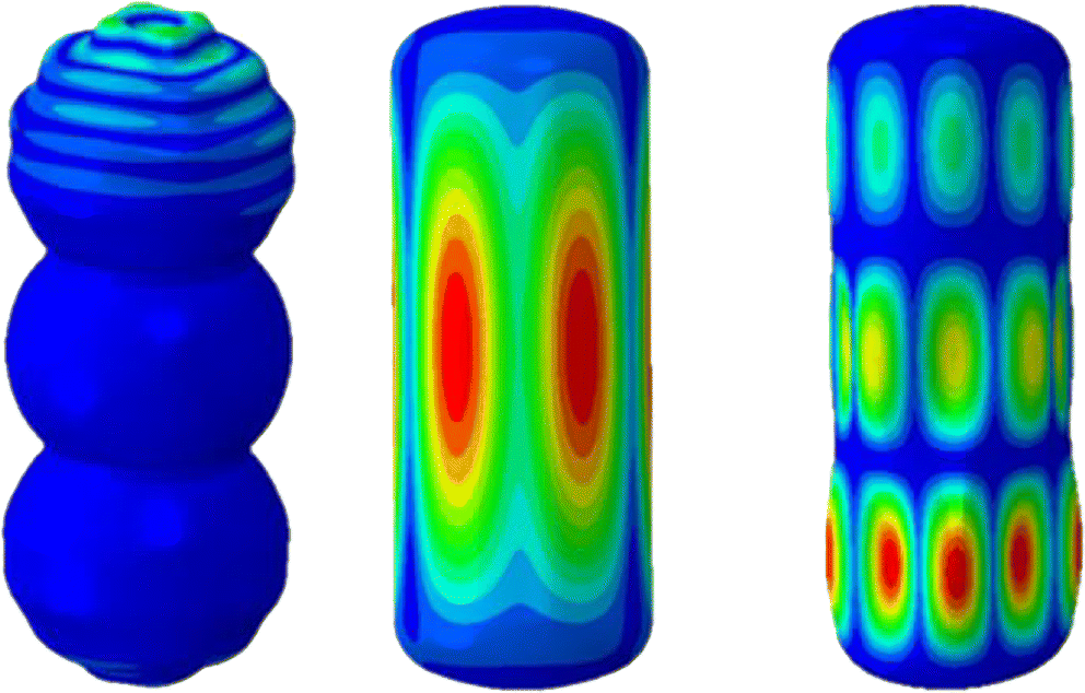 Figure 3 Buckling modes of the three-segment spherical shell and two types of cylindrical shell
The five buckling eigenmodes were determined for the three-segment shell, and the superposition of the first three eigenmode was used as the initial geometric imperfection. The superposition modes were 1st + 2nd, 1st + 3rd, 2nd + 3rd, and 1st + 2nd + 3rd, as presented in Table 3. The critical buckling loads of nonlinear buckling under the eigenmode-shaped imperfections were considerably close, ranging from approximately 17.09 to 17.92 MPa.
Table 3 Critical buckling load of the three-segment spherical shell with imperfections under different eigenmode shapesBuckling eigenmode Critical buckling load(MPa) 1st 17.09 2nd 17.63 3rd 17.14 4th 17.92 5th 17.17 1st + 2nd 14.54 1st + 3rd 13.85 2nd + 3rd 15.56 1st + 2nd + 3rd 13.54 The equilibrium paths of the three-segment spherical shell under different eigenmode-shaped imperfections are illustrated in Figure 4. The nonlinear load increased monotonically to a maximum value corresponding to the critical buckling load and subsequently decreased rapidly. For the three-segment spherical shell, the first-order buckling eigenmode-shaped imperfection was the least favourable imperfection among the first five-ordered buckling modes. Moreover, the maximum buckling load of the first three-ordered buckling superposition eigenmode-shaped imperfections occurred at 2nd + 3rd, which was 15.557 MPa, while the minimum critical buckling load occurred at 1st + 2nd + 3rd, which was 13.539 MPa. The critical buckling loads of each of the first five-ordered superposition eigenmode-shaped imperfections were considerably lower than those of any single eigenmode-shaped imperfection of the first five orders, which were initial geometrical defects. The superposition eigenmode-shaped defects were more damaging than the single eigenmode-shaped imperfections.
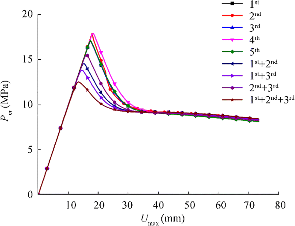 Figure 4 Nonlinear buckling equilibrium path of the three-segment spherical shell under different imperfections
Figure 5 shows collapse modes at the end of the equilibrium path. The positions of buckling failure of the three-segment shell are approximately the same (at one end of the shell), and no instability was observed in the middle of the spherical shell. This destruction is similar to that of a single spherical shell.
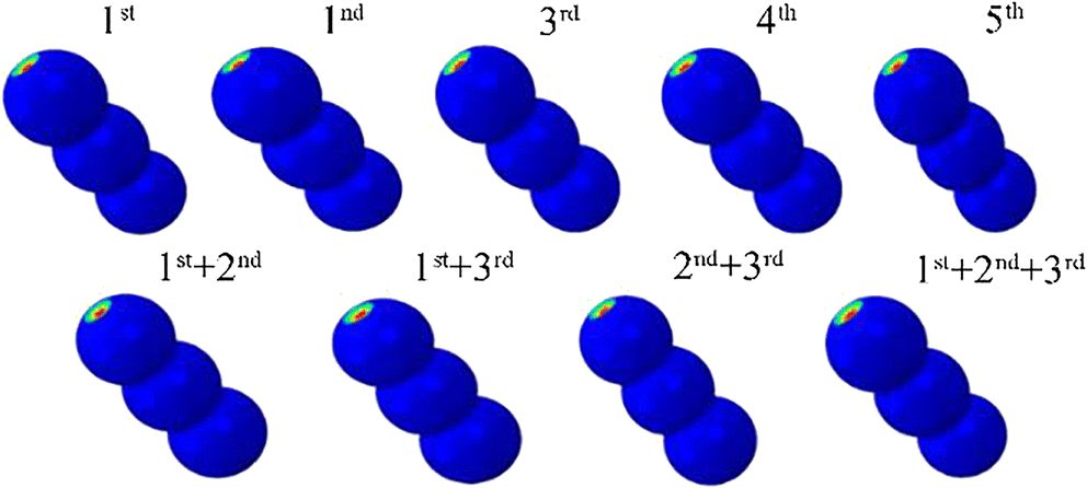 Figure 5 Post-buckling modes of the three-segment spherical shell under different imperfections
For the three types of shells, the equilibrium paths and the collapse modes were essentially the same under the five types of imperfection. Therefore, the fault path ∆ = 0.1 mm taken as an example to study the equilibrium path and nonlinear load. Figure 6 indicates that with an increase in displacement, the nonlinear load of shells initially increased and then decreased, and the maximum value of the nonlinear load was the critical point. The critical point pressures of the three-segment spherical shell, stiffened cylindrical shell, and cylindrical shell were 27.38, 4.84, and 1.43 MPa, respectively. The comparison shows that the three-segment spherical shell has the fastest downward trend, whereas two cylindrical shells had a slower downward trend. The three-segment spherical shell was more sensitive to defects than the cylindrical shells because the three-segment spherical shell acted as an extension of the spherical shell and inherited its imperfection sensitivity. The load capacity of the three-segment spherical shell was considerably larger than that of the cylindrical and ribbed cylindrical shells. Therefore, the stability of the three-segment shell was highest, which was 19.2 times that of the equivalent cylindrical shell and 5.7 times that of the cylindrical shell.
 Figure 6 Nonlinear buckling equilibrium path of the three-segment spherical and cylindrical shell with imperfections. a Cylindrical shell with and without ring rib. b Three-segment spherical shell
4 Experimentation
4.1 Experimental Analysis
To verify the results of the aforementioned computation, the three-segment spherical shell and corresponding equivalent cylindrical and stiffened cylindrical shell scale models were tested. Three scaled models were fabricated through rapid prototyping by using photosensitive resin. The main component of the resin was Future 8000 epoxy resin, which is widely used in machinery, construction, and other industries. Its material parameters are directly provided by the three-dimensional (3D) rapid prototyping company, which are as follows: Young's modulus E = 2600 MPa, Poisson's ratio, μ= 0.34, and tensile strength σb = 35 MPa. Placing a support inside during the machining process was necessary because the shell had a closed thin wall. Therefore, the inner support had to be removed at the opening to guarantee testing accuracy. The rubber was repaired at the opening to ensure that the test models were intact before test.
Additionally, the models were scanned using a 3D scanner. A manual tripod 3D scanner supplied by Open Technologies was used. The parameters used are as follows: scanning range 150 mm × 115 mm × 150 mm; pixel 200 M; and accuracy 0.02 mm. After the true contours of the test models were obtained, they were analysed using the GOM Inspect software programme for deviation inspection and evaluation. Figure 7 presents the results. The deviation of the three-segment spherical shell from perfect geometry was relatively small. The maximum deviation was mainly concentrated at around − 0.15 mm, which means the negative deviation (shown in blue colour in Figure 7) of the actual data obtained by 3D scan from perfect geometry (nominal data), which indicate that actual data lies below the nominal surface. The maximum deviation can be attributed to a lack of manufacturing accuracy. The maximum deviation of two types of cylindrical shells from the perfect geometry appeared at openings, which was caused by the presence of glue that was used for sealing. Due to the accuracy of the 3D scanner and post-processing software system, the scaled models can be regarded as perfect shells.
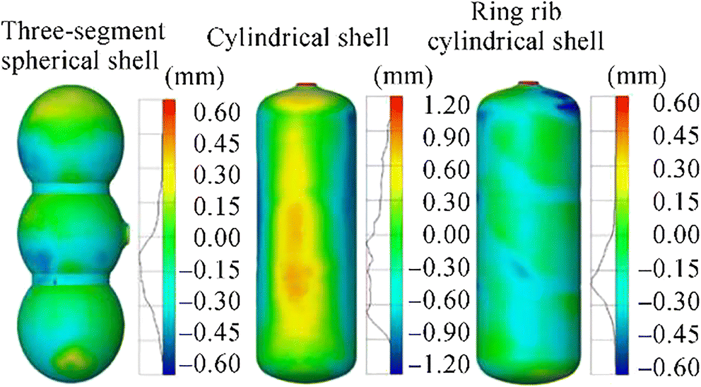 Figure 7 Deviation of local radii based on the design geometry of shells
The average thickness of three models and size of ring rib, including the length and outside diameter, were listed in Table 4. The wall thickness of each model was measured using PX-7 ultrasonic thickness gauge developed by Dakota Ultrasonics Corporation, which provided accurate measure measurements. Table 4 indicates that the wall thicknesses of the three samples were almost equal to that of a nominal shell (2 mm). The thickness distributions of the three test shells was determined using the standard deviation, and their values were near the average value, indicating that the overall thicknesses of the three test shells were similar to the numerical value.
Table 4 Geometric parameters of the three test modelsSpecies t (mm) Ring rib (mm) tmin tmax tave tstd Lr tr Cylindrical shell 1.986 1.774 1.925 0.047 N/A N/A Ring-ribbed cylindrical shell 1.954 1.782 1.871 0.038 13.908 17.996 Three-sphere shell 2.022 1.726 1.971 0.059 13.809 17.888 The test was performed to simulate the real water pressure environment by using the self-developed deep-sea pressure chamber (Figure 8). To ensure the accuracy of the test, the pressure in the cabin must be zero before the test. Each test model was immersed in a pressure chamber by using a rope bag. To sink the shells below the surface of water, a weight was tied to the rope bag of each shell. The pressure was gradually increased through manual pressurisation. When the crisp cracking sound was heard, the pressurisation was immediately stopped, and the test peak data were recorded using a pressure sensor. Their post-buckling modes were similar and acquired the form of a local dent. These results indicated a satisfactory repeatability.
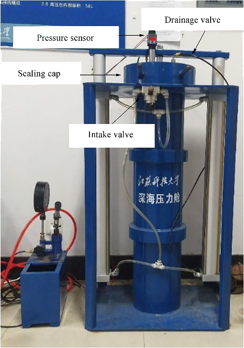 Figure 8 Photograph of the self-developed deep-sea pressure chamber
4.2 Computational Analysis
On the basis of the scan results, the comprehensive finite element models of samples were created and computed using linear bifurcation analysis and the nonlinear Riks analysis function available in Abaqus. A mesh convergence analysis was performed for each sample. The three-segment spherical, cylindrical, and stiffened cylindrical shells exhibited 24 247 S4 and 187 S3; 21 777 S4 and 246 S3; and 22 209 S4 and 272 S3 elements, respectively. Because the thicknesses of the shells were evenly distributed, the mean values for shell wall thickness were used for computations. Furthermore, the load and boundary conditions were the same as those described in Section 2.2, and uniform pressure was applied to the outer surface of each model.
The equilibrium paths of three samples are illustrated in Figure 9 and are consistent with equilibrium paths presented in Figure 6. Moreover, comparison presented in Figure 10 indicated that predicted collapse modes and experimental failure modes were similar. The local dent of the cylindrical shell occurred at the middle of the shell, and the local dent of the ring-ribbed cylindrical shell occurred at the middle of one end. However, the local dent of the three-segment spherical shell was not similar to that in the numerical result because the high sensitivity of the spherical shell towards the imperfections could lead to deviations from the local dent position.
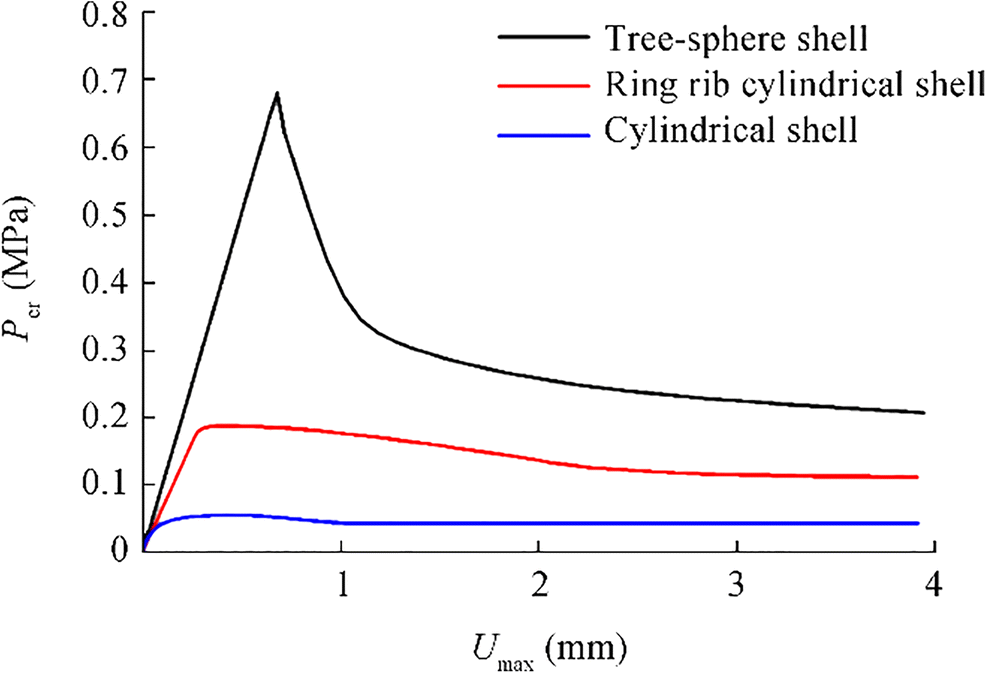 Figure 9 Nonlinear buckling equilibrium path of the three test shell models
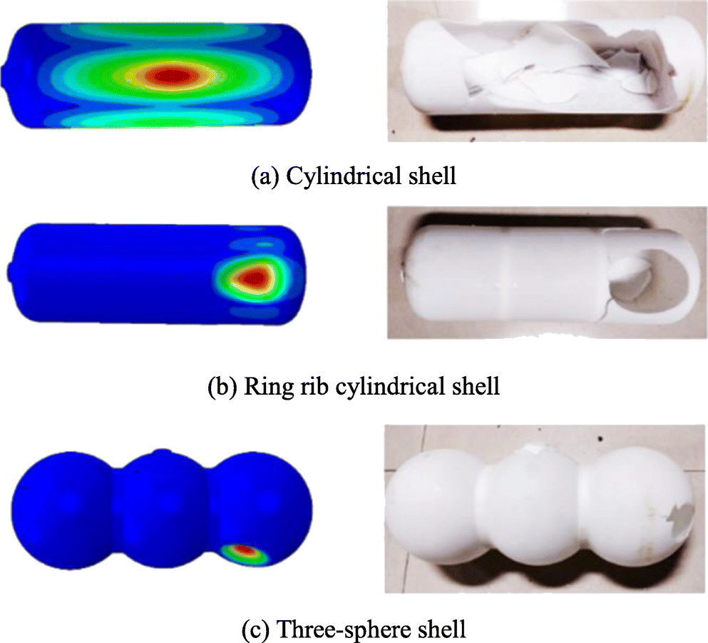 Figure 10 Numerical and experimental results for the tested shell models. a Cylindrical shell. b Ring-ribbed cylindrical shell. c Three-sphere shell
A comparison of numerical and experimental critical buckling pressure is presented in Table 5. The numerical critical buckling pressure of the cylindrical shell was 0.057 MPa, which was 0.85 times higher than the experimental collapse pressure. The numerical critical buckling pressure levels of the ring-ribbed cylindrical and three-segment spherical shells were approximately 0.98–1.04 times higher than the respective experimental failure buckling pressure levels. Notably, a bad agreement between the numerical and experimental results of cylindrical shell was obtained due to the deviation of local radii based on the design geometry of the unstiffened cylinder shell being larger than the other two shells, which is shown in Figure 7. The results indicated that the critical buckling pressure of the three-segment spherical shell considerably improved compared with that of the corresponding equivalent cylindrical shell. Future studies should focus on more precise manufacturing technologies for multiple intersecting spherical shells, such as numerically controlled machining.
Table 5 Comparison of numerical bucking pressure with experimental collapse pressureSpecies Cylindrical shell Ring-ribbed cylindrical shell Three-sphere shell Pnlb(MPa) 0.057 0.186 0.682 Ptest(MPa) 0.067 0.178 0.699 Pnlb/Ptest 0.85 1.04 0.98 5 Conclusions
In this study, the buckling performance levels of the three-segment spherical, cylindrical, and ring-ribbed cylindrical shells were investigated numerically and experimentally. The numerical results indicated that the load-carrying capacity of the three-segment spherical shell considerably improved compared with those of the cylindrical and ring-ribbed cylindrical shells. The linear and nonlinear buckling load of the three-segment spherical shell was considerably higher than that of the cylindrical and ring-ribbed cylindrical shells; therefore, the stability of the three-segment spherical shell was highest.
The experimental failure modes and buckling modes of the three types of shells showed favourable consistency in the numerical analysis. The experimental collapse modes of all shells were consistent with the numerical analysis results. The cylindrical shells collapsed in the middle of the shell; the local dent positions of the ring-ribbed cylindrical and three-spherical shells were similar; collapses were noted between the ribs and the end of the shell. The experimental results indicated that the collapse pressure of the three-spherical shell had the best superior performance, indicating that its bearing capacity is substantially higher than that of the cylindrical shell and its load-carrying capacity is approximately four times that of the ribbed cylindrical shell.
This methodology can be a valuable guideline for the predesign of shell structures. However, some limitations of this work must be noted. First, the influence about the openings of pressure shells should be considered. A multi-segment spherical shell with an opening structure can result in a more complex open-cell structure than that in a complete spherical shell opening. Exploring the influence of the position, number, and size of openings on the performance of the multi-segment spherical shell structure will be difficult in further research. Second, this study mainly investigated the initial geometric defects based on the modality. Further research on other defects such as local and axisymmetric defects is required to establish a perfect defect shell buckling mechanism.
Open Access This article is licensed under a Creative Commons Attribution 4.0 International License, which permits use, sharing, adaptation, distribution and reproduction in any medium or format, as long as you give appropriate credit to the original author(s) and the source, provide a link to the Creative Commons licence, and indicate if changes were made. The images or other third party material in this article are included in the article's Creative Commons licence, unless indicated otherwise in a credit line to the material. If material is not included in the article's Creative Commons licence and your intended use is not permitted by statutory regulation or exceeds the permitted use, you will need to obtain permission directly from the copyright holder. To view a copy of this licence, visit http://creativecommons.org/licenses/by/4.0/. -
Figure 1 Geometry of the three-segment spherical pressure hull
Figure 2 FE mesh and boundary condition of the three-segment spherical shell
Figure 3 Buckling modes of the three-segment spherical shell and two types of cylindrical shell
Figure 4 Nonlinear buckling equilibrium path of the three-segment spherical shell under different imperfections
Figure 5 Post-buckling modes of the three-segment spherical shell under different imperfections
Figure 6 Nonlinear buckling equilibrium path of the three-segment spherical and cylindrical shell with imperfections. a Cylindrical shell with and without ring rib. b Three-segment spherical shell
Figure 7 Deviation of local radii based on the design geometry of shells
Figure 8 Photograph of the self-developed deep-sea pressure chamber
Figure 9 Nonlinear buckling equilibrium path of the three test shell models
Figure 10 Numerical and experimental results for the tested shell models. a Cylindrical shell. b Ring-ribbed cylindrical shell. c Three-sphere shell
Table 1 Main parameters of three geometric models
Model L (mm) R (mm) t (mm) Dr (mm) Lr (mm) D0 n Three-sphere shell 5086 1000 20 1470 109 N/A N/A Cylindrical shell 5086 N/A 20 N/A 0 888 0 Ring-ribbed cylindrical shell 5086 N/A 20 N/A 109 898 2 Table 2 Critical buckling loads and circumferential waves of the three-segment spherical and cylindrical shells
Buckling eigenmode Plb (MPa) (Circumferential waves number) Three-segment spherical shell Cylindrical shell Ring-ribbed cylindrical shell 1st 52.42 (9) 5.60 (3) 18.17 (4) 2nd 52.42 (9) 5.60 (3) 18.17 (4) 3rd 52.45 (9) 8.37 (2) 19.36 (4) 4th 52.45 (9) 8.37 (2) 19.36 (4) 5th 52.45 (9) 9.17 (4) 19.62 (5) Table 3 Critical buckling load of the three-segment spherical shell with imperfections under different eigenmode shapes
Buckling eigenmode Critical buckling load(MPa) 1st 17.09 2nd 17.63 3rd 17.14 4th 17.92 5th 17.17 1st + 2nd 14.54 1st + 3rd 13.85 2nd + 3rd 15.56 1st + 2nd + 3rd 13.54 Table 4 Geometric parameters of the three test models
Species t (mm) Ring rib (mm) tmin tmax tave tstd Lr tr Cylindrical shell 1.986 1.774 1.925 0.047 N/A N/A Ring-ribbed cylindrical shell 1.954 1.782 1.871 0.038 13.908 17.996 Three-sphere shell 2.022 1.726 1.971 0.059 13.809 17.888 Table 5 Comparison of numerical bucking pressure with experimental collapse pressure
Species Cylindrical shell Ring-ribbed cylindrical shell Three-sphere shell Pnlb(MPa) 0.057 0.186 0.682 Ptest(MPa) 0.067 0.178 0.699 Pnlb/Ptest 0.85 1.04 0.98 -
Arbocz J, Starnes JH (2002) Future directions and challenges in shell stability analysis. Thin-Walled Struct 40(9): 729–754. https://doi.org/10.1016/S0263-8231(02)00024-1 Błachut J (2014) Experimental perspective on the buckling of pressure vessel components. Appl Mech Rev 66(1): 010803. https://doi.org/10.1115/1.4026067 Błachut J, Jaiswal OR (2000) On buckling of toroidal shells under external pressure. Comput Struct 77(3): 233–251. https://doi.org/10.1016/S0045-7949(99)00226-6 Błachut J, Magnucki K (2008) Strength, stability, and optimization of pressure vessels: review of selected problems. Appl Mech Rev 61(6): 060801. https://doi.org/10.1115/1.2978080 Błachut J, Smith P (2008) Buckling of multi-segment underwater pressure hull. Ocean Eng 35(2): 247–260. https://doi.org/10.1016/j.oceaneng.2007.08.003 Castro SGP, Zimmermann R, Arbelo MA, Khakimova R, Hilburger MW, Degenhardt R (2014) Geometric imperfections and lower-bound methods used to calculate knock-down factors for axially copressed composite cylindrical shells. Thin-Walled Struct 74: 118–132. https://doi.org/10.1016/j.tws.2013.08.011 Charles Garland B (1968) Design and fabrication of deep-diving submersible pressure hulls. SNAME Trans 76: 161–179 China Classification Society (CCS) (2013) Rules for the classification and construction of diving systems and submersibles Eurocode CEN (2007) 3–design of steel structures – part 1–6: strength and stability of shell structures. Brussels Eur Comm Stand Gou P, Cui WC (2009) Structural optimization of multiple intersecting spherical pressure hulls based on Kriging model. J Sh Mech 13(1): 100–106 (in Chinese) Hall J, Leon G, Kelly J (1991) Deep submergence design of intersecting composite spheres. In composites-design, manufacture and applications, SAMPE. 2F1-2F12 Jasion P, Magnucki K (2015) Elastic buckling of Cassini ovaloidal shells under external pressure - theoretical study. Arch Mech 67(2): 179–192. https://doi.org/10.24423/aom.1818 Leon G (1971) Intersecting titanium spheres for deep submersibles. J Eng Mech Div 97(3): 981–1006 https://doi.org/10.1061/JMCEA3.0001430 Liang XX (2006) Study on special problem of submarine pressure hull. Ph. D. thesis, Harbin Engineering University, Harbin Liang CC, Shiah SW, Jen CY, Chen HW (2004) Optimum design of multiple intersecting spheres deep-submerged pressure hull. Ocean Eng 31(2): 177–199. https://doi.org/10.1016/S0029-8018(03)00120-3 Ness CC, Simpson WM Jr (2009) A new submarine paradigm. Nav Eng J 112(4): 143–152. https://doi.org/10.1111/j.1559-3584.2000.tb03325.x Pan BB, Cui WC (2010) An overview of buckling and ultimate strength of spherical pressure hull under external pressure. Mar Struct 23(3): 227–240. https://doi.org/10.1016/j.marstruc.2010.07.005 Pan BB, Cui WC (2011) A comparison of different rules for the spherical pressure hull of deep manned submersibles. J Sh Mech 15(3): 276–285. https://doi.org/10.3969/j.issn.1007-7294.2011.03.009 Ross CTF (2006) A conceptual design of an underwater vehicle. Ocean Eng 33(16): 2087–2104. https://doi.org/10.1016/j.oceaneng.2005.11.005 Ross CTF, Terry A, Little APF (2001) A design chart for the plastic collapse of corrugated cylinders under external pressure. Ocean Eng 28(3): 263–277. https://doi.org/10.1016/S0029-8018(00)00007-X Stanley IW (2012) Department of precision and microsystems engineering on lightweight design of submarine pressure hull. PhD thesis, Delft University Technology, Holland Zhang M, Tang WX, Wang F, Zhang J, Cui WC, Chen Y (2017) Buckling of bi-segment spherical shells under hydrostatic external pressure. Thin-Walled Struct 120:1–8. https://doi.org/10.1016/j.tws.2017.08.017 Zhang J, Zuo XL, Wang WB, Tang WX, Li HY (2018) Design and buckling analysis of double-segment egg-shaped pressure hulls. J Sh Mech 22(11): 1396–1406(in Chinese). https://doi.org/10.3969/j.issn.1007-7294.2018.11.009 Zingoni A (2015) Liquid-containment shells of revolution: a review of recent studies on strength, stability and dynamics. Thin-Walled Struct 87:102–114. https://doi.org/10.1016/j.tws.2014.10.016 Zuo XL, Wang WB, Tang WX, Tang W (2014) Overviews of investigation on submersible pressure hulls. Adv Nat Sci 7(4): 54–61. https://doi.org/10.3968/6129
| Citation: |
Jian Zhang, Shengqiu Li, Weicheng Cui, Kai Xiang, Fang Wang, Wenxian Tang (2020). Buckling of Multiple Intersecting Spherical Shells. Journal of Marine Science and Application, 19(4): 634-641. https://doi.org/10.1007/s11804-020-00168-w

|