Study on Ultimate Compressive Strength of Aluminium-Alloy Plates and Stiffened Panels
https://doi.org/10.1007/s11804-020-00170-2
-
Abstract
This work reviews the ultimate compressive strength of aluminium plates and stiffened panels. The effect of boundary condition, initial imperfection, welding-induced residual stress and heat-affected zone are discussed. As the effect of manufacturing technology lacks in the literature, this effect is analysed employing the finite element method, considering the technology of welding and integrated extrusion. The numerical analyses have shown that the ultimate strength of the integrated extruded stiffened panel is relatively higher than the one of the traditional welded panel.-
Keywords:
- Ultimate strength ·
- Compressive load ·
- Stiffened panel ·
- Aluminium alloy ·
- Review
Article Highlights• Ultimate compressive strength of aluminium plates and stiffened panels are reviewed.• The effect of boundary condition, initial imperfection, welding-induced residual stress and heat-affected zone are discussed.• The effect of manufacturing technology is analysed. -
1 Introduction
Stiffened panels are the main structural components in ship hull girders. The buckling failure of deck or bottom stiffened panels may lead to the overall collapse of ships. Unlike columns which buckling implies the collapse, plates and stiffened panels can sustain further loads after the buckling occurs locally in the elastic or even inelastic regime. The design and strength assessment of plates and stiffened panels are moving towards the ultimate limit states in recent decades, as is required by the new reliability-based design formulations (Guedes Soares et al. 1996).
Nowadays, aluminium alloys are widely used in building hulls and superstructures of high-speed vessels instead of steels due to their high strength and lower weight (Aalberg et al. 2001; Kasten 2016; Liu et al. 2019). In aluminium stiffened plates, fabricated by fusion welding, the material softening takes place in the heat-affected zone (HAZ) along the weld seam. In contrast to the steel stiffened panel, the yield stress in the HAZ of the welded aluminium panel is reduced significantly as compared with the base material. Hence, this leads to the reduction of the compressive ultimate strength of aluminium panels. The tensile residual stresses exist in the HAZ, which are self-equilibrated by the corresponding compressive stresses in the adjacent zones. The welding-induced residual stresses are recognized to decrease the ultimate bearing capacity of both aluminium and steel panels, but in different way. Therefore, despite the existing reviews of the of the ultimate strength of steel plates and stiffened panels subjected to axial compressive load (Guedes Soares and Soreide 1983; Zhang 2015), there is a need of dealing in a systematic way with the results specific to aluminium-alloy plates.
The focus here is on the aluminium-alloy plates and stiffened panels, reviewing many studies performed by employing different approaches. Analytical formulations are proposed based on the first principles and hypotheses of structural mechanics. They are of considerable value and very useful for the ultimate limit state design and reliability assessment. Empirical formulations are proposed based on a regression analysis of experimental test data and numerical results. They differ from the analytical approaches since they include failure observations. To clearly understand the complexity of material and structural behaviour up to collapse, the experimental tests become an inevitable part of the ultimate strength assessments or at least in developing and validating the analytical, empirical and numerical methods. Due to the limitation of testing facilities, scaled models are used instead of full-scale prototypes. With the rapid development of computational technology, numerical methods are considered as the most powerful tools for analysing the nonlinear behaviour of the structural system. The nonlinear finite element method (NLFEM) has been widely employed to analyse the behaviour and ultimate strength of plates and stiffened panels.
This paper reviews the ultimate compressive strength of aluminium plates and stiffened panels comprehensively performed by different methods. The effects of the initial deflections, welding-induced residual stresses and strength deterioration in the HAZ are also summarized. Moreover, the influence of the manufacturing technology on the ultimate compressive strength of aluminium-alloy stiffened panels is investigated by performing a series of finite element analyses. The numerical analyses of the strength of aluminium structures are compared and discussed, and some future research works are recommended.
2 Review on Ultimate Strength of Aluminium Plates
2.1 Buckling Failure Pattern
The deck and bottom structures of ships are subjected periodically to compressive and tensile loads resulting from the sagging and hogging vertical bending moments. In this case, the plating between longitudinal stiffeners and transverse frames is compressed, and thus in most current practical design materials, it is assumed to be simply supported or clamped at four edges subjected to an axial load (Wang et al. 2005; Yao and Fujikubo 2016; Paik 2018). At the initial regime of loading, the compressive stress and lateral deflection increase linearly. When the compressive stress reaches the critical value, the plate buckles with large lateral deflections and the in-plane stiffness of the plate reduces significantly. The buckling failure of the plate may be categorized into elastic, elastic-plastic and plastic buckling. The first type of buckling occurs typically in the elastic regime for the thin plates, while the others often occur in the inelastic regime for thick plates after the plastic deformation takes place locally or the plate yields over large regions. The yielding initiates at the longitudinal edges and spreads to the surrounding areas.
2.2 Experimental Test
It is seen that the experimental data are valuable to verify the results based on analytical or empirical methods and collected data will provide a better understanding of the behaviour of the structures. Unfortunately, experimental results of aluminium plates under compression are rare and not widely open. The experimental tests carried by Mofflin (1983) are the most useful, as described thoroughly by Collette (2005). The results of this study have provided an excellent database for many comparative studies of high-speed aluminium vessels (Collette et al. 2008; Benson et al. 2011).
Conley et al. (1963) studied the buckling and ultimate compressive strength for various types of steel and aluminium plates. The buckling load was considered to be the load where the strain curve reverses slope or has the inflexion point. In comparison with the theoretical results, calculated from the proposed formulation, the testing results showed a good agreement in some cases, and some discrepancies were found due to the difficulty to fulfil all conditions during testing. Based on the obtained ultimate compressive loads, a new design curve that shows the relationship between strength factor and slenderness ratio was recommended.
Mofflin (1983) tested the ultimate compressive strength of aluminium alloys plates, likely to be encountered in marine structures, considering the effect of initial deflection and welding. The longitudinal edges were supported by a special mechanism to restrain the lateral deflection and freely rotate, while the transverse edges were clamped partially. The material properties were measured by tension and compression tests. The heat was added to the longitudinal edges and at the mid-length of the plate to simulate the effect of welding and initial deflection. Two levels of initial deflections were analysed. The ultimate strength and stress-strain curves were obtained to validate other methods.
Seifi and Khoda-yari (2011) investigated buckling loads of the cracked aluminium plates to evaluate the effect of the crack. Three boundary configurations, simply supported, clamped and partially clamped, were employed using suitable upper and lower fixtures. The plates with clamped edges exhibited a higher compressive capacity and are more stable.
2.3 Analytical and Empirical Methods
For evaluating the ultimate compressive strength of aluminium plates rapidly, several formulations are developed like one of Johnson-Ostenfeld, Faulkner (1975), Kristensen (2001), Paik and Duran (2004), Wang et al. (2005) and Eurocode 9 (2009).
Initially, the critical buckling strength of aluminium plates may be estimated based on the Johnson-Ostenfeld formulation which is well summarized in Paik et al. (2005b), Paik (2018) and Syrigou and Dow (2018). It is given as follows:
$$ {\sigma}_{\mathrm{cr}}=\left\{\begin{array}{l}{\sigma}_E\\ {}{\sigma}_{F\left[1-{\sigma}_F/(4){\sigma}_E\right]}\end{array}\right.\kern0.5em {\displaystyle \begin{array}{c}\mathrm{when}\kern0.5em {\sigma}_E\le {\alpha \sigma}_F\\ {}\mathrm{when}\kern0.5em {\sigma}_E\le {\alpha \sigma}_F\end{array}} $$ (1) where σE is the elastic buckling stress (Eq. (2)), σF is the reference yield stress: σF = σY for the compressive normal stress and $ {\sigma}_{\mathrm{F}}={\tau}_{\mathrm{Y}}={\sigma}_{\mathrm{Y}}/\sqrt{3} $ for the shear stress, σY is the material yield stress and α is a constant depending on the material proportional limit, which is usually taken as α = 0.5 or 0.6.
The elastic buckling stress is given as follows:
$$ {\sigma}_{\mathrm{E}}\frac{k{\pi}^2E}{12\left(1-{v}^2\right)}{\left(\frac{t}{b}\right)}^2 $$ (2) where k is the buckling coefficient specified based on the corresponding load, E is Young's modulus, ν is the Poisson's ratio, t is the plate thickness and b is the stiffener spacing.
The empirical formulation, as proposed by Faulkner (1975), predicts the ultimate strength of steel plates under axial compression, and it is perhaps the most commonly used in the marine industry. This formulation is also used for aluminium plates where the equivalent yield stress is used, considering the effect of HAZ:
$$ \frac{\sigma_{\mathrm{ux}}}{\sigma_{\mathrm{Yeq}}}=\frac{2}{\beta }-\frac{2}{\beta^2} $$ (3) where $ \beta =\left(b/t\right)\sqrt{\sigma_{\mathrm{Yeq}}/E} $ is the plate slenderness ratio; b, t and E are mentioned above; and σYeq is the equivalent yield stress:
$$ {\sigma}_{\mathrm{Y}\mathrm{eq}}=\frac{2\left[{ab}_{\mathrm{haz}}+\left(b-2{b}_{\mathrm{haz}}\right){b}_{\mathrm{haz}}\right]{\sigma}_{\mathrm{Y}\mathrm{haz}}+\left(a-2{b}_{\mathrm{haz}}\right)\left(b-2{b}_{\mathrm{haz}}\right){\sigma}_{\mathrm{Y}}}{ab}, $$ where a is the plate length, bhaz the width of HAZ and σYhaz the yield stress in the HAZ.
Kristensen (2001) proposed a formulation for the welded plate under axial compression, with 25-mm width of HAZ and yield stress in the HAZ equal to 50% of the base material yield stress; it is given as follows:
$$ \frac{\sigma_{\mathrm{mux}}}{\sigma_{\mathrm{elpl}}}=0.7495-0.7036\exp \left(-3.387{\beta}^{-1.224}\right) $$ (4) where σmux is the mean uniaxial ultimate longitudinal stress; $ {\sigma}_{\mathrm{elpl}}={\sigma}_{0.2}^{\frac{n}{n-1}}.{(0.002E)}^{\frac{n}{n-1}} $ is the stress that corresponds to equal elastic and plastic strain, $ n=\frac{1\mathrm{n}2}{1\mathrm{n}\left(\frac{\sigma_{0.2}}{\sigma_{0.1}}\right)} $; and σ0.1 and σ0.2 are the stress corresponding to a residual strain equal to 0.1% and 0.2%, respectively.
Paik and Duran (2004) proposed a closed-form empirical formulation (Eq. (5)) to estimate the ultimate compressive strength of aluminium plates simply supported at four edges based on a regression analysis of numerical results. The average level of the initial deflections is considered, while the residual stresses were ignored. The effect of softening in the HAZ is also taken into account, where the yield stress in the HAZ was assumed to equal 70% of the base material yield stress.
$$ \frac{\sigma_{\mathrm{ux}}}{\sigma_{{\mathrm{Y}}_{\mathrm{eq}}}}=\left\{\begin{array}{lll}1.0& \mathrm{for}& \beta \le 0.46\\ {}-0.215\beta +1.1& \mathrm{for}& 0.46\kern0.5em \lt \kern0.5em \beta \le 2.2\\ {}-0.083\beta +0.81& \mathrm{for}& \beta \gt 2.2\end{array}\right. $$ (5) The modified Faulkner's formulation (Eq. (3)) was extended by Wang et al. (2005), where the reduction factor ψ was used to the definition of β. The proposed formulation was validated by comparing with the nonlinear finite element results from 132 plating models covering a range of β from 1 to 4. The strength deterioration in the HAZ and the initial deflections were considered; however, the residual stresses were ignored.
$$ \frac{\sigma_{\mathrm{ux}}}{\sigma_{\mathrm{Y}}}\left\{\begin{array}{c}1.0\\ {}\frac{2}{\overline{\beta}}-\frac{1}{{\overline{\beta}}^2}\end{array}\right.{\displaystyle \begin{array}{c} for\kern0.2em \overline{\beta}\le 1\\ {} for\kern0.2em \overline{\beta} \gt 1\end{array}} $$ (6) where $ \overline{\beta}=\frac{1}{\psi}\frac{b}{t}\sqrt{\frac{\sigma_Y}{E}} $, ψ = 1 for σYhaz/σY ≥ 1 − 0.1β0.5, $ \psi =1.142-\frac{1.42}{\beta^{0.5}}\left(1-{\sigma}_{\mathrm{Y}\mathrm{haz}}/{\sigma}_{\mathrm{Y}}\right)\kern0.24em \mathrm{for}\kern0.24em {\sigma}_{\mathrm{Y}\mathrm{haz}}/{\sigma}_{\mathrm{Y}} \lt 1-0.1{\beta}^{0.5} $ and $ \beta =\frac{b}{t}\sqrt{\frac{\sigma_Y}{E}} $.
Based on Faulkner's formulation, the European Committee for Standardization (CEN) proposed an empirical formulation to calculate the local buckling compressive resistance of aluminium plates, considering the material softening in the HAZ (Eurocode 9 2009). According to Eurocode 9 class 4, the design value of the compressive force NEd should satisfy:
$$ \frac{N_{Ed}}{N_{Rd}}\le 1.0 $$ (7) $$ {N}_{Rd}=\min \left({N}_{o, Rd};{N}_{u, Rd}\right) $$ (8) where NRd is the design resistance; No, Rd = Aeffσo/γM1 for the overall yielding and local buckling and Nu, Rd = Anetσo/γM2 for the local failure; Aeff, Anet is the effective area of the cross-section and the area of the least favourable cross-section taking into account the HAZ softening, respectively; σo, σu is the yield strength and ultimate tensile strength; and γM1, γM2 is the partial factor for the resistance of members concerning instability, and in the case of the cross-sections subjected to tensile load to fracture, respectively, γM1 = 1.1 and γM2 = 1.25 are recommended.
Benson et al. (2011) performed a comparative study based on the relevant data from the experimental investigation of aluminium plates under uniaxial compression, as presented in Collette (2005), using Eqs. (3), (5), (7) and (8). The authors realized that the obtained results show a reasonable correlation with the test data. About 10% difference between three approaches can be found, and where the Faulkner formulation shows the upper limit at the lower and moderate slenderness, the Eurocode formulation shows the lower limit at the higher slenderness, and the formulation proposed by Paik and Duran (2004) provides a lower prediction for stocky plates.
2.4 Numerical Methods
With the rapid development of the informatics technology, especially recent two decades, many investigations have been performed on the nonlinear finite element models to simulate the buckling and ultimate strength of aluminium plates under axial compression. It is recognized that to improve the accuracy in predicting the behaviour and ultimate capacity of plates, many parameters need to be taken into account in the analysis, including aspect ratio, slenderness, material properties of alloys, initial imperfections, welding-induced residual stresses, HAZ and loading.
Collette et al. (2008) performed a series of finite element simulations of the experimental data of Mofflin (1983). The material properties, initial imperfections and boundary conditions were considered.
Seifi and Khoda-yari (2011) carried out numerical investigations on the buckling of thin aluminium-cracked plates and validated against experimental results. The parametric study is performed selecting the plate dimensions (length, breadth and thickness), crack length and its orientation as the variables. Three types of boundary conditions were used, including clamped-clamped, simple-clamped and simple-simple conditions. The maximum discrepancy is 10% between numerical and experimental results.
Benson et al. (2011) examined the ultimate strength of aluminium plates, considering the effects of almost related parameters. Both initial imperfections and welding-induced residual stress were introduced. All plates were assumed to be simply supported at four edges. The results show good agreement with Eurocode' s formulation. The study was extended by Benson et al. (2013b). A parametric dataset of load-shortening curves accounting for the axial compressive load was derived in assessing the ultimate global strength of aluminium hull girder using the progressive collapse method.
Syrigou and Dow (2018) investigated the ultimate strength of aluminium-alloy plates with a wide range of the slenderness ratio under different loading conditions, considering the initial geometric imperfections, welding-induced residual stresses and HAZ. The results were compared with various analytical formulations. A good correlation was obtained for the unrestrained plates and stocky constrained plates (β < 2), while the ultimate compressive strength of the slender-constrained plates (β > 2) is higher than the ones estimated by various analytical formulations.
3 Review on Ultimate Strength of Aluminium Stiffened Panels
3.1 Buckling Failure Pattern
As the applied load reaches its critical value, the stiffened panel buckles locally or as a unit (overall buckling). The local buckling of the panel involves the buckling of plating or stiffeners. The overall buckling occurs when the stiffness of the stiffeners is relatively small, while for relatively substantial stiffeners, the plating between stiffeners buckles. The local buckling of stiffeners is often exhibited in the stiffener web or the sideway distortion.
A stiffened panel can be subjected to further loading up to the collapse even after the occurrence of the local buckling. The buckling and/or yielding are initially present in the plate and then are spread towards the stiffeners. Eventually, at the ultimate limit state, the plates and stiffeners undergo the excessive buckling and yielding.
3.2 Experimental Results
Numerous mechanical experiments were carried out to investigate the structural behaviour, collapse mode and ultimate load-carrying capacity of aluminium stiffened panels. One of the earliest experiments on the aluminium panels was performed by Aalberg et al. (2001), where the panels were fabricated with two types of extruded profiles (open- and closed-section stiffeners). The extruded profiles were welded by MIG (melt inert gas) and FSW (friction stir weld) methods in the longitudinal direction. Special mechanisms, bearing rail and bearing pad, were designed in the test rig to create the simply supported boundary conditions at the loaded edges and to eliminate the effect of the end connections (Figure 1a). The position of the bearings was selected to ensure the transfer of the thrust through the neutral axis of the panel cross-sectional area. Two collapse modes were observed during testing: overall flexural buckling and collapse initiated from the tripping of the stiffeners (Figure 1b).
 Figure 1 Collapse test of stiffened panel (Aalberg et al. 2001)
Similar collapse tests were also carried out experimentally and numerically by Zha and Moan (2001, 2003), where the torsional failure mode of the stiffeners was predominant. The significant torsion of stiffeners was observed when the applied load reached about 60%–70% of the ultimate load. In addition, the initial imperfections affect the collapse modes of stiffeners.
To derive accurate results, full-scale prototype specimens are preferred. Hence, a series of collapse tests under uniaxial compression were carried out by Paik et al. (2008) presenting results of collapse tests of full-scale prototype models. These specimens were built from plating and flat bar or tee bar or extruded tee bar as single and multi-bay stiffened panels. The simply supported boundary condition was used at the loaded edges, while two types of boundary conditions were considered for the unloaded edges, namely, simply supported and free ones. Different collapse modes were observed from the tests depending on the panel geometries. The lateral-torsional buckling mode occurred for panels with significant web height, and the beam-column mode was seen at panels with smaller web height. It was found that the ultimate strength of the one-bay panel is slightly smaller than the one of the three-bay panels.
Rønning et al. (2010) carried out the ultimate strength of transversely stiffened aluminium panels subjected to in-plane compressive load (Figure 2). Both MIG and FSW welding methods were used for welding the extrusions. The initial deformations were measured, excluding the residual stresses. The tests were carried out by controlling the end-shortening displacement, and the load, in-plane displacement, stiffener strain and distortion were recorded continuously during testing. The results showed that the panels collapsed in two different deformation modes, local buckling of the plate between the stiffeners and global flexural buckling.
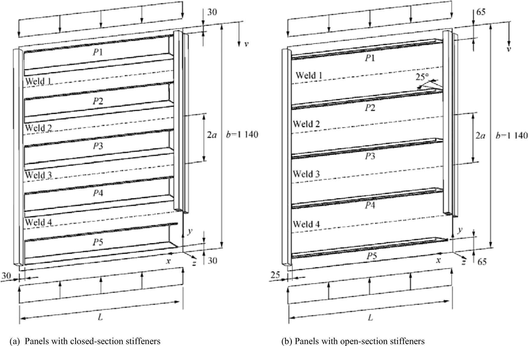 Figure 2 Transversely stiffened aluminium panel tested by Rønning et al. (2010)
The buckling collapse testing of the friction stir welded aluminium stiffened plates under axial compression was introduced by Paik et al. (2012). The object of the test structure was a full-scale deck structure of a high-speed vessel. The sequence of welding for the fabrication of the specimens in these two testing series was carefully controlled, and six types of welding-induced initial imperfections were measured. Based on the statistical analyses, three levels of welding-induced initial deflections, initial residual stresses and breadth of the HAZ were proposed. Cylindrical bearing mechanisms were used to provide the simply supported boundary conditions, similar to Aalberg et al. (2001). It was observed that the column-type collapse mode was dominant. The experimental results were compared with the numerical results with/without considering the effect of HAZ and welding-induced residual stresses. Afterwards, both numerical and experimental results were used to validate the empirical formulation proposed by Paik (2007b), achieving a good agreement.
In general, the experiments provide a good understanding of the behaviour and collapse mechanism of aluminium structures, especially to investigate the new structural configurations and the combined loading conditions, etc.
3.3 Finite Element Analysis
The refined numerical codes are powerful tools to solve the nonlinearities of the structural systems and to analyse complicated structures. This method is typically used to assess the strength of the structures that are designed by analytical or empirical methods and for the initial design to find the optimal structural design solution. However, the calculation accuracy is highly dependent on the skill of the analysts. In the last two decades, this method is increasingly used in the ultimate strength assessment of aluminium plates and stiffened panels. Table 1 shows various numerical codes for the ultimate strength analysis of plates and stiffened panels. Figure 3 shows an example of a numerical simulation.
Table 1 Numerical codes and their application (ISSC 2018)Numerical code Organization Component applicability ABAQUS Abaqus Inc. Stiffened/unstiffened panel ALPS/ULSAP Pusan National University Stiffened/unstiffened panel ANSYS Ansys Inc. Stiffened/unstiffened panel BV Adv. Buckling Bureau Veritas Stiffened panel DNV/PULS DNV-GL Stiffened/unstiffened panel MSC/MARC MSC Stiffened/unstiffened panel  Figure 3 Distortions and stress distributions at ultimate limit state (Khedmati et al. 2009)
Zha and Moan (2001, 2003) performed numerical simulations to analyse the collapse behaviour and ultimate strength of aluminium stiffened panels. The influence of HAZ, initial deflections and welding-induced residual stresses was considered. The width of the HAZ was chosen to equal either 12.5 or 25 mm for both longitudinal and transverse welds. The shell element was used to model the panels, and the mesh convergence test was conducted to find the suitable mesh size for evaluating precisely the behaviour of the HAZ. The Ramberg-Osgood relationship was employed to model the stress-strain curve of the material, where the related parameters were received from the material tensile test. The HAZ leads to about 15% strength reduction of the ultimate load, but the effect of the residual stresses is not significant.
The structural behaviour and ultimate strength of aluminium panels are very sensitive to the welding types, plate thickness, HAZ width, initial deflections, residual stress and material properties. Thus, sensitivity analyses of these influential parameters were performed by Rigo et al. (2003), Khedmati et al. (2009, 2012) and Paulo et al. (2013) by various finite element analyses. Three-span FE model was used with a restrained rotation at two loaded edges and simply supported along two longitudinal edges. The initial deflection shape of a thin-horse mode was defined by a linear static analysis where a uniform lateral pressure applied to the panel. The width of the HAZ was considered to extend 25 mm at each side of the weld and 25 mm in the stiffener web. The results showed that the plastic buckling analyses are susceptible to these influence factors.
Several numerical investigations have been performed to simulate the experimental tests and/or to derive the database for regression analyses to establish different empirical formulations (Paik 2007a, 2007b; Paik et al. 2008, 2012; Khedmati et al. 2010b, 2014).
Khedmati and Ghavami (2009) analysed the buckling and ultimate strength behaviour of stiffened aluminium panels with fixed or floating transverse frames. The results indicated that the ultimate strength of panels is affected by the position of the floating transverse frames. Moreover, the profile and the type of connection of the transverse frames might influence the buckling strength. Li et al. (2017) also performed FE analyses of stiffened panels with fixed or floating transverse frames. In their analyses, the welding-induced residual stresses and HAZ were investigated. The existence of mechanical imperfections has a significant effect on the ultimate strength of the aluminium stiffened panels. Interestingly, the residual stresses might have a positive effect.
The ultimate strength of panels fabricated from extruded aluminium profiles subjected to axial compression was investigated by Paulo et al. (2013) and Li et al. (2018) using the test panels of Aalberg et al. (2001). The initial imperfections were simulated, and the numerical results were compared with the experimental response curves. The sensitivity analyses on the initial imperfections, material properties and geometric parameters were performed. The results show the same conclusions as Li et al. (2017). Various cross-sections formed of extruded profiles (T-shaped, tubular and trapezoidal) were designed and analysed by Ren et al. (2018), proposing the most suitable configuration of aluminium extrusion for the upper deck structure of a warship.
The ultimate compressive strength of the equivalent aluminium and steel stiffened panels was investigated by Doan et al. (2020). The equivalent geometry relationships were proposed based on the Classification Society Rules (Lloyd's Register 2019a). The results proved that the proposed formulations are suitable for designing the equivalent panels.
3.4 Empirical and Analytical Methods
Due to the complexity of the structures and the effect of various uncertainties, few analytical formulations were developed, and almost empirical formulations were proposed based on the regression analyses of the numerical results. Recently, Kim et al. (2018) thoroughly reviewed the existing empirical formulations for predicting the ultimate strength of stiffened panels subjected to uniaxial compression where the well-known design formulations proposed by Johnson-Ostenfeld and Perry-Robertson can be applied for both steel and aluminium materials.
Paik and Duran (2004) performed the finite element analyses on fifty conventional stiffened panels with plate slenderness ratio, β, in the range of 1.44 to 3.41 and column slenderness ratio, λ, of 0.23 to 2.24. The 25-mm width of HAZ was assumed along the welding lines, and the initial imperfections of plate and stiffener were considered; however, the residual stresses were excluded. Based on the obtained results, an empirical formulation was developed:
$$ {\displaystyle \begin{array}{c}{\sigma}_{u\frac{\sigma_{Yeq}}{\sqrt{1.038+1.099{\lambda}^2+0.093{\beta}^2-0.047{\lambda}^2{\beta}^2+1.648{\lambda}^4}}}\\ {}{\sigma}_u\le {\sigma}_{Yeq}/{\lambda}^2\end{array}} $$ (9) where σYeq represents the equivalent yield stress; $ \beta =\frac{b}{t}=\sqrt{\frac{\sigma_{Yeq}}{E}} $ and $ \lambda =\frac{a}{\pi r}\sqrt{\frac{\sigma_{\mathrm{Yeq}}}{E}} $ denote the plate and stiffener slenderness ratio, respectively; a, b and t are the length, breadth and thickness of the plate; and r is the gyration radius.
Adapting the Johnson-Ostenfeld relation, Wang et al. (2005) introduced a formulation to calculate the critical buckling stress of the longitudinals in compression:
$$ {\sigma}_{\mathrm{cr}}=\left\{\begin{array}{c}{\sigma}_{\mathrm{E}}\\ {}{\sigma}_{\mathrm{Y}}\left[1-{\sigma}_{\mathrm{Y}}/\left(4{\sigma}_{\mathrm{E}}\right)\right]\end{array}\begin{array}{c}\mathrm{when}\;{\sigma}_{\mathrm{E}}\le 0.5{\sigma}_{\mathrm{Y}}\ \;\; {}\mathrm{when}\;{\sigma}_{\mathrm{E}}\le 0.5{\sigma}_{\mathrm{Y}}\end{array}\right. $$ (10) Eurocode 9 (2009) considers a panel as a combination of individual members (plating, strut, column), and the entire panel should be checked to satisfy all requirements of all members. For a panel under axial compression, the design value of the compression force NEd (see Eq. (7)), local buckling resistance Nu, Rd (yield check Eq. (11)) and design axial resistance Nc, Rd (column check Eq. (12)) should be checked.
$$ {N}_{\mathrm{u},\mathrm{Rd}}={A}_{\mathrm{net}}{\sigma}_{\mathrm{u}}/{\gamma}_{\mathrm{M}2} $$ (11) $$ {N}_{\mathrm{c},\mathrm{Rd}}={A}_{\mathrm{eff}}{\chi \sigma}_o/{\gamma}_{\mathrm{M}1} $$ (12) where χ is the reduction factor for the flexural buckling.
When the stiffeners are significantly numerous and small, the stiffeners deflect together with the plating, and the panel may buckle in the overall grillage buckling mode under compressive loads. In this case, the stiffeners are assumed to be smeared into the plating, and the stiffened panel may be idealized as an equivalent orthotropic plate. Its elastic properties are different in the two orthogonal directions. Adapting orthotropic plate theory, the compressive buckling load for a simply supported orthotropic plate was given for aluminium material in Eurocode 9 (2009) (see Eqs. (13) and (14)). Using the same approach, Benson et al. (2013c, 2015) calculated the panel stress-strain curves considering both interframe and overall buckling modes. A series of case studies were tested and compared with the nonlinear FE analysis results. A good agreement proved that this method could be applied in the calculation of ultimate longitudinal strength of the hull girder of the lightweight ship employing the progressive collapse method.
$$ {N}_{\mathrm{cr}}=\frac{\pi^2}{b}\left[\frac{B_{\mathrm{x}}}{{\left(L/b\right)}^2}+2H+{B}_{\mathrm{y}}{\left(L/b\right)}^2\right]\kern0.36em \mathrm{if}\kern0.24em \frac{L}{b} \lt \sqrt[4]{\frac{B_{\mathrm{x}}}{B_{\mathrm{y}}}} $$ (13) $$ {N}_{\mathrm{cr}}=\frac{2{\pi}^2}{b}\left[\sqrt{B_{\mathrm{x}}{B}_{\mathrm{y}}}+H\right]\kern0.36em \mathrm{if}\kern0.24em \frac{L}{b}\ge \sqrt[4]{\frac{B_{\mathrm{x}}}{B_{\mathrm{y}}}} $$ (14) where Bx, By and H are defined based on the cross-section of the panel and L/b is the aspect ratio.
Khedmati et al. (2014) extended the formulation suggested in Khedmati et al. (2010b) for stiffened plates subjected to combined lateral pressure and axial in-plane compression. A series of FE analyses, with different types of stiffener (flat, angle and tee bar) and with a wide range of slenderness ratios, were performed considering both initial imperfections and HAZ. The obtained database was used for the regression analysis. The derived formulations, in the form of Eq. (15) with the coefficients as presented by Khedmati et al. (2014) and expressed as a function of the lateral pressure head (h), exhibited a good correlation with the numerical results:
$$ \frac{\sigma_u}{\sigma_{Yeq}}={\left({C}_1+{C}_2{\lambda}^2+{C}_3{\beta}^2+{C}_4{\lambda}^2{\beta}^2+{C}_5{\lambda}^4\right)}^{-0.5}\le \frac{1}{\lambda^2} $$ (15) $$ \mathrm{For}\ \mathrm{flat}\ \mathrm{bar}\ \left\{\begin{array}{c}\begin{array}{c}{C}_1=-0.06302{h}^2+0.5404h+3.911\\ {}{C}_2=0.009218{h}^2-0.06357h+1.008\\ {}{C}_3=-0.03994{h}^2+0.06659h+2.756\end{array}\\ {}{C}_4=-0.02574{h}^2+0.2596h+0.0173\\ {}{C}_5=0.02939{h}^2-0.1703h-1.431\end{array}\right. $$ (16) $$ \mathrm{For}\ \mathrm{L}\ \mathrm{bar}\ \left\{\begin{array}{c}\begin{array}{c}{C}_1=-0.05888{h}^2+0.4051h+2.113\\ {}{C}_2=0.00332{h}^2+0.06516h+0.8138\\ {}{C}_3=0.221{h}^2-2.089h+08901\end{array}\\ {}{C}_4=-0.01163{h}^2+0.04816h+0.0742\\ {}{C}_5=-0.02428{h}^2+0.3817h-0.4564\end{array}\right. $$ (17) $$ \mathrm{For}\ \mathrm{T}\ \mathrm{bar}\left\{\begin{array}{c}\begin{array}{c}{C}_1=0.0449{h}^2-0.7265h+2.865\\ {}{C}_2=-0.000498{h}^2+0.08087h+1.131\\ {}{C}_3=0.0237{h}^2-0.04883h+0.4663\end{array}\\ {}{C}_4=-0.005378{h}^2+0.01677h+0.1016\\ {}{C}_5=0.013{h}^2-0.005h-0.134\end{array}\right. $$ (18) 4 Influence Factors
The structural behaviour and ultimate strength of aluminium plates and stiffened panels are strongly affected by the interaction between various parameters, including the geometric and material nonlinearities, strength deterioration in the HAZ, loading, boundary conditions, initial imperfections, structural arrangement and in-service degradation. Therefore, these parameters have been considered in most investigations.
4.1 Boundary Condition
The boundary conditions are the reflection of the structural continuity, i.e., showing the effect of the adjacent structures to the considered structure through the transitions and rotations of all nodes on the surrounding edges. Thus, the boundary conditions have a significant effect on the structural behaviour and ultimate strength of the plates and stiffened panels. Table 2 summarizes the configurations of boundary conditions and their applications, and Figure 4 shows an example of the boundary condition in the one-bay model.
Table 2 Summary of different boundary conditionsModels BC at loaded edges BC at unloaded edges Applications Description Plate Simply supported Simply supported Conley et al. (1963); Mofflin (1983); Wang et al. (2005); Collette et al. (2008); Benson et al. (2011; 2013) Loaded edges:
x = 0: ux = uy = uz = 0; rotx = rotz = 0
x = l: uy = uz = 0; rotx = rotz = 0
Unloaded edges:
y = 0: uy = uz = 0
y = b: uz = 0Simply supported free Seifi and Khoda-yari (2011) Loaded edges:
x = 0: ux = uy = uz = 0; rotx = rotz = 0
x = l: uy = uz = 0; rotx = rotz = 0One-bay panel Simply supported Simply supported Aalberg et al. (2001); Zha and Moan (2001, 2003); Paik et al. (2008, 2012); Khedmati et al. (2009); Rønning et al. (2010); Paulo et al. (2013); Li et al. (2018); Ren et al. (2018) Loaded edges:
x = 0: ux = uy = uz = 0; rotx = rotz = 0
x = l: uy = uz = 0; rotx = rotz = 0
Unloaded edges:
y = 0: uz = 0
y = B: uz = 0Simply supported Free Paik et al. (2008) Loaded edges:
x = 0: ux = uy = uz = 0; rotx = rotz = 0
x = l: uy = uz = 0; rotx = rotz = 0(1/2 + 1 + 1/2) Bay panel Periodic Symmetric Doan et al. (2020) Loaded edges:
ux0 = 0; ux2l uniform; equal uy; equal uz; equal rotx; equal roty; rotz = 0
Unloaded edges:
uy0 = 0; uy2B uniform;
y = 0: uzx = l/2 = 0; uzx = 3l/2 = 0; rotx = rotz = 0
y = 2B: uzx = l/2 = 0; uzx = 3l/2 = 0; rotx = rotz = 0Fully clamped Fully clamped Li et al. 2017 Loaded edges:
x = 0: ux = uy = uz = 0; rotx = roty = rotz = 0
x = 2 l: uy = uz = 0; rotx = roty = rotz = 0
Unloaded edges:
y = 0: uy = uz = 0; rotx = roty = rotz = 0
y = 2B: uz = 0; rotx = roty = rotz = 0Three-bay panel Fully clamped Fully clamped Li et al. (2017) Loaded edges:
x = 0: ux = uy = uz = 0; rotx = roty = rotz = 0
x = 3 l: uy = uz = 0; rotx = roty = rotz = 0
Unloaded edges:
y = 0: uy = uz = 0; rotx = roty = rotz = 0
y = 3B: uz = 0; rotx = roty = rotz = 0Simply supported Partially constrained Rigo et al. (2003); Paik et al. (2008); Khedmati and Ghavami (2009); Khedmati et al. (2010a, 2012); Pedram and Khedmati et al. (2014) Loaded edges:
x = 0: ux = uz = 0; rotx = rotz = 0
x = 3 l: uz = 0; rotx = rotz = 0
Unloaded edges:
y = 0; y = 3B: uniform uyux, uy, uz, rotx, roty and rotz are the displacement and rotation in longitudinal x, transverse y and vertical z directions, respectively; l is the span of the panels; B is the distance between longitudinal girders 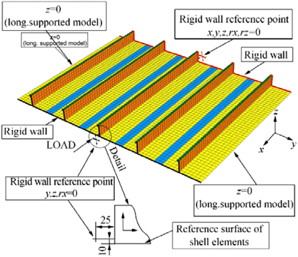 Figure 4 Simply supported boundary condition (Paulo et al. 2013)
Generally, the fully clamped conditions present overlarge stiffness of the adjacent structures and overestimate the ultimate load-carrying capacity of the panels. Meanwhile, the simple-simple support condition expresses conservative results.
4.2 Initial Imperfections
The initial imperfections comprise of initial deflections and residual stresses of the plating between the stiffeners, column-type initial distortion of the stiffener, initial sideway distortion of the stiffener and residual stress in the stiffener web. The initial deformation shape of the panels often shows the thin horse (hungry horse) mode or the form of trigonometric functions. According to the experimental test observation, the maximum magnitude of the initial deflections can be classified into three levels, namely, slight, average and severe level depending on the welding method, material properties, plating thickness and the skill of the workers (Paik et al. 2005b, 2006, 2008; Paik 2007a). The following maximum magnitudes are often used in the marine industry for aluminium alloys corresponding to the slight, average and severe level, respectively.
$$ {w}_{\mathrm{opl}}=\left\{\begin{array}{c}0.018{\beta}^2t\\ {}0.096{\beta}^2t\\ {}0.252{\beta}^2t\end{array}\right.\kern0.5em {w}_{\mathrm{oc}}=\left\{\begin{array}{c}0.00016a\\ {}0.0018a\\ {}0.0056a\end{array}\right.\kern0.5em {w}_{\mathrm{os}}=\left\{\begin{array}{c}0.00019a\\ {}0.001a\\ {}0.0024a\end{array}\right. $$ (19) where wopl is the maximum magnitude of the initial plate deflection, woc is the maximum magnitude of column-type initial deflection, wos is the maximum magnitude of the initial sideway distortion, β is the plate slenderness ratio and a and t are the length and thickness of the plate.
Three approaches are typically applied to simulate the initial deformations. The first approach is a linear elastic analysis of the panel under uniform lateral pressure. This analysis is repeated in the form of trial and error calculations by changing the lateral pressure until reaching the expected deflection of the plates. The deformation shape of the panel is the thin horse mode. This simple procedure (Figure 5) proposed by Rigo et al. (2003) was applied in many investigations (Khedmati et al. 2009, 2010a, 2010b, 2014, 2015; Pedram and Khedmati 2014; Li et al. 2018). The second approach is to superimpose three types of imperfections (plate deflection, stiffener distortion and column-type distortion) which are expressed analytically in the form of trigonometric functions (Khedmati et al. 2012). The last one is to analyse the eigenvalue buckling modes (Li et al. 2018).
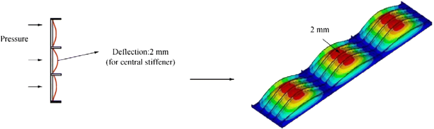 Figure 5 Initial deflections in thin horse mode (Rigo et al. 2003)
It is observed from both numerical and experimental results that the initial imperfection modes of the local plate, stiffeners and global panel govern the buckling and collapse modes of the plate and panel. The presence of initial imperfections strongly affects the structural behaviour and ultimate load-carrying capacity of the plate and stiffened panel. The buckling and ultimate failures occur earlier with the increase of initial deflections.
4.3 Residual Stresses
Tensile stresses exist in the HAZ that are self-equilibrated by the corresponding compressive stresses in the adjacent zones. Figure 6 describes the residual stress distribution in plate and stiffener, where the width of the tensile areas (also HAZ) is denoted by at in x and bt in the y-direction. The tensile stresses in the HAZ of the aluminium structure are about 50%–70% of yield stresses (Paik et al. 2005b, 2008; Collette 2007; Paik 2007a; Sielski 2008; Chen and Guedes Soares 2019; Lloyd's Register 2019b), and the compressive stresses at the stiffener web and plating are specified as slight, average and severe level based on the width of the HAZ. The relationship between the width of the HAZ and the residual stresses can be defined as follows:
$$ \mathrm{or}{\displaystyle \begin{array}{c}2{b}_{\mathrm{t}}=\frac{\sigma_{\mathrm{rcx}}}{\sigma_{\mathrm{rcx}}-{\sigma}_{\mathrm{rtx}}}b;2{a}_{\mathrm{t}}=\frac{\sigma_{\mathrm{rcy}}}{\sigma_{\mathrm{rcy}}-{\sigma}_{\mathrm{rty}}}a\\ {}{\sigma}_{\mathrm{rcx}}=\frac{2{b}_{\mathrm{t}}}{2{b}_{\mathrm{t}}-b}{\sigma}_{\mathrm{rtx}};{\sigma}_{\mathrm{rcy}}=\frac{2{a}_{\mathrm{t}}}{2{a}_{\mathrm{t}}-a}{\sigma}_{\mathrm{rty}}\end{array}} $$ (20)  Figure 6 Residual stress distribution (Paik et al. 2008)
where σrcx, σrcy, σrtx, σrty are the compressive and tensile residual stresses in the x and y directions, respectively.
The residual stresses contribute remarkably to the structural strength but do not affect the deformation, collapse and stress-strain relationship (Pedram and Khedmati 2014; Paulo et al. 2014). Interestingly, the residual stresses are noticeably released after cyclic loading in service. The reduction ratio of compressive stresses on the plate is indicated up to 36% after a few load cycles (Paik et al. 2005a). Recently, Farajkhah and Liu (2016a, 2016b), Farajkhah et al. (2016) and Farajkhah and Guedes Soares (2017) investigated the effect of different welding methods on the structural behaviour and strength of panels. The residual stresses and distortions of aluminium plates welded by FSW welding method are smaller than that by conventional MIG welding method. This results in the higher load-carrying capacity of the panels welded by FSW as compared with MIG. The residual stress decreases the buckling and ultimate strength of panels considerably.
Mohammadi et al. (2018) modified the idealized distribution of welding-induced residual stresses (Figure 6) in the welding areas, where the compressive stresses inside the plate reduce about 9%, 12% and 7% for the case of MIG, FSW and TIG welding processes, respectively, and the tensile stresses at the middle of the HAZ are smaller than that at the boundaries. The energy-method-based Fujikubo-Yao's algorithm was modified based on this proposed residual stresses distribution to assess the elastic buckling strength of stiffened plates. The results show that the elastic local buckling strength increases about 1%–5% in comparison with the idealized distribution. In addition, the buckling strength reduces significantly due to the presence of the residual stresses.
4.4 Heat-Affected Zone
The yield stress of aluminium structures, fabricated by fusion welding in the HAZ, reduces significantly in comparison with the base material. The deterioration of the yield strength in the welded areas is approximately 30%–50% of the yield strength of the unwelded material (Collette 2007; Paik 2007a; Sielski 2008; Paik et al. 2008; Lloyd's Register 2019b). The width of the HAZ (bHAZ) extends to any directions from the weld and varies with the thickness of welded plates, welding specifications, welding methods and the skill of the workers. A 25-mm width was derived from the experiments in Zha and Moan (2001), and it is typical for ship fabrications (Benson et al. 2013a; Liu et al. 2020). Three levels (11.3, 23.1 and 29.9 mm) of HAZ width were summarized and proposed by Paik et al. (2008), and 20, 30, 35 and 40-mm width are regulated by Eurocode 9 (2009) corresponding to the different thickness of the welded plates. The areas in red of Figure 7 depict different HAZ locations in conventional (model A and A + C) and integrally extruded (model B and B + C) panels. For the conventional panel, the HAZ is present at the plate-stiffener intersection and the butt-plate, and it is present at the butt and seam welds between extrusions for integrated panels.
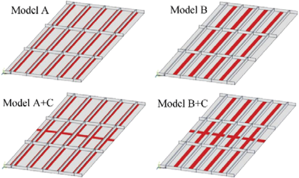 Figure 7 Models with difference in HAZ arrangement (Khedmati et al. 2010a)
The investigations on the HAZ effect showed that the presence of the welding lines, and their arrangements do not affect significantly on the initial buckling strength of the models (Khedmati et al. 2010a); however, the post-buckling behaviour and ultimate strength of the aluminium plates and stiffened panels decrease considerably due to the strength deterioration in the HAZ and the welding arrangements. This reduction is very sensitive to the width and the location of the HAZ and the amount of strength deterioration (Zha and Moan 2001, 2003; Chen and Moan 2010; Khedmati et al. 2010a, 2012; Doan et al. 2020).
5 Study on Impact of Manufacturing Technology
5.1 Fabrication
According to the manufacturing process, the aluminium stiffened panels are categorized into traditional built-up and integrated extruded stiffened panels. The first type is built by welding the stiffeners to the bare plate, while the second one is fabricated from aluminium extruded profiles by longitudinal butt welds. Each extrusion compounds plate and one/two stiffeners. Thus, the integrated stiffened panels (ISP) eliminate the need for welding in comparison with the traditional stiffened panels (TSP). Furthermore, these butt welds are typically carried out by automatic welding. Consequently, the imperfections related to fabrication of the ISP are often smaller than the TSP; this may reduce the effect of welding on the buckling and ultimate strength of the aluminium integrated panels.
It is seen that few studies were conducted on the ultimate strength of the ISP (Aalberg et al. 2001; Paulo et al. 2013; Li et al. 2018). In the present study, the ultimate strength of both aluminium stiffened panels (TSP and ISP) is analysed and compared. The analysed panels are a part of the main deck of an 80-m aluminium fast-displacement yacht. The scantlings of the structural components are given in Table 3. The spaces between stiffeners (b), frames (a) and longitudinal girders are 0.3, 1.2 and 2.1 m, respectively. For the ISP, Figure 8 shows the cross-sectional geometry of the main extruded profile that is a combination of a plate and two flat-bar stiffeners, while the longitudinal girders and the transverse frames are extruded using the I-bars and T-bars, respectively. The coordinate system and the structural geometry of the stiffened panels are presented in Figure 9.
Table 3 Scantlings of structural componentsScantlings Values (mm) Plate thickness (tp) 10 Stiffener (flat bar) 60 × 6 Transverse frame (T-bar) 150 × 8/100 × 10 Longitudinal girder (T-bar) 280 × 8/150 × 15 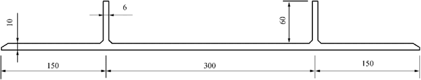 Figure 8 Cross-sectional geometry of extruded profile
 Figure 9 Coordinate system, structural geometry and boundary conditions
5.2 Finite Element Models
The analyses are performed using the finite element commercial software ANSYS, taking into account the material and geometric nonlinearities. The full Newton-Raphson algorithm for the iterative solution of nonlinear equations is used. The aluminium material 6082-T6 is selected for both plates and extruded profiles. The proof stress σ0.2 is 240 N/mm2 for the base material, and the welded yield stress is 125 N/mm2, as suggested in Lloyd's Register (2019b). The Young's modulus and Poisson's ratio of the aluminium material are 70 GPa and 0.33, respectively. The width of the HAZ along the welding lines is considered following the experimental tests carried out by Zha and Moan (2001), i.e., the 25-mm width from the welding line (Figure 10).
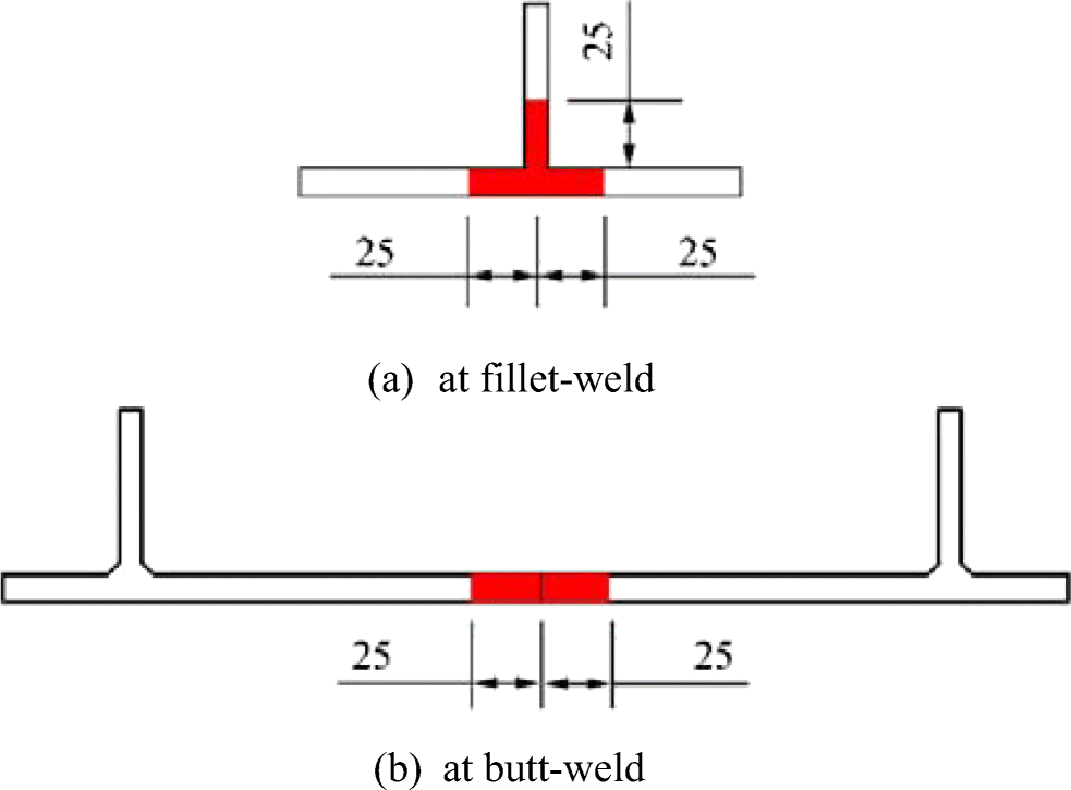 Figure 10 Width of HAZ
The actual stress-strain relationship of aluminium base material and HAZ material is usually approximated by the Ramberg-Osgood equation as expressed below (Ramberg and Osgood 1943):
$$ \varepsilon =\frac{\sigma }{E}+0.002{\left(\frac{\sigma }{\sigma_2}\right)}^n $$ (21) where n is the "knee factor" specified by physical test or using approximation techniques. It can be seen that the increase of n will result in the flatness of the stress-strain curve. For 6082-T6 alloy, n is in the range of 15–47 (n = 30 is typically used), and the stress-strain curves are close to the elastic-perfectly plastic approximation (Zha and Moan 2001; Shesharma et al. 2010; Benson et al. 2013b). Accordingly, the elastic-perfectly plastic material model is selected, and it is acceptable for the comparative study, the ultimate strength of panels that are all made of 6082-T6 alloy.
The SHELL181 element is employed. The element size of 25 mm × 25 mm is selected based on the results of mesh convergence test from previous research work of the authors (Doan et al. 2020) considering the balance between the computational time and calculated accuracy. This element size is fine enough to ensure precisely describing the deformation of the model and to assess the influence of the HAZ properly. The finite element models are presented in Figure 11. To evaluate the effect of the HAZ on the ultimate strength of the aluminium panel, a case without considering the HAZ (SP-W0) is also analysed.
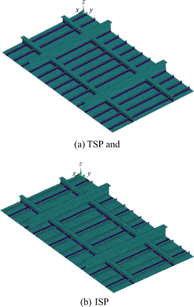 Figure 11 Finite element models
5.2.1 Initial Imperfections
Different fabrication processes may induce different welding-induced initial imperfections on the panels. However, similar imperfections are assumed in the present study. The equivalent initial defects are adopted by superimposing the three types of distortions from the eigenvalue buckling analysis (Figures 12 and 13). The average level of the maximum amplitudes corresponding to the local plate deflection wopl, column-type distortion of the stiffener woc and the sideway distortion of the stiffener wos are selected for both panels as 0.096β2tp = 2.73 mm, 0.0018a = 2.16 mm and 0.001a = 1.2 mm, respectively (Paik et al. 2006, 2008). Here, the welding-induced residual stresses are ignored.
 Figure 12 Local deflection of plate and sideway distortion of stiffener
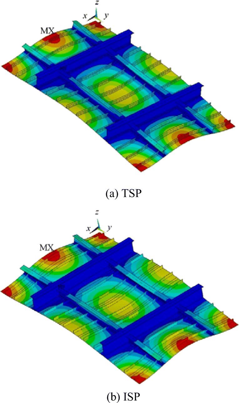 Figure 13 Column-type distortion of the stiffeners
5.2.2 Boundary Conditions
It is important to apply adequate boundary conditions in the longitudinal and transverse directions of the FE model since they significantly affect the structural behaviour and ultimate strength of the panels. Three types of boundary conditions have been applied in the two halves plus one full (1/2 + 1 + 1/2) bays model, and they are simply supported, fully clamped and periodical. The first two types of boundary conditions seem to overestimate the contribution of the adjacent structures. This leads to a different collapse mode and overestimates the loading capacity of the panel, while the periodical boundary conditions give logical modelling in considering the continuity of the structures (Xu et al. 2013; Yao and Fujikubo 2016). Hence, the periodical boundary conditions are imposed at the loaded edges (longitudinal direction), and the symmetrical boundary conditions are imposed at the unloaded edges (transversal direction) (Figure 9). It means that all nodes on the loaded edge (AE) are coupled corresponding to the nodes on the DH edge to have the same displacement and rotation. The in-plane movement of the loaded and unloaded edges is assumed to be uniform in their perpendicular directions. The detailed descriptions are defined as follows:
Periodical condition: uniform uxAE, uxDH = 0, uyAE = uyDH, uzAE = uzDH, rotxAE = rotxDH, rotyAE = rotyDH, rotzAE = rotzDH = 0.
Symmetrical condition: uniform uyEH, uyAD = 0, rotxAD = rotxEH = rotzAD = rotzEH = 0.
Four nodes B, C, F and G on the frames are fixed in the z-direction to prevent the rigid-body motion: uz = 0.
The forced displacement ux is applied to the loaded edge AE in the large deformation nonlinear analyses.
5.3 Results and Discussion
Figure 14 shows the load-shortening curves of three panels subjected to uniaxial compression, and Table 4 gives the ultimate compressive strength of three panels. Generally, the loading process of the three panels is similar, and it can be divided into three regions. In the beginning, the compressive load increases linearly with the increase of the axial displacement. When the compressive load reaches a critical value, the first buckle occurs, and from this point ahead, three loading curves gradually turn into the plastic region, and the axial strain rate increases. Afterwards, the compressive load continues to increase in this region until reaching the ultimate compressive strength. As a result, the stiffness reduction of the panels leads to a decrease in the load-carrying capacity in the third region (post-ultimate).
 Figure 14 Load-shortening curvesTable 4 Compressive load and vertical deflection at the ultimate limit state
Panels Ultimate strength (kN) Difference (%) Vertical deflection uz (mm) SP-W0 5189 0 45.13 ISP 5002 3.6 43.05 TSP 4784 7.8 42.66 The compressive load-carrying capacity of the integrated extruded stiffened panel (ISP) is relatively higher than that of the traditional stiffened panel with HAZ (TSP) in the entire loading process. The ultimate compressive strength of the ISP is 5002kN, approximately 4.6% higher than that of the TSP (4784 kN). Interestingly, the behaviour of the ISP is similar to the panel without HAZ (SP-W0) in the linear regime and at the beginning of the plastic regime. The ultimate strength of the ISP is approximately 3.6% smaller than that of the SP-W0 (5189 kN). It proves that the HAZ effect on the ultimate compressive strength of the panels is significant.
The deformation and stress distribution of three panels at the ultimate limit state are shown in Figures 15, 16 and 17. As the same initial imperfections are used, the deformation of these panels, during the loading process, is almost the same. The panel between longitudinal girders and transverse frames buckles first as a unit in the elastic regime. This is possible because the dimensions of the stiffeners are small so that they buckle together with the plating. Then, the stiffeners located in the compression side undergo distortion at the mid-span, and the local buckling of the web of the longitudinal girders takes place, resulting in instability of the entire structures. Finally, three panels collapse in the form of column-type failure mode. Nevertheless, the sideway distortion of the stiffeners of the TSP is much larger than that of the ISP and SP-W0. It is probably due to the effect of the strength deterioration in the HAZ of the stiffener web in the TSP.
 Figure 15 Deformation and von-Mises stress distribution at ultimate limit state of TSP
 Figure 16 Deformation and von-Mises stress distribution at ultimate limit state of ISP
 Figure 17 Deformation and von-Mises stress distribution at ultimate limit state of SP-W0
Regarding the deflections of the panels, the axial strain of the three panels is almost the same (Figure 14). At the ultimate limit state, their axial displacements are around 7.0 mm (7.04, 6.95 and 6.93 mm for ISP, TSP and SP-W0, respectively). Meanwhile, the vertical deflection of the central node (uz displacement) at the ultimate limit state of the ISP (43.05 mm) is about 4.6% smaller than that of the TSP (45.13 mm) and about 0.9% higher than that of the SP-W0 (42.66 mm). This reveals that the HAZ in the transverse and vertical directions has a considerable influence on the lateral deflection but has a negligible effect on the longitudinal displacement of the panels subjected to axial compression.
Furthermore, Figures 15, 16 and 17 reveal that the von-Mises stress distribution at the ultimate limit state of the ISP is very similar to the SP-W0 and is slightly different from the TSP. The maximum level of stresses in the ISP and the SP-W0 is concentrated at the mid-span of the stiffeners and the intersection between longitudinal girders and deck plating. While in the TSP, the maximum level of stresses is not only present at the mid-span of the stiffeners but also spreads to large areas on the plates. It demonstrates that the strength deterioration in the HAZ reduces the stiffness of the plate.
6 Conclusions
The study presented here reviewed the ultimate compressive strength of aluminium plates and stiffened panels, discussing the ultimate strength analysis using analytical, empirical, numerical and experimental methods. The advantage and disadvantage of these methods are summarized as follows:
6.1 Analytical Approach
• Advantage: It can assess the buckling and ultimate strength of plated structures rapidly.
• Disadvantage: It is only used for well-defined cases.
6.2 Empirical Formulation
• Advantage: It can assess the buckling and ultimate strength of plated structures rapidly.
• Disadvantage: It is applied for not very complicated objects, and the accuracy of each formulation depends on the amount of the collected data.
6.3 Experimental Test
• Advantage: It presents the most reliable values.
• Disadvantage: It is the most expensive and timeconsuming approach; it is difficult to fulfil the geometrical similitude between the scaled model and its full-scale prototype due to some limitations in manufacturing.
6.4 Numerical Method
• Advantage: It is considered as the most powerful tool for analysing the nonlinear behaviour of the structural system. It allows in solving many practical problems, especially with the complex structures. Moreover, it allows changing the calculating conditions, such as boundary conditions, load and material property quickly.
• Disadvantage: The accuracy of the finite element results is highly dependent on the skill of the analysts, and it is timeconsuming for analysing complex structures.
The structural behaviour and ultimate strength of aluminium stiffened panels are very sensitive to the boundary conditions, initial deflections, welding-induced residual stresses and HAZ. The effects of these parameters were also briefly summarized. In addition, the influence of other governing parameters, such as loading, structural changes and in-service degradation (corrosion or crack) is essential and should be further investigated, for example, Liu and Guedes Soares (2020).
The integrated extruded stiffened panel exhibits higher ultimate strength than the traditional welded stiffened panel under axial compression. The fabricating process takes an essential part in changing the distribution of the HAZ, which results in significant effects on the stress distribution, vertical deflection and load-carrying capacity of the panels. Moreover, the initial deflections and welding-induced residual stresses are affected by fabricating technology. However, the investigations on the initial imperfections and their effects related to integrated extruded stiffened panels are still limited and should be further investigated.
Open Access This article is licensed under a Creative Commons Attribution 4.0 International License, which permits use, sharing, adaptation, distribution and reproduction in any medium or format, as long as you give appropriate credit to the original author(s) and the source, provide a link to the Creative Commons licence, and indicate if changes were made. The images or other third party material in this article are included in the article's Creative Commons licence, unless indicated otherwise in a credit line to the material. If material is not included in the article's Creative Commons licence and your intended use is not permitted by statutory regulation or exceeds the permitted use, you will need to obtain permission directly from the copyright holder. To view a copy of this licence, visit http://creativecommons.org/licenses/by/4.0/. -
Figure 1 Collapse test of stiffened panel (Aalberg et al. 2001)
Figure 2 Transversely stiffened aluminium panel tested by Rønning et al. (2010)
Figure 3 Distortions and stress distributions at ultimate limit state (Khedmati et al. 2009)
Figure 4 Simply supported boundary condition (Paulo et al. 2013)
Figure 5 Initial deflections in thin horse mode (Rigo et al. 2003)
Figure 6 Residual stress distribution (Paik et al. 2008)
Figure 7 Models with difference in HAZ arrangement (Khedmati et al. 2010a)
Figure 8 Cross-sectional geometry of extruded profile
Figure 9 Coordinate system, structural geometry and boundary conditions
Figure 10 Width of HAZ
Figure 11 Finite element models
Figure 12 Local deflection of plate and sideway distortion of stiffener
Figure 13 Column-type distortion of the stiffeners
Figure 14 Load-shortening curves
Figure 15 Deformation and von-Mises stress distribution at ultimate limit state of TSP
Figure 16 Deformation and von-Mises stress distribution at ultimate limit state of ISP
Figure 17 Deformation and von-Mises stress distribution at ultimate limit state of SP-W0
Table 1 Numerical codes and their application (ISSC 2018)
Numerical code Organization Component applicability ABAQUS Abaqus Inc. Stiffened/unstiffened panel ALPS/ULSAP Pusan National University Stiffened/unstiffened panel ANSYS Ansys Inc. Stiffened/unstiffened panel BV Adv. Buckling Bureau Veritas Stiffened panel DNV/PULS DNV-GL Stiffened/unstiffened panel MSC/MARC MSC Stiffened/unstiffened panel Table 2 Summary of different boundary conditions
Models BC at loaded edges BC at unloaded edges Applications Description Plate Simply supported Simply supported Conley et al. (1963); Mofflin (1983); Wang et al. (2005); Collette et al. (2008); Benson et al. (2011; 2013) Loaded edges:
x = 0: ux = uy = uz = 0; rotx = rotz = 0
x = l: uy = uz = 0; rotx = rotz = 0
Unloaded edges:
y = 0: uy = uz = 0
y = b: uz = 0Simply supported free Seifi and Khoda-yari (2011) Loaded edges:
x = 0: ux = uy = uz = 0; rotx = rotz = 0
x = l: uy = uz = 0; rotx = rotz = 0One-bay panel Simply supported Simply supported Aalberg et al. (2001); Zha and Moan (2001, 2003); Paik et al. (2008, 2012); Khedmati et al. (2009); Rønning et al. (2010); Paulo et al. (2013); Li et al. (2018); Ren et al. (2018) Loaded edges:
x = 0: ux = uy = uz = 0; rotx = rotz = 0
x = l: uy = uz = 0; rotx = rotz = 0
Unloaded edges:
y = 0: uz = 0
y = B: uz = 0Simply supported Free Paik et al. (2008) Loaded edges:
x = 0: ux = uy = uz = 0; rotx = rotz = 0
x = l: uy = uz = 0; rotx = rotz = 0(1/2 + 1 + 1/2) Bay panel Periodic Symmetric Doan et al. (2020) Loaded edges:
ux0 = 0; ux2l uniform; equal uy; equal uz; equal rotx; equal roty; rotz = 0
Unloaded edges:
uy0 = 0; uy2B uniform;
y = 0: uzx = l/2 = 0; uzx = 3l/2 = 0; rotx = rotz = 0
y = 2B: uzx = l/2 = 0; uzx = 3l/2 = 0; rotx = rotz = 0Fully clamped Fully clamped Li et al. 2017 Loaded edges:
x = 0: ux = uy = uz = 0; rotx = roty = rotz = 0
x = 2 l: uy = uz = 0; rotx = roty = rotz = 0
Unloaded edges:
y = 0: uy = uz = 0; rotx = roty = rotz = 0
y = 2B: uz = 0; rotx = roty = rotz = 0Three-bay panel Fully clamped Fully clamped Li et al. (2017) Loaded edges:
x = 0: ux = uy = uz = 0; rotx = roty = rotz = 0
x = 3 l: uy = uz = 0; rotx = roty = rotz = 0
Unloaded edges:
y = 0: uy = uz = 0; rotx = roty = rotz = 0
y = 3B: uz = 0; rotx = roty = rotz = 0Simply supported Partially constrained Rigo et al. (2003); Paik et al. (2008); Khedmati and Ghavami (2009); Khedmati et al. (2010a, 2012); Pedram and Khedmati et al. (2014) Loaded edges:
x = 0: ux = uz = 0; rotx = rotz = 0
x = 3 l: uz = 0; rotx = rotz = 0
Unloaded edges:
y = 0; y = 3B: uniform uyux, uy, uz, rotx, roty and rotz are the displacement and rotation in longitudinal x, transverse y and vertical z directions, respectively; l is the span of the panels; B is the distance between longitudinal girders Table 3 Scantlings of structural components
Scantlings Values (mm) Plate thickness (tp) 10 Stiffener (flat bar) 60 × 6 Transverse frame (T-bar) 150 × 8/100 × 10 Longitudinal girder (T-bar) 280 × 8/150 × 15 Table 4 Compressive load and vertical deflection at the ultimate limit state
Panels Ultimate strength (kN) Difference (%) Vertical deflection uz (mm) SP-W0 5189 0 45.13 ISP 5002 3.6 43.05 TSP 4784 7.8 42.66 -
Aalberg A, Langseth M, Larsen PK (2001) Stiffened aluminium panels subjected to axial compression. Thin-Walled Struct 39: 861–885. https://doi.org/10.1016/S0263-8231(01)00021-0 Benson S, Downes J, Dow RS (2011) Ultimate strength characteristics of aluminium plates for high-speed vessels. Ships Offshore Structures 6(1–2): 67–80. https://doi.org/10.1080/17445302.2010.529696 Benson S, AbuBakar A, Dow RS (2013a) A comparison of computational methods to predict the progressive collapse behaviour of a damaged box girder. Eng Struct 48: 266–280. https://doi.org/10.1016/j.engstruct.2012.09.031 Benson S, Downes J, Dow RS (2013b) Load shortening characteristics of marine-grade aluminium alloy plates in longitudinal compression. Thin-Walled Struct 70: 19–32. https://doi.org/10.1016/j.tws.2013.04.006 Benson S, Downes J, Dow RS (2013c) Compartment level progressive collapse analysis of lightweight ship structures. Mar Struct 31: 44–62. https://doi.org/10.1016/j.marstruc.2013.01.001 Benson S, Downes J, Dow RS (2015) Overall buckling of lightweight stiffened panels using an adapted orthotropic plate method. Eng Struct 85: 107–117. https://doi.org/10.1016/j.engstruct.2014.12.017 Chen BQ, Guedes Soares C (2019) Numerical investigation on weld-induced imperfections in aluminium ship plates. J Offshore Mech Arctic Eng 141(6): 061605. https://doi.org/10.1115/1.4043778 Chen Q, Moan T (2010) Material softening effect on ultimate strength of stiffened aluminium panels. In: In: Proceedings of the 29th International Conference on Ocean. Offshore and Arctic Engineering (OMAE2010), Shanghai. https://doi.org/10.1115/OMAE2010-20979 Collette M (2005) Strength and reliability of aluminium stiffened panels, PhD thesis, School of Marine Science and Technology, Faculty of Science, Agriculture and Engineering. University of Newcastle, Newcastle, UK Collette MD (2007) The impact of fusion welds on the ultimate strength of aluminum structures. In: Proceedings of the 10th International Symposium on Practical Design of Ships and Other Floating Structures, Texas, USA. 10.1.1.469.6499 Collette M, Wang X, J. Li, J Walters, Yen T (2008) Ultimate strength and optimisation of aluminium extrusions, SAIC, MD 20716, USA, Ship Structure Committee Final Report No SSC-454 Conley WF, Becker LA, Allnutt RB (1963) Buckling and ultimate strength of plating loaded in edge compression. Progress report 2 - unstiffened panels, structural mechanics laboratory, Department of the Navy - David Taylor Model Basin, USA no. 1682 Doan VT, Liu B, Garbatov Y, Wu W, Guedes Soares C (2020) Strength assessment of aluminium and steel stiffened panels with openings on longitudinal girders. Ocean Eng 200: 107047. https://doi.org/10.1016/j.oceaneng.2020.107047 Eurocode 9 (2009) Design of aluminium structures - part 1-1: general structural rules, EN1999-1-1: 2007+A1. In: European Committee for Standardization (CEN). Belgium, Brussels Farajkhah V, Guedes Soares C (2017) Finite element study on the ultimate strength of aluminum plates joined by friction stir welding. In: Guedes Soares C, Garbatov Y (eds) Progress in the Analysis and Design of Marine Structures. Taylor & Francis, London, pp 609–615 Farajkhah V, Liu Y (2016a) Effect of fabrication methods on the ultimate strength of aluminum hull girders. Ocean Eng 114(Supplement C): 269–279. https://doi.org/10.1016/j.oceaneng.2016.01.029 Farajkhah V, Liu Y (2016b) Effect of metal inert gas welding on the behaviour and strength of aluminum stiffened plates. Mar Struct 50: 95–110. https://doi.org/10.1016/j.marstruc.2016.07.005 Farajkhah V, Liu Y, Gannon L (2016) Finite element study of 3D simulated welding effect in aluminium plates. Ships Offshore Structures 12(2): 196–208. https://doi.org/10.1080/17445302.2015.1123865 Faulkner D (1975) A review of effective plating for use in the analysis of stiffened plating in bending and compression. J Ship Res 19(1): 1–17 https://doi.org/10.5957/jsr.1975.19.1.1 Guedes Soares C, Soreide TH (1983) Behaviour and design of stiffened plates under predominantly compressive loads. Int Shipbuild Prog 30(341): 13–26 https://doi.org/10.3233/ISP-1983-3034103 Guedes Soares C, Dogliani M, Ostergaard C, Parmentier G, Pedersen PT (1996) Reliability based ship structural design. Trans Soc Naval Architects Mar Eng (SNAME) 104: 357–389 ISSC (2018) Report of technical committee: ultimate strength III. 1. In: Kaminski ML, Rigo P (eds) In: proceedings of the 20th international ship and offshore structures congress. The Netherlands, Amsterdam Kasten, M (2016) Strength of aluminum vs strength of steel. http://www.kastenmarine.com/alumVSsteel.htm Khedmati MR, Ghavami K (2009) A numerical assessment of the buckling/ultimate strength characteristics of stiffened aluminium plates with fixed/floating transverse frames. Thin-Walled Struct 47(11): 1373–1386. https://doi.org/10.1016/j.tws.2009.03.008 Khedmati MR, Zareei MR, Rigo P (2009) Sensitivity analysis on the elastic buckling and ultimate strength of continuous stiffened aluminium plates under combined in-plane compression and lateral pressure. Thin-Walled Struct 47(11): 1232–1245. https://doi.org/10.1016/j.tws.2009.04.010 Khedmati MR, Bayatfar A, Rigo P (2010a) Post-buckling behaviour and strength of multi-stiffened aluminium panels under combined axial compression and lateral pressure. Mar Struct 23(1): 39–66. https://doi.org/10.1016/j.marstruc.2009.10.003 Khedmati MR, Zareei MR, Rigo P (2010b) Empirical formulations for estimation of ultimate strength of continuous stiffened aluminium plates under combined in-plane compression and lateral pressure. Thin-Walled Struct 48(3): 274–289. https://doi.org/10.1016/j.tws.2009.10.001 Khedmati MR, Pedram M, Rigo P (2012) The effects of geometrical imperfections on the ultimate strength of aluminium stiffened plates subject to combined uniaxial compression and lateral pressure. Ships Offshore Struct 9(1): 88–109. https://doi.org/10.1080/17445302.2012.726761 Khedmati MR, Memarian HR, Fadavie M, Zareei MR (2014) Empirical formulations for estimation of ultimate strength of continuous aluminium stiffened plates under combined transverse compression and lateral pressure. Ships Offshore Struct 11(3): 258–277. https://doi.org/10.1080/17445302.2014.985430 Khedmati MR, Memarian HR, Fadavie M, Zareei MR (2015) Ultimate strength of continuous stiffened aluminium plates under combined biaxial compression and lateral pressure. Latin Am J Solids Struct 12(9): 1698–1720. https://doi.org/10.1590/1679-78251516 Kim DK, Lim HL, Yu SY (2018) A technical review on ultimate strength prediction of stiffened panels in axial compression. Ocean Eng 170: 392–406. https://doi.org/10.1016/j.oceaneng.2018.10.022 Kristensen OHH (2001) Ultimate capacity of aluminium plates under multiple loads considering HAZ properties, PhD thesis, Department of Marine Structures, Faculty of Marine Technology. Norwegian University of Science and Technology, Trondheim, Norway Li C, Zhu Z, Ren H, Guedes Soares C (2017) Finite element analysis of the ultimate strength of aluminium-stiffened panels with fixed and floating transverse frames. J Offshore Mech Arctic Eng 139(4): 041401. https://doi.org/10.1115/1.4036111 Li C, Ren H, Zhu Z, Guedes Soares C (2018) Numerical investigation on the ultimate strength of aluminium integrally stiffened panels subjected to uniaxial compressive load. Thin-Walled Struct 127: 221–234. https://doi.org/10.1016/j.tws.2018.01.003 Liu B, Guedes Soares C (2020) Ultimate strength assessment of ship hull structures subjected to cyclic bending moments. Ocean Eng 215: 107685. https://doi.org/10.1016/j.oceaneng.2020.107685 Liu B, Villavicencio R, Liu K, Zhu L, Guedes Soares C (2019) Response of an aluminum stiffened plate under extreme slamming loadings. J Offshore Mech Arctic Eng 141(5): 051606. https://doi.org/10.1115/1.4042389 Liu B, Liu K, Villavicencio R, Dong A, Guedes Soares C (2020) Experimental and numerical analysis of the penetration of welded aluminium alloy panels. Ships Offshore Structures: 1–13. https://doi.org/10.1080/17445302.2020.1736856 Lloyd's Register (2019a) Rules and regulations for the classification of special service craft. Lloyd's Register, London Lloyd's Register (2019b) Rules for the manufacture, testing and certification of materials. Lloyd's Register, London Mofflin, DS (1983). Plate buckling in steel and aluminium, PhD thesis, Department of Engineering, Cambridge University, UK Mohammadi M, Khedmati MR, Bahmyari E (2018) Elastic local buckling strength analysis of stiffened aluminium plates with an emphasis on the initial deflections and welding residual stresses. Ships Offshore Struct 14(2): 125–140. https://doi.org/10.1080/17445302.2018.1482061 Paik JK (2007a) Characteristics of welding induced initial deflections in welded aluminum plates. Thin-Walled Struct 45(5): 493–501. https://doi.org/10.1016/j.tws.2007.04.009 Paik JK (2007b) Empirical formulations for predicting the ultimate compressive strength of welded aluminum stiffened panels. Thin-Walled Struct 45(2): 171–184. https://doi.org/10.1016/j.tws.2007.02.003 Paik JK (2018). Ultimate limit state analysis and design of plated structures. 2nd ed. John Wiley & Sons Paik J, Duran A (2004) Ultimate strength of aluminum plates and stiffened panels for marine applications. Mar Technol 41: 108–121 Paik JK, Hughes OF, Hess PE, Renaud C (2005a) Ultimate limit state design technology for aluminium multi-hull ship structures. SNAME Trans 113: 270–305 Paik JK, van der Veen S, Duran A, Collette M (2005b) Ultimate compressive strength design methods of aluminum welded stiffened panel structures for aerospace, marine and land-based applications: a benchmark study. Thin-Walled Struct 43(10): 1550–1566. https://doi.org/10.1016/j.tws.2005.06.003 Paik JK, Thayamballi AK, Ryu JY, Jang JH, Seo JK, Park SW, Seo SK, Renaud C, Cojeen HP, Kim NI (2006) The statistics of weld induced initial imperfections in aluminium stiffened plate structures for marine applications. Trans R Instit Naval Architects Part A: International Journal of Maritime Engineering 148: 19–62 Paik JK, Thayamballi AK, Ryu JY, Jang JH, Seo JK, Park SW, Soe SK, Renaud C, Kim NI (2008) Mechanical collapse testing on aluminum stiffened panels for marine applications. Ship structure committee final report no. SSC-451, Pusan Paik JK, Kim BJ, Sohn JM, Kim SH, Jeong JM, Park JS (2012) On buckling collapse of a fusion-welded aluminum-stiffened plate structure: an experimental and numerical study. J Offshore Mech Arctic Eng 134(2): 021402. https://doi.org/10.1115/1.4004511 Paulo RMF, Teixeira-Dias F, Valente RAF (2013) Numerical simulation of aluminium stiffened panels subjected to axial compression: sensitivity analyses to initial geometrical imperfections and material properties. Thin-Walled Struct 62:65–74. https://doi.org/10.1016/j.tws.2012.07.024 Paulo RMF, Carlone P, Valente RAF, Teixeira-Dias F, Palazzo GS (2014) Influence of friction stir welding residual stresses on the compressive strength of aluminium alloy plates. Thin-Walled Struct 74:184–190. https://doi.org/10.1016/j.tws.2013.09.012 Pedram M, Khedmati MR (2014) The effect of welding on the strength of aluminium stiffened plates subject to combined uniaxial compression and lateral pressure. Int J Naval Archit Ocean Eng 6(1): 39–59. https://doi.org/10.2478/ijnaoe-2013-0162 Ramberg W, Osgood WR (1943) Description of stress-strain curves by three parameters, Washington, USA No 902 Ren H, Liu Y, Li C, Zhang X, Wu Z (2018) Numerical investigation of ultimate strength of stiffened plates with various cross-section forms. In: Proceedings of the 37th International Conference on Ocean, Offshore and Arctic Engineering (OMAE), Madrid. https://doi.org/10.1115/OMAE2018-77756 Rigo P, Sarghiuta R, Estefen S, Lehmann E, Otelea SC, Pasqualino I, Simonsen BC, Wan Z, Yao T (2003) Sensitivity analysis on ultimate strength of aluminium stiffened panels. Mar Struct 16(6): 437–468. https://doi.org/10.1016/j.marstruc.2003.09.002 Rønning L, Aalberg A, Larsen PK (2010) An experimental study of ultimate compressive strength of transversely stiffened aluminium panels. Thin-Walled Struct 48(6): 357–372. https://doi.org/10.1016/j.tws.2010.01.015 Seifi R, Khoda-yari N (2011) Experimental and numerical studies on buckling of cracked thin-plates under full and partial compression edge loading. Thin-Walled Struct 49(12): 1504–1516. https://doi.org/10.1016/j.tws.2011.07.010 Shesharma P, Collette M, Harrington J (2010) Effect of welded properties on aluminium structures, USA no. SSC-4 Sielski RA (2008) Research needs in aluminum structure. Ships Offshore Struct 3(1): 57–65. https://doi.org/10.1080/17445300701797111 Syrigou MS, Dow RS (2018) Strength of steel and aluminium alloy ship plating under combined shear and compression/tension. Eng Struct 166:128–141. https://doi.org/10.1016/j.engstruct.2018.03.051 Wang X, Sun H, Akiyama A, Du A (2005) Buckling and ultimate strength of aluminium plates and stiffened panels in marine structures. In: the 5th International Forum on Aluminium Ships, Tokyo, Japan Xu MC, Yanagihara D, Fujikubo M, Guedes Soares C (2013) Influence of boundary conditions on the collapse behaviour of stiffened panels under combined loads. Mar Struct 34:205–225. https://doi.org/10.1016/j.marstruc.2013.09.002 Yao T, Fujikubo M (2016) Buckling and ultimate strength of ship and ship-like floating structures. Elsevier Zha Y, Moan T (2001) Ultimate strength of stiffened aluminium panels with predominantly torsional failure modes. Thin-Walled Struct 39:631–648. https://doi.org/10.1016/S0263-8231(01)00027-1 Zha Y, Moan T (2003) Experimental and numerical prediction of collapse of flat bar stiffeners in aluminum panels. Struct Eng 129:160–168. https://doi.org/10.1061/(ASCE)0733-9445/2003/129:2/160 Zhang S (2015) A review and study on ultimate strength of steel plates and stiffened panels in axial compression. Ships and Offshore Structures, 1–11. https://doi.org/10.1080/17445302.2014.992610