All-Electric Subsea Control Systems and the Effects on Subsea Manifold Valves
https://doi.org/10.1007/s11804-020-00155-1
-
Abstract
Subsea development is moving constantly toward simplification, digitalization, and cost-out strategies because the exploration and production of hydrocarbons are moving toward deeper and remote sea water areas. Usage of all-electric subsea technology instead of hydraulic technology is growing and will be the future of subsea systems due to the former's environmental and functional advantages and reduced costs. The benefits of all-electric subsea systems are health, safety, and environment (HSE) and improved reliability, flexibility, and functionality compared with traditional hydraulic-electrical systems. Existing electrohydraulic technology for a typical subsea system, hydraulic and electric actuators, and subsea manifold valves including valve types and selection philosophy have been reviewed in this paper. Some major worldwide oil companies such as Equinor and Schlumberger have successful experiences with subsea electric actuators. Considering the benefits of all-electric technology especially in terms of cost and HSE, as well as successful experiences of two major oil companies, further research in this area is warranted. One of the gaps in existing reviewed literature is the effect of using all-electric actuators for manifold valves. Thus, three main questions related to electric actuator selection, requirement of safety integrity level (SIL), and effect of using electric actuators on manifold valve selection have been addressed and answered. Forty hydraulic actuated manifold valves from nine past subsea projects in different parts of the world, mainly Africa and Australia, have been selected for the analysis of all-electric actuators. Results show that 93% of the valves require spring-return electric actuators, whereas 7% can be operated with conventional electric actuators without any spring. The manifold valves do not require SIL certification because they are not connected to an emergency shut down system. Introducing the electric actuators to the manifold valve will not change the valve selection philosophy.-
Keywords:
- Subsea oil and gas ·
- Production ·
- Manifold ·
- Industrial valves ·
- Electric actuators ·
- Oil and gas ·
- Offshore ·
- Marine environment
Article Highlights• Electrical actuators also called motor could be supplied with spring for achieving fail safe close mode of operation.• Changing the actuators from hydraulic to electrical in subsea manifolds does not bring any safety integrity level requirements for the actuated valves.• There is no safety integrity level (SIL) is associated with manifold valves.• All electrical subsea system and actuation reduces the cost and provide higher environmentally solution compared to hydraulic and electrical subsea system. -
1 Introduction
Subsea development is moving constantly toward simplification, digitalization, and cost-out strategies (Abicht and Halvorsen 2017) because the exploration and production of hydrocarbons are gearing toward deeper and remote sea water areas. Usage of all-electric subsea technology is constantly growing and will be the future of subsea systems due to its environmental and functional advantages and reduced costs. The all-electric control system eliminates the need for traditional hydraulic control systems (Bai and Bai 2012). Electric subsea development without hydraulic technology is an environmentally friendly and attractive solution with respect to health, safety, and environment (HSE) (Abicht and Halvorsen 2017). Removing hydraulic fluid prevents the exposure of hydraulic to the operators and personnel involving different tasks relevant to the hydraulic system, such as equipment production, testing, transport, offshore handling, maintenance, and operation (Abicht and Halvorsen 2017). The benefits of all-electric control systems are not limited to HSE (Larsen et al. 2016). Other advantages such as cost and improved reliability, flexibility, and functionality have been mentioned in the current literature (Larsen et al. 2016). The reliability of the hydraulic actuator can be jeopardized due to contamination in the hydraulic, which can damage solenoid valves in the hydraulic system and actuators (Larsen et al. 2016). Electric actuators have many parts that can fail, but they have dual redundancy to a large extent (Larsen et al. 2016). The other advantage that adds reliability to electric actuators is the possibility of monitoring the actuators' position (e.g., 10% from the closed position) from the host facilities (control room) topside (Larsen et al. 2016). A joint study between British Petroleum, Cameron, and an engineering group at Cranfield University was organized in 2004 to evaluate and compare the reliability values between all-electric and electrohydraulic subsea control systems (Theobald 2005).The analysis was conducted on a subsea system with four wells, and the reliability of these two systems was estimated and compared in Table 1 in terms of availability (no failure scenario). AET and EHT stand for all-electric technology and electrohydraulic technology, respectively. All-electric systems offer a high degree of flexibility when expanding the current field or adding new equipment to the subsea system (Bai and Bai 2012).
Table 1 AET and EHT reliability comparision (Theobald 2005)Production percentage Number of active wells AET availability percentage EHT availability percentage 100 4 86.5 84.3 > 75 3 or 4 96.9 96.4 > 50 2 or 3 or 4 97.5 97.0 > 25 1 or 2 or 3 or 4 97.5 97.0 2 Existing EHT VS AET in a Typical Subsea System
This section explains and compares traditional electrohydraulic and all-electric control systems, as well as provides some facts and figures about the functionality of the all-electric system (Bai and Bai 2012).
A subsea production system consists of subsea completed well(s), seabed wellhead(s), production tree(s), subsea tie-ins to a flow line system, and subsea equipment and control facilities to operate the well(s) (Bai and Bai 2012). A typical subsea field architecture is illustrated in Figure 1. The figure includes subsea structures and equipment such as subsea manifolds, pipeline ends, inline structures, jumpers, subsea wellheads, subsea trees, umbilical systems, production risers, and subsea pipeline (Bai and Bai 2012).
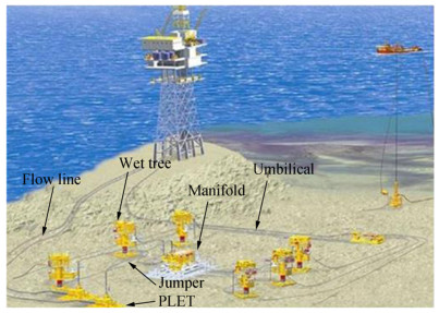 Figure 1 Typical subsea production system (Courtesy: Elsevier)
The pressure-containing components at the surface of an oil and gas well that provide interface for drilling, completion, and testing of the well, as well as production equipment, are collectively known as the wellhead. The surface pressure control of the wellhead is done by a "Christmas tree, " which is the assembly of valves, pipes, and fittings. Subsea manifolds (Figure 2) are used to simplify the subsea system by minimizing the usage of a subsea pipeline and risers, as well as optimizing fluid flow (Bai and Bai 2012). The manifold structure is an arrangement of piping and valves designed to integrate, distribute, and control the fluid flow (Bai and Bai 2012). Manifolds are installed on the seabed to gather production from different wells or inject water or gas into the wells for advanced oil recovery (Bai and Bai 2012).
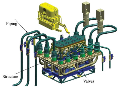 Figure 2 Subsea manifold (Courtesy: Subsea Enginerring Handbook)
The current control system for most of the subsea development units including actuated valves is standardized as multiplex electrohydraulic (Theobald 2005). The subsea control system operates the actuated valves in different subsea sections such as manifolds and Christmas trees. The electrohydraulic system connects many subsea control modules (SCMs) to be connected to supply lines of electrical, hydraulic, and communication (Bai and Bai 2012; Theobald 2005). The source of hydraulic and electricity is typically either topside host platform or ship facility. Umbilical (Figure 3) is the combination of cables and hoses used to transfer hydraulic, electrical power, and signals to subsea (Bai and Bai 2012). Figure 4 provides an overview of the main building blocks in a typical electrohydraulic control system (Society for Underwater Technology 2008). Solenoid valves are electromechanical devices that are energized with electrical power to open the fluid flow toward the hydraulic actuators (See Figure 5, typical electrohydraulic control system). The electrohydraulic control system can measure flow, temperature, and pressure and report the values to the control room by sending signals (Bai and Bai 2012).
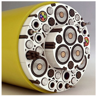 Figure 3 Subsea umbilical (Source: Aker Solutions website)
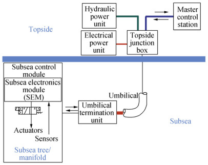 Figure 4 Subsea control for topside and subsea (Source: Subsea Engineering Handbook)
 Figure 5 Electrohydraulic control system (Source: Subsea Engineering Handbook)
An all-electric subsea system is simple and inexpensive because the hydraulic-related equipment and components are eliminated. The reduction in costs by using an all-electric system is achieved through simplifying subsea production system, cost reduction in umbilical, as well as hydraulic power unit and SCMs (Larsen et al. 2016). The additional cost due of introducing an all-electric system, including electric actuators, is in the form of electrical power unit and more subsea power distribution, as well as more tests on electric actuators (Larsen et al. 2016).
3 Oil Operators' Experiences with Electric Actuators
Some main oil operator companies have reported good operational experience with subsea electric actuators (Abicht and Halvorsen 2017; One subsea, A Schlumberger Company 2019). Schlumberger, which is the largest oilfield service company in the world, has experienced more than 1000000 h of subsea electric actuator operation designed for 25 years without failure, with 20% cost reduction compared with an electrohydraulic control system (One Subsea, A Schlumberger Company 2019). Equinor, a major Norwegian oil company, has had 15 years of good experience with subsea electric actuators with fail-as-is (FAI) application. FAI means that in terms of failure such as power disconnection, the actuator remains in the position and does not return to a safe position. Equinor has experienced 700 000 h of successful performance of electric actuators (Abicht and Halvorsen 2017). Some of the main EPC contractors in subsea businesses such as Aker Solutions, Baker Hughes, and Technip FMC are producing subsea electric actuators. In addition, some of the reputable valves and actuators manufacturers such as ATV and PV are producers of subsea electric actuators.
4 Subsea Hydraulic Versus Electric Actuators
A hydraulic actuator (Figure 6) is a cylinder that works with hydraulic power and converts it to mechanical work. Hydraulic actuators can be quarter turn, which are used for ball valves, or linear, which are selected for linear valves such as gate valves (Schlumberger 2018). High pressure oil in 3000 or 5000 psi enters the cylinder of the actuator, pushes the spring back, and transfers the linear movement to quarter turn (90°) through the scotch and yoke (Figure 7). Figure 8 shows a linear spring-return actuator, in which the piston is pushed back in the piston side through the force of hydraulic fluid entering the cylinder side (Gonzalez 2015). Scotch and yoke are absent in a linear actuator, so the movement of the actuator piston rod that connects to the valve stem is linear. Double-acting hydraulic actuators utilizing pressurized oil on both sides are possible for opening and closing the valve. There is no spring in double-acting actuators to move the valve to either open or closed positions (Pishock 2016). Figures 9 and 10 illustrate double-acting hydraulic and electric actuators, respectively.
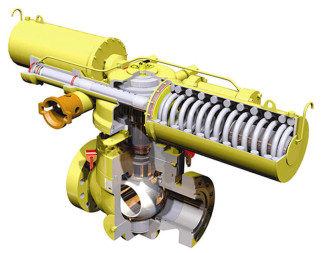 Figure 6 Subsea valve with hydraulic actuator. (Source: Offshore Technology website)
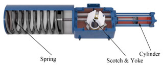 Figure 7 Quarter-turn hydraulic actuators (Source: Schlumberger website)
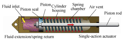 Figure 8 Linear hydraulic actuator (Source: Machine Design website)
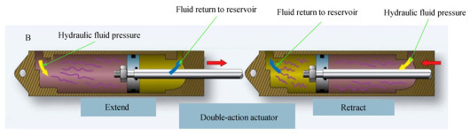 Figure 9 Double-acting hydraulic actuator (Source: Machine Design website)
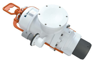 Figure 10 Subsea electric actuator (Courtesy: Aker Solutions)
A subsea electric actuator includes an electrical motor and a connection from the motor to a drive unit, which can be moved forward and back to convert rotary motion to linear motion of the actuator stem and overcome the spring force (Pishock 2016; Joyee 2015). This type of actuator has mechanical spring and fail-safe action, which means that the valve is closed or opened by a spring force in case of a failure, such as electric actuator motor collapse. Electric actuators without spring have an FAI failure mode to stay in position.
To summarize, the features and differences between hydraulic and electric actuators are given in Table 2.
Table 2 Hydraulic and electrical actuators comparisionFeatures and differences Electric actuator Hydraulic actuator Energy consumption Electrical power, which is lower compared with hydraulic Hydraulic oil Environmentally friendly More environmentally friendly Less environmentally friendly Space consumption More compact Less compact Risk of leakage No Yes Fail-Safe option Yes, through using spring and loss of power Yes, through using spring and loss of hydraulic Reliability More Less Flexibility in usage in different locations Yes Yes 5 Subsea Manifold Valves
The reliability of subsea manifolds is largely dependent on subsea valves. Ball and Through Conduit Gate (TCG) valves are typically used in the manifolds for on/off purposes (Bai and Bai 2012; Praveen et al. 2018). TCG valves have a long history of application for both manifolds and trees (Bai and Bai 2012). Choke valves may be used for flow regulation in a manifold or a tree (Bai and Bai 2012; Praveen et al. 2018). In addition, small size check valves are selected for trees to prevent backflow in chemical injection lines. One philosophy for subsea valve selection for on/off purposes is to use TCG valves for pipe sizes up to and including 8″ or 10″ and ball valves for the larger sizes (Bai and Bai 2012; Praveen et al. 2018). TCG valves are more robust than metal-seated ball valves in terms of sealing and operation in "dirty" subsea service; fluids with suspended solids can seriously impair the performance of the valve unless the correct valve type and trim (valve internals) are selected (API 2016).
The sealing surface required to prevent valve leakage is achieved between flat faces of the gate and two seats in through the TCG valve, as shown in Figure 11. Sealing between two flat faces is more reliable than sealing between spherical surfaces of the seats and the ball in a ball valve (Figure 12). TCG valves provide sealing of metal to metal, and metal-seated ball valves are popular choices for subsea applications. Thus, the sealing between the ball and seat in metal-seated ball valves is a metal to metal seal, similar to TCG valves. However, the metal-seated ball valve is not as robust as a TCG valve, because ball valves' seats cannot cope with solid objects and may become damaged during operation.
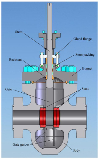 Figure 11 TCG valve (slab type) (Courtesy: Orion Valve)
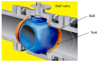 Figure 12 Ball valve
6 Gap in Literatures
One of the gaps in existing reviewed literature in this paper is the effect of using all-electric actuators for manifold valves. There are three main questions related to this gap listed below:
1 What types of electric actuators are required for manifold valves between two choices of spring return and traditional one?
2 Are the electric actuators subject to safety integrity level (SIL) and subsequent certification?
3 Can introducing electric actuators change the valve selection philosophy given that ball valves may require less electrical energy for operation compared with conduit gate valves?
7 Data Gathering and Analysis
Forty hydraulic-actuated manifold valves from nine past subsea projects in different parts of the world, mainly from Africa and Australia, have been selected for the analysis of all electric actuators. The selected valves are either slab gate or ball valve in size ranges from ¾" to 18″ and pressure classes from 5000 to 10 000 psi. Twenty-nine valves out of 40 are fail-safe close (FSC), whereas eight valves have fail-safe open (FSO) function. The other important finding is that almost all the gate valves are normally open with FSC function, whereas ball valves are either FSC or FSO. One gate and two ball valves have double-acting hydraulic actuators with FAI function. The results of the analysis and type of electric actuators are summarized in Table 3. Notably, spring-return electric actuators and traditional non-spring-return electric actuators are proposed for fail-safe and FAI actuators' functions, respectively.
Table 3 Summery of analysis of manifold valve electrical actuatorManifold valve electric actuators FSC FSO FAIL-AS-IS Slab gate valve 22 1 1 Ball valve 7 7 2 Total numbers 29 8 3 Proposed electric actuators Spring return Spring return Non-spring-return 8 Actuated Valves on Subsea Manifolds (Ball/Gate), Size ¾"to18, " Pressure from 5000 to 10 000 psi
The analysis shows that 37 spring-return and 3 non-spring-return electric actuators are required for 40 valves in this case study. Approximately 93% of the valves should be equipped with spring-return actuators, and 7% with traditional motor-operated electric actuators do not have any spring.
SIL is a part of an international standard, such as IEC 61508, that provides suppliers and end users with a common framework to design products and systems with electrical components for safety-related applications (ESI Technologies Group 2019; Sotoodeh 2019). SIL provides a scientific and numerical approach to specifying and designing safety systems and enabling risk of failure to be qualified applications (ESI Technologies Group 2019; Sotoodeh 2019). In simple terms, SIL is a numerical measurement of performance required for safety instrumented function (Sotoodeh 2019; Wikipedia 2019). IEC 61508 is an international standard published by the International Electrotechnical Commission addressing the functional safety of electrical and electronic safety-related systems (Sotoodeh 2019; IEC 61508, 2010). Actuated valves with safety functions such as emergency shut down valves and those connected to process safety systems should be SIL certified according to the offshore industry practices (Sotoodeh 2019). Manifold valves do not have any safety function, so they are not subject to SIL certification (Norwegian Oil and Gas Association 2018). SIL certificate means achieving high reliability and environmental friendliness of the actuated valves. However, high reliability of the manifold valves is achieved through more serious testing such as qualification and factory acceptance tests, accurate tolerance during production, and corrosion resistance material selection in most cases. Additionally, using FSC actuated valves in most cases, which can lead to shutting down the valves in the event of failure, is a good safety measure.
Two problems can arise when changing the smaller size TCG to ball valves to reduce power consumption. The first one is design validation implementation through finite element analysis and tests (API 2017; API 2018; API 2011; ISO 2010a, 2010b; ISO 14723, 2009). Design changes, such as valve type and configuration, body style, type of sealing, design of sealing, and size change of drive train, require design validation, which is costly and time-consuming (API, 2019; ISO 14723, 2009). The second issue is related to the operation of small ball valves instead of through the conduit gate in particle-containing services. As previously described, TCG valves are more robust than metal-seated ball valves in terms of sealing and operation in "dirty" subsea service; fluids with suspended solids may seriously impair the performance of the valve unless the correct valve type and trim (valve internals) are selected (API 2016). Thus, the valve selection philosophy for manifold valves should not be changed to avoid possible valve damage and undesirable maintenance. One advanced and new technology is to use electrohydraulic actuators to reduce the power consumption (Orth and Hendrix 2018). This technology combines the advantages of both electric and hydraulic actuator technologies. The electric power is provided centrally and converts the energy to the actuator power stands as close as possible. Hydraulic pipes and tubes are not necessary in this technology (Orth and Hendrix 2018).
9 Conclusions
Subsea development is moving constantly toward simplification, digitalization, and cost-out strategies because the exploration and production of hydrocarbons are gearing toward deeper and remote sea water areas. Usage of all-electric subsea technology instead of hydraulic technology is constantly growing and will be the future of subsea systems due to the former's environmental and functional advantages and reduced costs. The all-electric control system eliminates the need for traditional hydraulic control systems. The benefits of all-electric subsea systems are HSE, reduced costs, and improved reliability, flexibility, and functionality compared with traditional hydraulic–electric systems. Existing EHT for a typical subsea system, hydraulic and electric actuators, and subsea manifold valves including valve types and selection philosophy have been reviewed in this paper. One of the gaps in existing reviewed literatures in this paper is the effect of using all-electric actuators for the manifold valves. Forty hydraulic-actuated manifold valves from nine past subsea projects in different parts of the world, mainly from Africa and Australia, have been selected for the analysis of all-electric actuators. Three main questions have been addressed for manifold valves: SIL certification, type of electric actuators, and possibility of changing the valve selection philosophy to the all-electric control system eliminate the need for traditional hydraulic control systems. The benefits of all-electric subsea systems are HSE, reduced costs, and improved reliability, flexibility, and functionality compared with traditional hydraulic–electric systems. Existing EHT for a typical subsea system, hydraulic and electric actuators, and subsea manifold valves including valve types and selection philosophy has been reviewed in this paper. One of the gaps in existing reviewed literatures in this paper is the effect of using all-electric actuators for the manifold valves. Forty hydraulic-actuated manifold valves from nine past subsea projects in different parts of the world, mainly from Africa and Australia, have been selected for the analysis of all-electric actuators. Three main questions have been addressed for manifold valves: SIL certification, type of electric actuators, and possibility of changing the valve selection philosophy to reduce the electricity consumption. SIL is not relevant to manifold valves, and spring-return electric actuators should be used for more than 90% of the actuated valves. The selection of spring-return actuators does not require an SIL certificate. Additionally, it is not recommended to change the valve selection philosophy for the manifolds to achieve lowered electricity power consumption mainly due to the cost and time associated with new design validation through FEA and qualification tests. A relatively new electrohydraulic actuator technology has been developed with low power consumption. Another research is proposed for further investigation about this new technology (Orth and Hendrix 2018).
Acknowledgments: I would like to express my gratitude to my partner, Ms. Tamara Zhunussova, for her great support. -
Figure 1 Typical subsea production system (Courtesy: Elsevier)
Figure 2 Subsea manifold (Courtesy: Subsea Enginerring Handbook)
Figure 3 Subsea umbilical (Source: Aker Solutions website)
Figure 4 Subsea control for topside and subsea (Source: Subsea Engineering Handbook)
Figure 5 Electrohydraulic control system (Source: Subsea Engineering Handbook)
Figure 6 Subsea valve with hydraulic actuator. (Source: Offshore Technology website)
Figure 7 Quarter-turn hydraulic actuators (Source: Schlumberger website)
Figure 8 Linear hydraulic actuator (Source: Machine Design website)
Figure 9 Double-acting hydraulic actuator (Source: Machine Design website)
Figure 10 Subsea electric actuator (Courtesy: Aker Solutions)
Figure 11 TCG valve (slab type) (Courtesy: Orion Valve)
Figure 12 Ball valve
Table 1 AET and EHT reliability comparision (Theobald 2005)
Production percentage Number of active wells AET availability percentage EHT availability percentage 100 4 86.5 84.3 > 75 3 or 4 96.9 96.4 > 50 2 or 3 or 4 97.5 97.0 > 25 1 or 2 or 3 or 4 97.5 97.0 Table 2 Hydraulic and electrical actuators comparision
Features and differences Electric actuator Hydraulic actuator Energy consumption Electrical power, which is lower compared with hydraulic Hydraulic oil Environmentally friendly More environmentally friendly Less environmentally friendly Space consumption More compact Less compact Risk of leakage No Yes Fail-Safe option Yes, through using spring and loss of power Yes, through using spring and loss of hydraulic Reliability More Less Flexibility in usage in different locations Yes Yes Table 3 Summery of analysis of manifold valve electrical actuator
Manifold valve electric actuators FSC FSO FAIL-AS-IS Slab gate valve 22 1 1 Ball valve 7 7 2 Total numbers 29 8 3 Proposed electric actuators Spring return Spring return Non-spring-return -
Abicht D, Halvorsen GR (2017) Subsea all-electric. Offshore Technology Conference, Houston API (2011) Design and operation of subsea production systems, subsea wellhead and tree equipment. 2nd edition, American petroleum institute (API) 17D, Washington, DC API (2016) Valve selection guide. 2nd edition, American petroleum institute (API) 615, Washington, DC API (2017) Specification for subsea pipeline valves. 3rd edition, American petroleum institute (API) 6DSS, Washington, DC API (2018) Specification for wellhead and tree equipment. 21st edition, American petroleum institute (API) 6A, Washington, DC Bai Y, Bai Q (2012) Subsea engineering handbook, 1st edn. Elsevier, Atlanta ESI Technologies Group (2019) SIL certificate ball valves and actuators: a brief review of SIL. Available from: https://esitechgroup.com/blog/sil-certified-ball-valves/. Accessed 10th of Jul 2019 Gonzalez C (2015) What is the difference between pneumatic, hydraulic and electrical actuators? Machine Design. Available from: https://www.machinedesign.com/linear-motion/what-s-difference-between-pneumatic-hydraulic-and-electrical-actuators. Accessed 10th of Jul 2019 International Electrotechnical Commission (2010) Functional safety of electronic / programmable electronic safety-related systems, Part Ⅰ: General requirements, 2nd edition, IEC 61508, Genova ISO (2009) Petroleum and natural gas industries-pipeline transportation systems- subsea pipeline valves. 2nd edition, International Organization for Standardization (ISO) 14723, Geneva ISO (2010a) Petroleum and natural gas industries-design and operation of subsea protection systems. Part 4: Subsea wellhead and tree equipment. 2nd edition, International Organization for Standardization (ISO) 13628–4, Geneva ISO (2010b) Petroleum and natural gas industries-drilling and production-wellhead and christmas equipment. 4th edition, International Organization for Standardization (ISO) 10423, Geneva Joyee W (2015) Subsea electrical actuators and latches for them. Aker Subsea, Aberdeen, UK Larsen EW, Massie D, Eriksson KG (2016) Subsea all-electric technology: enabling next generation field developments. Offshore technology conference, Houston OTC-27243-MS Norwegian Oil and Gas Association (2018) Application of IEC 61508 & 61511 in the Norwegian petroleum industry (recommended SIL requirements). Revision 3 One Subsea, A Schlumberger Company (2019) All-electrical technologies. Retrieved from: https://www.onesubsea.slb.com/control-systems/all-electric. Accessed 10th of Jul 2019 Orth A, Hendrix G (2018) An electro-mechanical actuator with hydrostatic drive for subsea trees to reduce CAPEX and OPEX with higher reliability and safety levels. Offshore Technology Conference, OTC-28828-MS. Pishock D (2016) Choosing between a double acting and spring return actuator. Available from: https://valveman.com/blog/double-acting-vs-spring-return-actuators/. Accessed 10th of Jul 2019 Praveen J, Pathan M, Ansari K (2018) Hyperbaric pressure testing of a subsea valve to validate deep water condition. International Journal of Mechanical and Production Engineering Research and Development 8(2): 1011–1022 Schlumberger Company (2018). LEDEEN hydraulic actuators and controls. Available from: https://www.products.slb.com/valves/brands/ledeen/ledeen-hydraulic-actuators. Accessed 10th of Jul 2019 Society for Underwater Technology (2008) Subsea production control. SUT, Subsea awareness course Sotoodeh K (2019) Safety integrity level in valves. J Fail Anal Prev 18(3): 832–837. https://doi.org/10.1007/s11668-019-00666-2 Theobald M (2005) Benefits of all-electric subsea production control systems. British Petroleum, Offshore Technology Conference, Houston Wikipedia (2019) Safety integrity level. Available from: https://en.wikipedia.org/wiki/Safety_integrity_level. Accessed 10th of Jul 2019