Circulation-Enhanced Tank Heating Using Shallow Profile Coil Bundles
https://doi.org/10.1007/s11804-020-00149-z
-
Abstract
Heavy fuel oils require heated tanks to facilitate their transportation and processing. This paper proposes and investigates three- and four-level heating coil bundles. Numerical study revealed that powerful large-scale circulation of the heated fluid enhances heat transfer, delivering 16.7% and 23% improvements to the average heat transfer coefficient for the three- and four-level bundles, respectively. Furthermore, this circulation improves oil mixing and limits the variation in bulk oil temperature to −0.3 to +1.3 ℃ from the average. The study also quantified oil flow velocity near the bottom of the tank. The time-averaged horizontal components of velocity, estimated 25 mm and 50 mm above the bottom of the tank, exceed 2 mm/s and 4 mm/s, respectively. The proposed heating coil bundles feature a compact design that reduces the material and labor costs of construction and that, by occupying only a small portion of the bottom of the tank, improves accessibility, maintenance, and cleaning.-
Keywords:
- Heating coil ·
- Tank heating ·
- Bundle ·
- Convection ·
- Large-scale circulation
Article Highlights• Buoyancy-generated large-scale cargo circulation enhances the heat transfer.• Compact heating coil bundles reduce material, installation, and maintenance costs.• The oil flow structure mainly determines the heating process effectiveness. -
1 Introduction
Heavy fuel oils, as well as other viscous oils and chemicals, require heated tanks to improve their transportation and processing. Several concepts and various equipment for tank heating have been proposed and implemented.
Zolling (1914) and Matthews (1962) proposed using uniformly distributed heating coils extended closely above the bottom of the tank, a concept today known as the conventional tank heating solution. Different approaches utilizing heat exchangers were proposed by Mohn (1969) and Bridan (1979). Nakamoto and Takeshita (1981) introduced the concept of multilevel heating coil bundles situated between the tank's longitudinal and transverse structural elements. Much more recently, Okano (2011) proposed a heating coil arrangement that occupies only part of the bottom of the tank, leaving the rest of the area free for working vehicle use. To heat a fuel oil tank, one new concept utilizes heating drums (Shin et al. 2015; Kang and Kang 2016). Guo 2017 proposed arranging heating coils in the form of prismatic towers, Guo et al. (2017) introduced microwave heaters, and Magazinović (2018a, b, 2019) re-established the concept of multilevel heating coil bundle.
A basic calculation procedure for tank heating was given by Magazinović (1987), who compiled the works of van der Heeden and Mulder (1965), Couchman et al. (1966), Saunders (1968), Akagi (1969), Suhara (1970), and Kurihara et al. (1972). An important treatment for high-viscosity fuel and crude oil heating was provided in Akagi et al. (1985), while Akagi and Kato (1987) investigated the impact of vessel rolling on tank heating. Finally, the results of numerical simulations were presented by Akagi et al. (1986) and Pivac and Magazinović (2015).
The subject of natural convection in an enclosure has diverse industrial applications and, hence, has seen active investigation (Baïri et al. 2014). Warrington and Crupper (1981) experimentally studied natural convection heat transfer between cylindrical tube bundles and a cubical enclosure.
Concerning onshore oil storage, Yang et al. (2018) performed experimental research on a circular oil tank, calculating the total heat transfer coefficient of the tank under various working conditions. Mathematical modeling of temperature fields of fuel oil within a rectangular storage tank was performed by Kuznetsova (2015) assuming a constant temperature heat source at the bottom of the tank. Zhao et al. (2017) revealed that the plume induced by natural convection is the most influential factor for the formation of the temperature field in the tank. For a circular storage tank, Sun et al. (2018) found that a serpentine-structured coil heats the fastest and more stable than vertical- or stereoscopic-structured coils.
Large-scale circulation of a fluid is a rolling motion the scale of which is comparable with the size of the container itself (Xi et al. 2006; Sreenivasan et al. 2002). Although large-scale circulation may be generated solely by convective heat flux at the vessel boundary (Krishnamurti and Howard 1981; Sitarski et al. 2013), it can also be produced by an asymmetrically positioned heat source within the container (Magazinović 2018b). The latter property is instrumental in the present work, where large-scale circulation boosts fluid flow around the heating coils, thus improving the heat transfer mechanism from the less effective natural convection to the more effective mixed convection.
The present study aims to quantify the thermal performance of shallow profile heating coil bundles, asymmetrically situated close to the middle at the bottom of the tank. Two types of compact size, shallow profile heating coil bundles are investigated: three- and four-level.
The remainder of this paper is organized as follows. Section 2 defines the technical problem of tank heating by shallow profile heating coil bundles. Section 3 describes a numerical setup for testing the proposed heating equipment, with simulation results provided in Section 4. Section 5 discusses two items worth further investigation, and Section 6 concludes.
2 Problem Formulation
Traditionally, heating coils are one- or two-level grids of tubing evenly extended over the bottom of the tank. Such an arrangement seems reasonable under the assumptions of a natural, convective heat transfer mechanism and mostly negligible heated fluid flow. However, given the large-scale circulation of the heated fluid, such an arrangement proves far from ideal. During large-scale circulation, the rolling fluid has its maximum velocity at a significant distance from the tank walls, especially from the bottom of the tank. Furthermore, due to the circularly shaped streamlines developed within the rectangular cavity (see, e.g., Khanafer et al. 2003), the velocity profiles in the tank corners are largely depressed. Consequently, the narrow area above the middle of the tank's bottom is the most favorable location to use the velocity profile of large-scale circulation to increase the thermal effectiveness of heating coils.
2.1 Shallow Profile Heating Coil Bundles
This study proposes and analyzes two types of shallow profile heating coil bundles. Figure 1 depicts the proposed three- and four-level heating coil bundles. Both share the same design intent, characterized by the use of there are 20 tubes, each six meters long, 50A size, straight steel heating tubes in a 400 mm horizontal and 200 mm vertical matrix-like pattern, with the first tube level at 150 mm height. The overall breadth and height of the proposed three- and four-level bundles are then 2460 mm by 580 mm and 1660 mm by 780 mm, respectively, providing a total heating coil length, in both cases, slightly greater than 131 m.
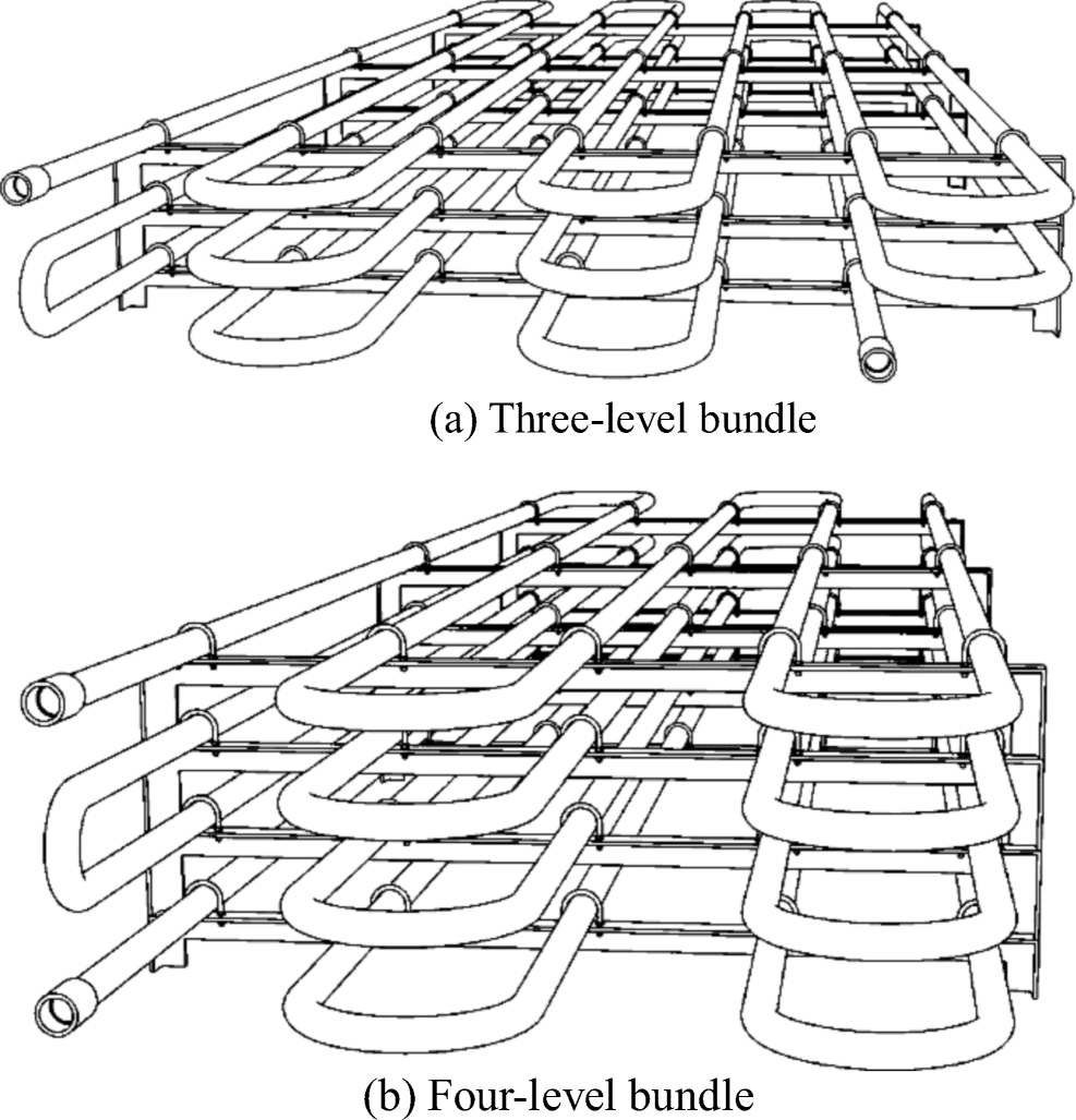 Figure 1 Studied shallow profile heating coil bundles
While the three-level heating coil bundle somewhat resembles the conventional two-layer arrangement, the four-layer bundle significantly departs from the conventional arrangement.
A real, previously analyzed, tank heating problem is selected as a basis for numerical evaluation (Magazinović 2018a).
2.2 Tank Heating Problem
The sample tank (Figure 2) has 17.5 m breadth, 16.8 m height, 26.4 m length, and a 15.4 m filling level, providing a cargo hold of 7360 m3 at full capacity.
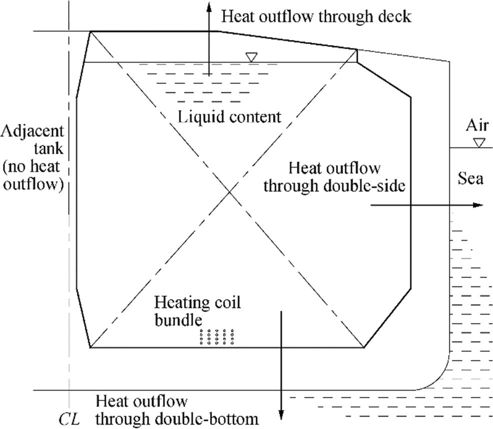 Figure 2 Tank heating model used in this study
A cold environment is defined by 2 ℃ air and 5 ℃ sea temperatures. The cargo content at 55 ℃ is subjected to convective heat outflows at the outer tank boundary, which comprises a deck, a double-side, and a double-bottom. The respective heat transfer coefficients are assumed as defined in Jandrijević et al. (2007). The remaining tank boundary, including the longitudinal and two transverse bulkheads, is assumed to be thermally neutral and without heat exchange.
Standard RMH-45 heavy fuel oil is selected as a sample heated fluid. Table 1 lists the typical thermophysical properties of this fluid.
Table 1 Fuel oil properties at two characteristic temperatures (Magazinović 2018a)Temperature (℃) 55 157 Model Density (kg/m3) 964 893 linear Dynamic viscosity (Pas) 0.405 0.009 Eq. (1) Thermal conductivity (W/mK) 0.130 0.106 linear Specific heat capacity (J/kgK) 1870 2260 linear While density, thermal conductivity, and specific heat capacity depend linearly on temperature, the dynamic viscosity change is highly nonlinear. Therefore, for temperatures besides those in Table 1, a seventh-degree polynomial approximation may be used:
$$ {\displaystyle \begin{array}{l}\mu =6800.738-87.7857\cdot T+0.4216867\cdot {T}^2\\ {}-7.63075\mathrm{E}\hbox{-} 04\cdot {T}^3-5.88163\mathrm{E}\hbox{-} 7\cdot {T}^4\\ {}+4.628609\mathrm{E}\hbox{-} 9\cdot {T}^5-6.968834\mathrm{E}\hbox{-} 12\cdot {T}^6\\ {}+3.591825\mathrm{E}\hbox{-} 15\cdot {T}^7,\end{array}} $$ (1) where μ is the dynamic viscosity and T is the absolute oil temperature. Equation (1) is obtained by a polynomial regression of the data provided in Anon (2014).
For cargo heating, 8-bar steam is assumed, providing a heat source at a temperature of 170.4 ℃. Furthermore, applying a heat conduction equation and assuming coil thermal conductivity of 59 W/mK and fouling resistance of 5 × 10⁻⁴ m2K/W, a lower mean coil surface temperature of 157 ℃ is defined. Finally, as Kurihara et al. (1972) measured, a linear temperature change of ± 7.5 ℃ between the top and bottom surfaces of the coil is assumed (Figure 3).
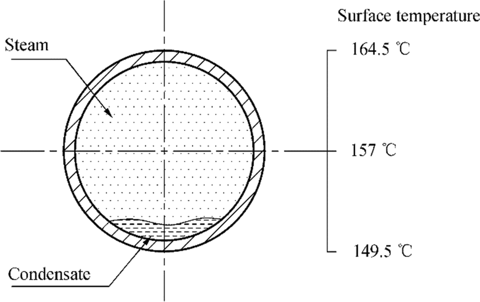 Figure 3 Coil surface temperature distribution
To heat the cargo, a set of three equal heating coil bundles is extended in a row along the tank length, parallel to the tanker's longitudinal plane of symmetry. The three- and four-level bundles are offset against that plane by 7.15 and 6.76 m, respectively.
Additional problem considerations are summarized as follows. Since cargo heating is an intrinsically unsteady process during which cargo density changes with time, proper analysis must be transient and compressible. The fluid flow around the heating coils is also laminar, as documented in Magazinović (2019). Finally, although the technical problem at hand is three-dimensional, it may be treated as two-dimensional due to the prohibitive computational costs associated with a three-dimensional problem. However, it should be noted that the tank's horizontal and vertical aspect ratios of 1.5 and 1.7, respectively, are close to, but still below, the minimum value of 1.8 recommended by Corzo et al. (2011). Therefore, the drawbacks and limitations (e.g., lower fidelity and accuracy) of such a simplification should be kept in mind.
The problem defined herein is analyzed twice, once each for three- and four-layer heating coil bundles. The expected results comprise estimations of the time-averaged heat transfer coefficients, cargo temperature variations, and changes in cargo flow velocity, with emphasis on fluid flow in the bottom area of the tank.
3 Numerical Solution
The tank heating problem, as defined above, may be solved numerically by many available computational fluid dynamics (CFD) techniques (Bhutta et al. 2012). In that regard, an open-source set of numerical tools, OpenFOAM (Greenshields 2015; Moukalled et al. 2016), offers a viable approach. Besides being widely accepted technology with proven accuracy (Corzo et al. 2011), OpenFOAM features very compelling license terms.
3.1 Governing Equations
The theoretical foundation of the problem may be summarized in a set of governing equations, comprising a mass conservation equation
$$ \frac{\partial \rho }{\partial t}+\nabla \cdot \left(\rho \boldsymbol{U}\right)=0, $$ (2) where U is the velocity vector, ρ is the density, and t is time; a momentum conservation equation
$$ {\displaystyle \begin{array}{l}\frac{\partial \left(\rho \boldsymbol{U}\right)}{\partial t}+\nabla \cdot \left(\rho \boldsymbol{U}\boldsymbol{U}\right)=\\ {}\nabla \cdot \left\{{\mu}_{\mathrm{eff}}\left[\nabla \boldsymbol{U}+{\left(\nabla \boldsymbol{U}\right)}^T\right]\right\}-\nabla \left[\frac{2}{3}{\mu}_{\mathrm{eff}}\left(\nabla \cdot \boldsymbol{U}\right)\right]-\nabla p+\rho \boldsymbol{g},\end{array}} $$ (3) where p is the static pressure, g is the gravitational acceleration vector, and μeff is the effective viscosity; and finally an energy conservation equation
$$ {\displaystyle \begin{array}{l}\frac{\partial \left(\rho h\right)}{\partial t}+\nabla \cdot \left(\rho \boldsymbol{U}h\right)+\frac{\partial \left(\rho K\right)}{\partial t}+\nabla \cdot \left(\rho \boldsymbol{U}K\right)-\frac{\partial p}{\partial t}=\\ {}\nabla \cdot \left({\alpha}_{\mathrm{eff}}\nabla h\right)+\rho \boldsymbol{U}\cdot \boldsymbol{g},\end{array}} $$ (4) where K is the kinetic energy, αeff is the effective thermal diffusivity, and h is the enthalpy.
Since Eqs. (2), (3), and (4) are provided in vector form, for a two-dimensional problem, they comprise a full set of five equations and five unknowns, namely, fluid pressure, density, enthalpy, and two velocity components. Enthalpy enables determination of fluid temperature, and the temperature gradients form the basis for the boundary heat flux calculations.
3.2 Mesh
Spatial discretization of the computational domain is an important step towards obtaining a numerical solution. Two computational meshes, each with 183 586 and 183 170 cells, are generated to cover the three- and four-level heating coil bundles, respectively. Special attention is paid to the boundary of the heating coil; that is discretized by 27 layers, each comprising 120 cells, and the first layer is 0.05 mm thick (Magazinović 2019).
3.3 Initial and Boundary Conditions
Both analyses start (at t = 0 s) from the same set of initial conditions, defined throughout the computational domain by a cargo temperature of 55 ℃, static pressure of 101 325 Pa, and zero oil velocity.
The boundary conditions of the heating coil are defined by calculated hydrostatic pressure, zero velocity, and surface temperature, as given in Figure 3.
The double-bottom, double-side, and longitudinal bulkhead of the tank share the same pressure and velocity boundary conditions, set throughout as calculated hydrostatic pressure and zero velocity, respectively. However, each differs in how the temperature boundary condition is treated. While the longitudinal bulkhead fulfills a zero gradient condition, the double-bottom and double-side boundaries are subjected to convective heat outflows defined by respective overall heat transfer coefficients. According to Jandrijević et al. (2007), the double-bottom heat transfer coefficient is 3.2 W/m2K, while 3.3 W/m2K is appropriate for the outer tank wall.
The top tank boundary, represented by an oil filling level, behaves differently compared with the preceding boundaries since it is open to the atmosphere. Here, the pressure boundary condition is calculated from zero total pressure and local velocity; the velocity boundary condition should permit both outflow and inflow (Greenshields 2015). Hence, a zero gradient condition is applied to all velocity components, except where there is an inflow, in which case a fixed value condition is applied to the tangential component. Concerning temperature, the same boundary condition applies as in the case of the tank's double-bottom.
The mathematical form of these boundary conditions may be found in Magazinović (2019).
3.4 Solver Settings
For numerical simulations, the OpenFOAM version 3.0 toolbox (Greenshields 2015) was selected. A buoyantPimpleFoam solver, backed by the swak4Foam, wallHeatFlux, and paraView utilities, was used to generate and process the results provided herein.
buoyantPimpleFoam is a segregated, transient solver for compressible fluid flows that combines the Piso and Simple algorithms (Moukalled et al. 2016) in a time-stepping manner.
At each time step, the algorithm solves Eqs. (2), (3), and (4) until a general tolerance of 10−4 is met, updates the result list, and prepares the data sets for the next time step. The magnitude of the time step, determined by a Courant number criterion, is set to 0.5.
To enhance the time-stepping progress, some additional parameters are set. At each time step, up to five Pimple iterations are allowed, further stabilized by two corrector iterations and two nonorthogonal corrector iterations. The solver tolerance of the pressure equation is set to 10−8, while the remaining solvers use more relaxed criteria of 10−6. A process of results under-relaxation is also included, applying a 0.3 factor for pressure and 0.7 factors for momentum and energy.
Internally, the applied discretization schemes are as follows. The gradients use a default Gauss linear scheme, while a corrected scheme is applied for the component of gradients normal to a cell face. For the diffusion term, a Gauss linear corrected scheme is selected. The advection terms utilize Gauss vanLeer (for kinetic energy and enthalpy) and Gauss vanLeerV (for velocity) schemes. Finally, a Gauss linear scheme is applied to the non-advection term, while a first-order implicit Euler scheme is selected for the temporal discretization.
4 Results
Two numerical simulations were executed, one each for the three- and four-level bundles (Figures 4 and 5, respectively) and both covering 3-h heating duration. Simulations took around 13 and 15 days to complete, respectively, run on six cores of a dual 3.06 GHz processor Linux workstation.
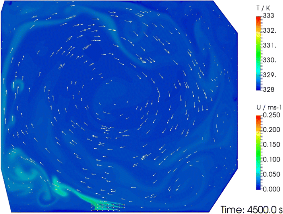 Figure 4 Tank cross-section indicating large-scale circulation generated by a three-level bundle
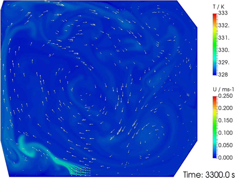 Figure 5 Tank cross-section indicating large-scale circulation generated by a four-level bundle
4.1 Coil Heat Transfer Coefficient
Results for the coil surface convective heat transfer coefficients (Figures 6 and 7) clearly indicate two distinct heat transfer mechanisms. The first, natural convection, exists during the initial, pre-circulation phase. The second mechanism, mixed convection, arises after around 2000 s of heating during the large-scale circulation phase. Roughly, the first phase ends at t = 1800 s, while the second phase fully develops at t = 2700 s. For the time period in between, the heat transfer mechanism may be considered in transition.
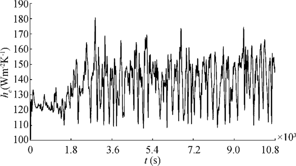 Figure 6 Coil heat transfer coefficient, three-level bundle
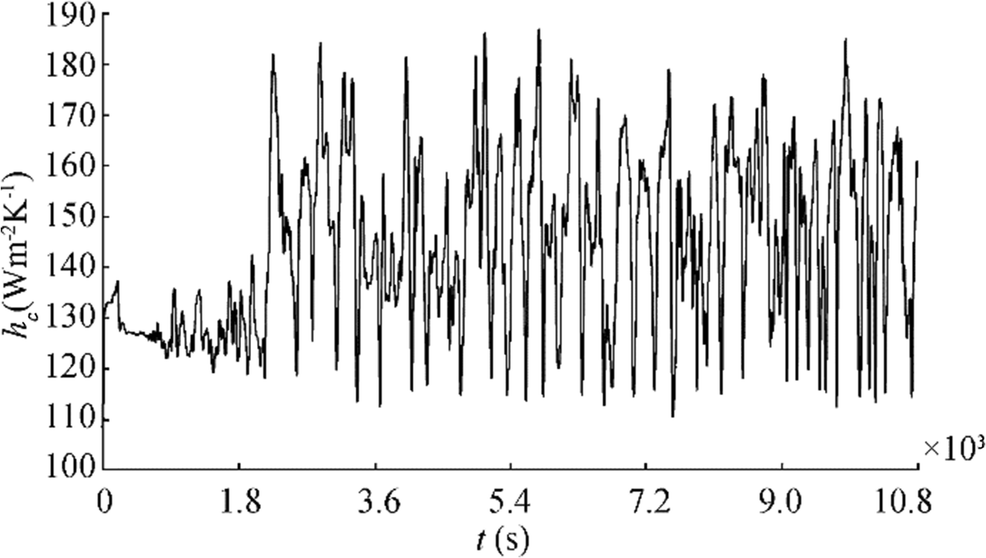 Figure 7 Coil heat transfer coefficient, four-level bundle
The natural convection phase is characterized by high frequency, low amplitude variation in the heat transfer coefficient, whereas the mixed convection phase lowers the frequency but stretches the amplitudes of the variations in the heat transfer coefficient.
On a time-averaged basis, considering all 20 heating coils as one, during the initial 1800 s of heating, the natural convection phase generates a heat transfer coefficient of 123.5 W/m2K in the case of the three-level bundle and 127.3 W/m2K in the case of the four-level bundle.
Notably, a classic estimate of the coil heat transfer coefficient (Akagi 1969) is 116.2 W/m2K. The differences of + 7.3 W/m2K (+ 6.3%) and + 11.1 W/m2K (+ 9.6%) for the three- and four-level bundles, respectively, may be attributed to the influence of the number of coil levels. While the present study deals with three and four tubes arranged each above the other, the Akagi result relates only to a single tube.
Concerning the large-scale circulation phase, when the mixed convection heat transfer mechanism prevails, the heat transfer coefficient values time-averaged to 140.3 W/m2K and 147.9 W/m2K for the three- and four-level heating coil bundles, respectively. Compared with their pre-circulation estimates, a 13.6% improvement in the circulation heat transfer coefficients is achieved for the three-level bundle case, while the four-level bundle case delivers a 16.2% improvement. Given a conventional heating coil arrangement as a baseline design (heat transfer coefficient estimated at 120.2 W/m2K; Magazinović 2018a), the preceding indicators of improvement rise to 16.7% and 23.0%, respectively.
Compared with the eight-level bundle result of 199.2 W/m2K (Magazinović 2019), the present values of the time-averaged heat transfer coefficient are significantly lower. Three factors are responsible for this divergence. Firstly, in the present case, the simulation uses a fuel oil of higher viscosity. Secondly, in the shallow profile heating coil bundles, the tubes are situated closer to the bottom of the tank, where the velocity of oil circulation is generally low (Figs. 4 and 5). Finally, the heating tubes in the shallow profile bundle are arranged in an increased number of heating coil columns, further reducing the cross-flow velocity and the corresponding heat flux.
4.2 Estimate of Mesh Discretization Error
For the three-level bundle case, two additional meshes were generated, each with 114 083 and 72 620 cells. The corresponding average heat transfer coefficients were 135.9 W/m2K and 133.1 W/m2K, respectively.
Applying the procedure of Celik et al. (2008), the following error estimates are obtained: approximate relative error 3.1%, extrapolated relative error 6.3%, fine-grid convergence index 8.4%, and apparent order 1.61.
4.3 Oil Velocity
In the course of the simulations, two indicators of oil velocity were recorded (Figures 8 and 9). The full line denotes peak velocity, recorded anywhere within the calculation domain, whereas the dashed line expresses the area-averaged velocity, covering the entire domain at once.
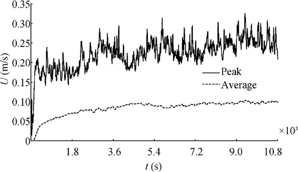 Figure 8 Oil velocity, three-level bundle
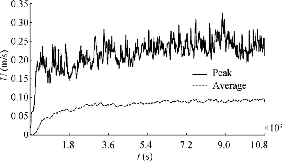 Figure 9 Oil velocity, four-level bundle
Initially, both indicators steeply rise. Fluid acceleration then gradually fades. Assuming acceleration vanishes at t = 9000 s, the velocity indicators for the remaining heating period are time-averaged in Table 2. The slightly lower indicators encountered in the case of the four-level bundle could be attributed to the greater adverse effect its greater height of 780 mm exercises on the structure of the circulation flow. The three-level bundle, which has a height of 580 mm, is less constricting to the oil flow.
Table 2 Oil velocity time-averaged indicators for t > 9000 sIndicator (m/s) Three-level bundle Four-level bundle Peak velocity 0.258 0.237 Average velocity 0.098 0.093 The velocity results presented here are comparable with the velocity indicators shown in the eight-level bundle case (Magazinović 2019). The slightly lower readings in Figures 8 and 9 may be attributed to the higher oil viscosity used in the present study.
Significantly lower velocity readings were reported by Sun et al. (2018) and Zhao et al. (2017); their peak velocity reached 0.13 m/s and 0.121 m/s, respectively. The divergence may be attributed to differences in the sizes of heat source. While the present study involves 20 heating coils, the two referenced works respectively involve four and five coils.
4.4 Oil Temperature
Globally, change in oil temperature indicates the difference between heat inflow and outflow. Whereas heat inflow is provided by the heating coils (Section 4.1), heat outflow is governed by convective heat transfer at the tank boundary (Table 3).
Table 3 Heat outflow at tank boundaryBoundary (kW) Three-level bundle Four-level bundle Deck 59.2 59.2 Double-side 56.8 56.7 Double-bottom 39.7 38.8 Total 155.7 154.8 Assuming average heat transfer coefficients as reported in Section 4.1, a set of three heating coil bundles jointly produces heat inflow around 1100 kW. Of that quantity, some 14% is spent reclaiming heat outflows (Table 3), whereas the remaining 86% is directed towards raising the oil temperature (Figures 10 and 11).
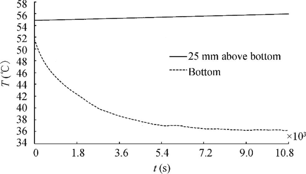 Figure 10 Oil temperature, three-level bundle
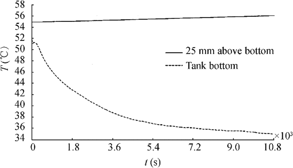 Figure 11 Oil temperature, four-level bundle
The global rise in oil temperature is represented by solid lines in Figures 10 and 11 for the three- and four-level bundle cases, respectively. During the 3-h heating period, the oil temperature, area-averaged 25 mm above the bottom of the tank, steadily rises by 1.09 ℃ and 1.13 ℃, respectively, reflecting the higher energy gain provided by the four-level bundle. However, it should be noted that both readings are higher than the actual rises in temperature. The discrepancy results from using a two-dimensional approximation of a three-dimensional problem. Since the actual ratio between the heating coil area and tank volume is lower than its two-dimensional approximation, the temperature rise is overestimated. Aside from this deficiency, the temperature reading at the 25 mm level covers two important estimates, first of oil temperature at the discharge pump suction and second, due to the intensive oil mixing within the tank, of the overall mean oil temperature (Magazinović 2019).
The reported temperature gradients are significantly higher than temperature increases over the same time frame of 0.78 ℃ and 0.35 ℃ reported by Sun et al. (2018) and Zhao et al. (2017), respectively. These differences may be attributed to the scale of the heating sources, as discussed in Section 4.3.
Large-scale circulation intensively mixes the oil within the tank. Consequently, the variation in oil temperature is low. Excluding regions close to the boundary layers, at the end of the simulation, oil temperature readings fluctuate from 55.7 to 57.3 ℃, around an average of 56.0 ℃ for a range in temperature variation that is 1.6 ℃ wide, deviating − 0.3 ℃ and + 1.3 ℃ from the average.
The dashed lines in Figures 10 and 11 depict the area-averaged temperature at the tank bottom for the three- and four-level bundles, respectively. In both cases, the initial temperature reads 51.7 ℃. Next, the temperature falls, due to the effect of cooling through the double-bottom. Computational difficulties experienced at the start of the four-level bundle case (Figure 11) distort the results for the initial 260 s of simulation; interestingly, no parameter changes succeeded in resolving this issue.
At the end of the simulation, the minimum oil temperatures of 36.1 ℃ and 35.0 ℃ are recorded for the three- and four-level bundle cases, respectively. The lower temperature reading in the case of the four-level bundle could be attributed to the less-intensive oil mixing in the bottom boundary layer of the tank, as implied by the lower heat outflow data in Table 3.
Compared with the eight-level bundle case (Magazinović 2019), the present results generally show lower values. The overall heat outflow from the tank of 155.7 kW and 154.8 kW for the three- and four-level bundles, respectively, are 2.81% and 3.37% lower than the 160.2 kW reported for the eight-level case. Similarly, the minimum oil temperatures at the tank bottom are 3.48% and 6.42% lower, respectively, compared with the 37.4 ℃ temperature with the eight-level bundle. All of these preceding differences can be attributed to the different thermophysical properties of the oil, as well as the less-intensive fluid flow at the tank bottom.
4.5 Oil Flow Close to the Bottom of the Tank
The characteristics of the oil flow near the bottom of the tank are of paramount importance for successful tank cleaning after discharge. Therefore, this subject is investigated in more detail.
Figures 12 and 13 show the velocity vector patterns, recorded at three characteristic moments, for the three- and four-level heating coil bundles, respectively. However, the flow is not steady; it changes permanently.
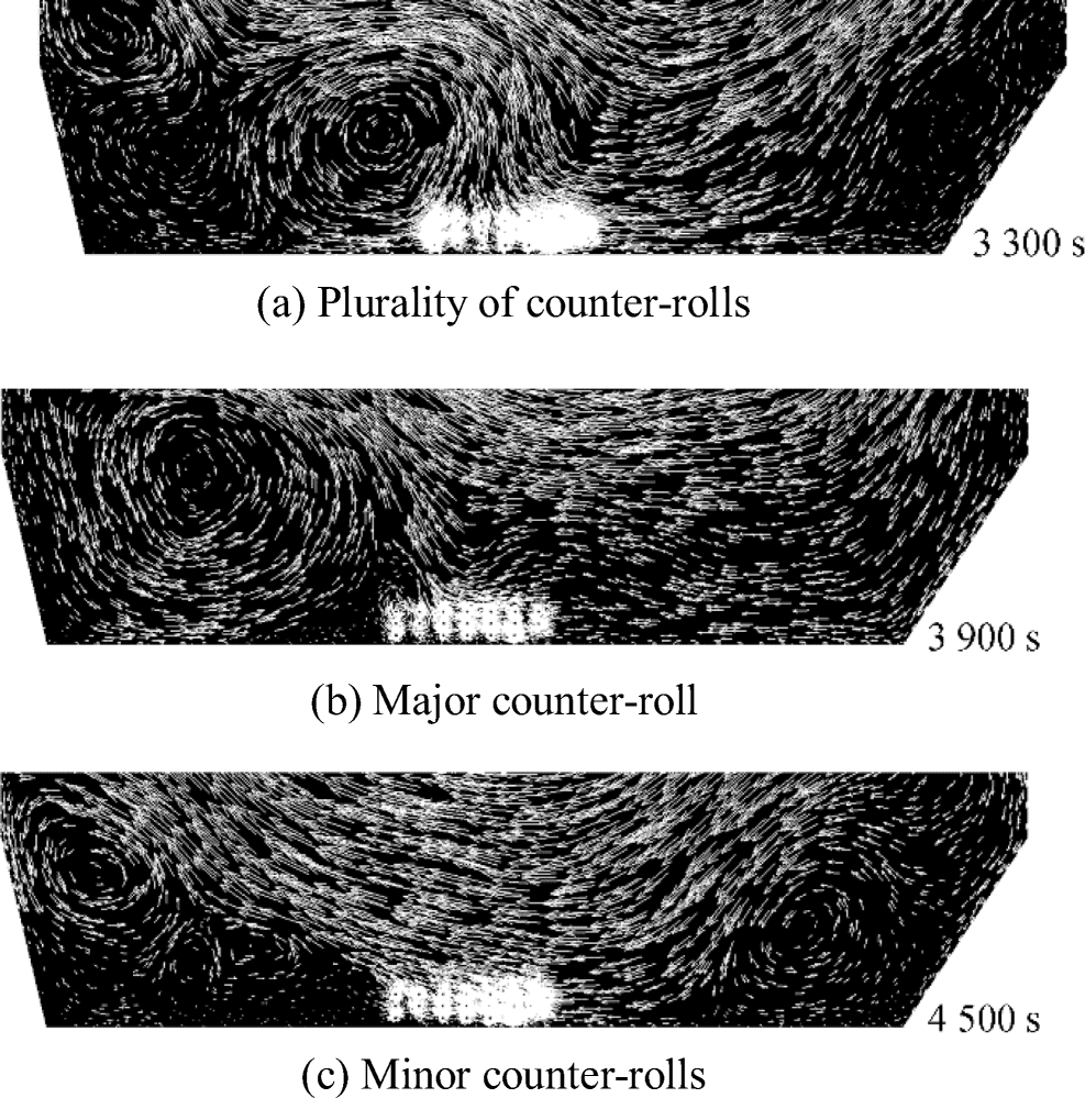 Figure 12 Velocity vectors at the bottom of the tank, three-level bundle
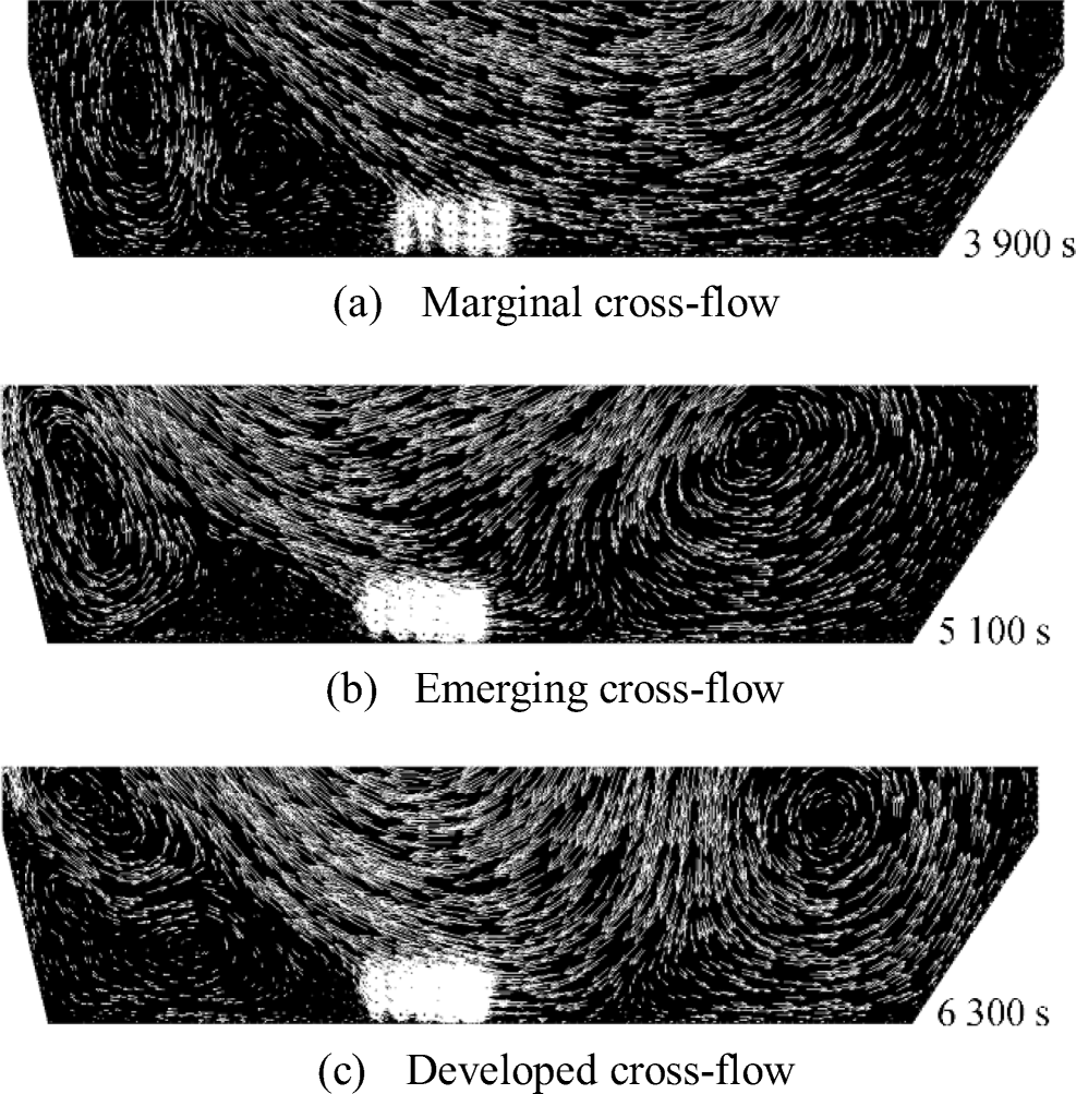 Figure 13 Velocity vectors at the bottom of the tank, four-level bundle
The figures depict the similarities in the structure of the oil flow generated by both the three- and four-level bundles. In addition to the dominant, large-scale circulation, minor counter-rolls are also possible in the tank corners (Figures 12c and 13a). From time to time, only one counter-roll exists (Figure 12b), but multiple counter-rolls emerge otherwise (Figures 12a and 13c).
The thermal performance of the heating coil bundle is determined primarily by the intensity of the oil cross-flow. With marginal oil cross-flow through the bundle (Figure 13a), the coil heat transfer coefficient is low (131.7 W/m2K). However, with full or nearly full cross-flow through the bundle (Figure 13c), the corresponding heat transfer coefficient is high (177.0 W/m2K).
The long large-scale circulation paths along the tank bottom (Figures 12b and 13a) practically act as a self-cleaning mechanism. A similar effect results from the temporary counter-rolls. However, the zones of negligible oil velocity increase the possibility that residue will settle on the tank bottom.
To further investigate this phenomenon, two sets of 29 equidistant probes were established, one set each positioned 25 mm and 50 mm above the bottom of the tank (Figure 14). In the case of the three-level bundle, probes numbered 13 to 17 are positioned just below the bundle, probes numbered 18 to 29 span the bundle's inflow zone (between the bundle and double-side of the tank), and probes numbered 1 to 12 cover the bundle's outflow zone (between the bundle and longitudinal bulkhead). Similarly, in the case of the four-level bundle, the probes numbered 12 to 15 are positioned below the bundle, while the remaining ones follow the above-defined arrangement.
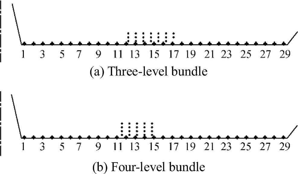 Figure 14 Probes arrangement
The study only takes the horizontal velocity components (Ux) into account; vertical velocity components are assumed to have a marginal effect on the oil mixing in the bottom area of the tank. The results are summarized in Figures 15, 16, 17, and 18.
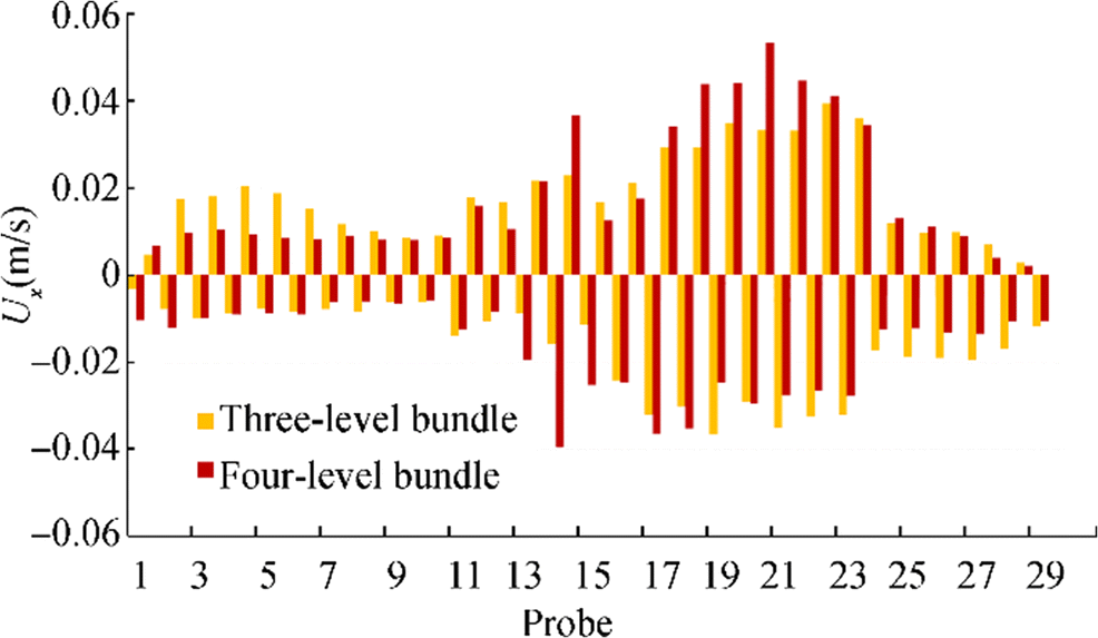 Figure 15 Peaks of the horizontal velocity component at probes 25 mm above the bottom of the tank
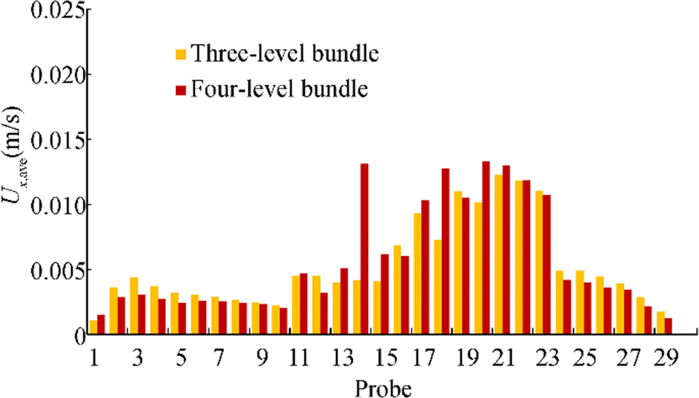 Figure 16 Time-average horizontal velocity components at probes 25 mm above the bottom of the tank
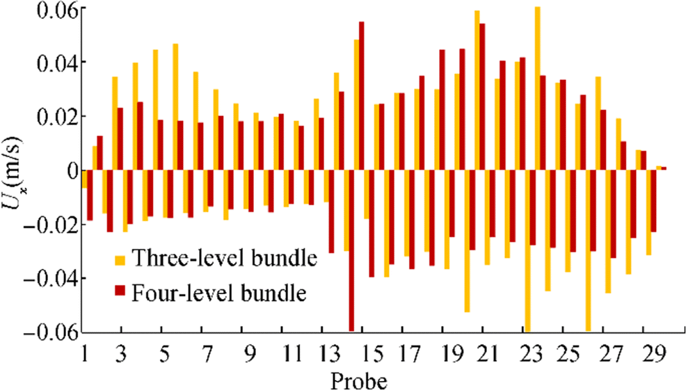 Figure 17 Peaks of the horizontal velocity component at probes 50 mm above the bottom of the tank
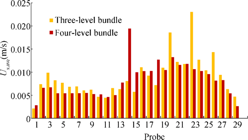 Figure 18 Time-averaged horizontal velocity components at probes 50 mm above the bottom of the tank
Figures 15 and 16 relate to the probes positioned 25 mm above the bottom of the tank, while Figures 17 and 18 concern the probes positioned 50 mm above the bottom of the tank.
Figures 15 and 17 provide the peak horizontal velocity components recorded from t = 3600 s to t = 10 800 s. Regarding the sign convention, positive values refer to flows aligned with the normal to the vessel's longitudinal symmetry plane (i.e., left to right), while negative values concern flows oriented in the opposite direction (i.e., right to left).
Figures 16 and 18 provide, for the same heating period, the time-averaged horizontal velocity components (Ux, ave), distributed along with the probes. At the 25 mm vertical position, small differences are present between the three- and four-level bundles. However, more deviations occur at the 50 mm vertical position. In both cases, probe 14, situated just below the bundles, indicates a significant rise in velocity. This phenomenon may be attributed to the specific suction effect exerted by the adjacent bundle flow.
Table 4 reveals the behavior of the distinct flow zones. The performances of the three- and four-level bundles are comparable. However, the zonal data shows a significant difference between the inflow and outflow zone. The bundle's outflow zone is more prone to the possibility of settled residue than its inflow zone. A significant difference is also noted in the probes positioned just below the bundles. The better performance in the four-level bundle case could be attributed to its smaller breadth, which imposes less pressure loss on the flow.
Table 4 Time-averaged horizontal velocity components close to the bottom of the tankProbes vertical position (mm) 25 50 Three-level bundle (overall) (m/s) 0.0056 0.0092 Inflow zone (m/s) 0.0080 0.0131 Bundle zone (m/s) 0.0068 0.0094 Outflow zone (m/s) 0.0026 0.0052 Four-level bundle (overall) (m/s) 0.0056 0.0083 Inflow zone (m/s) 0.0073 0.0096 Bundle zone (m/s) 0.0093 0.0146 Outflow zone (m/s) 0.0021 0.0044 5 Discussion
The present study reveals that a significant improvement to tank heating effectiveness can be achieved by a proper arrangement of heating coils within the tank. Furthermore, the study also offers evidence contrary to the long-standing belief that an even arrangement of heating coils over the entire bottom of the tank is necessary to obtain well-mixed, uniformly heated cargo. The proposed heating coil arrangements provide several benefits. Firstly, the coils are compact, easy to transport, and erect, enabling significant savings in materials and labor. Secondly, the coils occupy a small portion of the bottom of the tank, leaving greater area free for access, maintenance, and cleaning compared with conventional designs. Finally, significantly less welding work is needed during construction, reducing burnout damage to the tank and double-bottom coatings.
The tank heating problem presented here is a two-dimensional simplification of a three-dimensional reality. The basis for such a simplification lies in the work of Altaç and Uğurlubilek (2016), which revealed that 3D laminar models yield almost identical predictions for mean Nusselt number, and these predictions are compatible with those obtained from 2D simulations, providing a slenderness ratio between 1 and 10. The slenderness ratio is defined as the ratio of tank filling level to tank length. In the present case, this ratio is equal to 1.75, fully complying with the range of validity. A similar justification may be found in Corzo et al. (2011).
The horizontal and vertical tube pitches, proposed in Section 2, follow the arrangement reported in Magazinović (2019). The corresponding horizontal and vertical pitch-to-diameter ratios of 6.61 and 3.31, respectively, are significantly higher than those usually investigated in the literature (Krishne Gouda et al. 1996; Fornarelli et al. 2017). Hence, smaller tube pitches could be more appropriate. For example, given a significantly reduced horizontal pitch of 90 mm (and 180 mm vertical pitch) for a three-level bundle, a time-averaged heat transfer coefficient of 148.7 W/m2K has been achieved. However, due to rising manufacturing and maintenance costs, these small pitches have been abandoned from further study. Also, it is worth noting that the four-level bundle did not much benefit from such an arrangement.
The simulation time of 3 h of heating was selected as a compromise between two mutually conflicting requirements: first, to cover most phenomena developed within the tank and, second, to limit the computational costs incurred to execute the simulation. Consequently, the provided figures do not fully cover all developments. For example, the average heat transfer coefficient (Figs. 6. and 7) tends to rise with heating time due to the falling temperature difference between the coil surface and the bulk oil. Similarly, oil velocity (Figs. 8 and 9) tends to rise, albeit slightly, with heating time. Based on the results obtained during a full-day simulation of a similar three-level bundle (briefly introduced in the previous paragraph), the oil peak and average velocity limits are roughly estimated as 0.269 m/s and 0.102 m/s, respectively. Finally, the tank bottom temperature (Figs. 10 and 11) displays unimodal behavior, characterized by a minimum estimated temperature of 34.7 ℃ (achieved after 4.5 h of heating) and a consequential rise. After a full day of heating, the tank bottom temperature reaches an estimated 41.3 ℃.
Although the effects of heat transfer on the vertical tank walls (e.g., through the double-side or longitudinal bulkhead) may aid or oppose oil circulation, it should be stressed that the influence of the heating coil bundle's position within the tank is much stronger. Furthermore, possible adverse effects of boundary heat outflows could be reasonably easily compensated by updating the bundle's relative position. In doing so, the new position could be determined by a simple but computationally very time-consuming trial-and-error procedure.
The clockwise or counterclockwise sense of heated oil in large-scale circulation is determined by the relative position of heating coil bundles within the tank. From time to time, the sense of rotation can change from clockwise to counterclockwise, as Zhao et al. (2017) showed. Also, heat convection on the tank wall may aid or oppose the direction of circulation (i.e., when the streamlines produced by convection and circulation are counter-oriented). Notably, numerical experiments have shown that convection-aided circulation performs significantly better than convection-opposed circulation.
6 Conclusions
Three- and four-level heating coil bundles, both asymmetrically situated within the transverse tank cross-section, have been proposed and investigated. Numerical study performed by the finite volume method revealed that powerful large-scale circulation of heated fluid enhances the transfer of heat from the heating coils to the surrounding oil.
Furthermore, this circulation improves oil mixing and the uniformity of oil heating. On average, the velocity of heated oil circulation approaches 0.1 m/s, whereas its peaks might reach 0.26 m/s. At the same time, bulk oil temperature varies by less than 1.6 ℃ (excluding zones close to the tank boundary).
In the case of the three-level bundle, the time-averaged heat transfer coefficient rises from 123.5 to 140.3 W/m2K (13.6% enhancement), while it rises from 127.3 to 147.9 W/m2K in the four-level bundle case (16.2% enhancement). Compared with the conventional heating coil designs, the three- and four-level heating coil bundles provide improvements of 16.7% and 23%, respectively, significantly reducing the required heating coil area.
Heat losses at the tank walls expend around 14% of the provided heat inflow, whereas the remaining 86% is available to raise the oil temperature.
The study also quantified the oil flow velocity near the bottom of the tank. The time-averaged horizontal velocity components, estimated at 25 mm and 50 mm above the bottom of the tank, exceed 2 mm/s and 4 mm/s, respectively. The bottom tank area between the heating coil bundle and the longitudinal bulkhead is more prone to possible settling of residue.
The proposed heating coil bundles feature a compact design that reduces material and labor costs in construction, as well as leaving most of the bottom tank plating free of any obstacles and thereby improving accessibility, maintenance, and cleaning.
-
Figure 1 Studied shallow profile heating coil bundles
Figure 2 Tank heating model used in this study
Figure 3 Coil surface temperature distribution
Figure 4 Tank cross-section indicating large-scale circulation generated by a three-level bundle
Figure 5 Tank cross-section indicating large-scale circulation generated by a four-level bundle
Figure 6 Coil heat transfer coefficient, three-level bundle
Figure 7 Coil heat transfer coefficient, four-level bundle
Figure 8 Oil velocity, three-level bundle
Figure 9 Oil velocity, four-level bundle
Figure 10 Oil temperature, three-level bundle
Figure 11 Oil temperature, four-level bundle
Figure 12 Velocity vectors at the bottom of the tank, three-level bundle
Figure 13 Velocity vectors at the bottom of the tank, four-level bundle
Figure 14 Probes arrangement
Figure 15 Peaks of the horizontal velocity component at probes 25 mm above the bottom of the tank
Figure 16 Time-average horizontal velocity components at probes 25 mm above the bottom of the tank
Figure 17 Peaks of the horizontal velocity component at probes 50 mm above the bottom of the tank
Figure 18 Time-averaged horizontal velocity components at probes 50 mm above the bottom of the tank
Table 1 Fuel oil properties at two characteristic temperatures (Magazinović 2018a)
Temperature (℃) 55 157 Model Density (kg/m3) 964 893 linear Dynamic viscosity (Pas) 0.405 0.009 Eq. (1) Thermal conductivity (W/mK) 0.130 0.106 linear Specific heat capacity (J/kgK) 1870 2260 linear Table 2 Oil velocity time-averaged indicators for t > 9000 s
Indicator (m/s) Three-level bundle Four-level bundle Peak velocity 0.258 0.237 Average velocity 0.098 0.093 Table 3 Heat outflow at tank boundary
Boundary (kW) Three-level bundle Four-level bundle Deck 59.2 59.2 Double-side 56.8 56.7 Double-bottom 39.7 38.8 Total 155.7 154.8 Table 4 Time-averaged horizontal velocity components close to the bottom of the tank
Probes vertical position (mm) 25 50 Three-level bundle (overall) (m/s) 0.0056 0.0092 Inflow zone (m/s) 0.0080 0.0131 Bundle zone (m/s) 0.0068 0.0094 Outflow zone (m/s) 0.0026 0.0052 Four-level bundle (overall) (m/s) 0.0056 0.0083 Inflow zone (m/s) 0.0073 0.0096 Bundle zone (m/s) 0.0093 0.0146 Outflow zone (m/s) 0.0021 0.0044 -
Akagi S (1969) Heat transfer in oil tanks of ships. Japan Shipbuild Mar Eng 4(2): 26–35 Akagi S, Kato H (1987) Numerical analysis of mixed convection heat transfer of a high viscosity fluid in a rectangular tank with rolling motion. Int J Heat Mass Transf 30(11): 2423–2432 https://doi.org/10.1016/0017-9310(87)90232-8 Akagi S, Takemura M, Uchida K (1985) Natural convection heat transfer in tank-heating of high viscous oils including a low grade fuel and a coal oil mixture (COM). Bull MESJ 13(1): 4–18 Akagi S, Uchida K, Takemura M (1986) A computer simulation of the natural convection of a high viscosity fluid contained in a two-dimensional tank. Trans JSME (Ser B) 52: 609–616 (in Japanese) https://doi.org/10.1299/kikaib.52.609 Altaç Z, Uğurlubilek N (2016) Assessment of turbulence models in natural convection from two- and three-dimensional rectangular enclosures. Int J Therm Sci 107: 237–246. https://doi.org/10.1016/j.ijthermalsci.2016.04.016 Anon (2014) RMI ASTM D341 rev01. xls, Razaghi Meyer International, Beare Green, United Kingdom, http://www.viscoanalyser.com/page8.html [Accessed on Nov. 11, 2014] Baïri A, Zarco-Pernia E, García de María JM (2014) A review on natural convection in enclosures for engineering applications. The particular case of the parallelogrammic diode cavity. Appl Therm Eng 63(1): 304–322. https://doi.org/10.1016/j.applthermaleng.2013.10.065 Bhutta MMA, Hayat N, Bashir MH, Khan AR, Ahmad KN, Khan S (2012) CFD applications in various heat exchangers design: a review. Appl Therm Eng 32: 1–12 https://doi.org/10.1016/j.applthermaleng.2011.09.001 Bridan EV (1979) System for heating-up viscous cargo in ship tanks. Soviet Union Patent Application SU703422 A1 Celik IB, Ghia U, Roache PJ, Freitas CJ, Coleman H, Raad PE (2008) Procedure for estimation and reporting of uncertainty due to discretization in CFD applications. J Fluids Eng 130(7): 078001 https://doi.org/10.1115/1.2960953 Corzo SF, Damián SM, Ramajo D, Nigro NM (2011) Numerical simulation of natural convection phenomena. Mecanica Computacional 30: 277–296 Couchman AAJ, Dowie WF, McClimont W (1966) Heating of high-viscosity oil cargoes. Trans Inst Marine Eng 78: 53–71 Fornarelli F, Lippolis A, Oresta P (2017) Buoyancy effect on the flow pattern and the thermal performance of an array of circular cylinders. J Heat Transf 139: 022501 https://doi.org/10.1115/1.4034794 Greenshields CJ (2015) OpenFOAM: the open source CFD toolbox, OpenFOAM Foundation, Bracknell, Great Britain, User Guide, Version 3.0.1 Guo S (2017) Boats and ships cargo oil cabin heating coil's arrangement structure. China Utility Model CN206579828 U Guo Z, Lu J, Shang G, Tong K, Wu W, Xu B (2017) Steam microwave composite heating device. China Utility Model CN206734600 U Jandrijević B, Mrakovčić T, Račić R (2007) Analysis of heat transfer in ships' cargo tanks. Strojarstvo 49: 225–231 Kang J, Kang K (2016) Drum heater. Korea Patent KR101623839 B1 Khanafer K, Vafai K, Lightstone M (2003) Buoyancy-driven heat transfer enhancement in a two-dimensional enclosure utilizing nanofluids. Int J Heat Mass Transf 46(19): 3639–3653. https://doi.org/10.1016/S0017-9310(03)00156-X Krishnamurti R, Howard LN (1981) Large-scale flow generation in turbulent convection. Proc Natl Acad Sci USA 78(4): 1981–1985 https://doi.org/10.1073/pnas.78.4.1981 Krishne Gouda YT, Aswatha Narayana PA, Seetharamu KN (1996) Numerical investigation of mixed convection heat transfer past an in-line bundle of cylinders. Heat Mass Transf 31: 347–352 https://doi.org/10.1007/BF02184049 Kurihara T, Amagata H, Maekawa C (1972) Experimental studies on heat transfer coefficients and effective length of tank heating coils in vessels. Sel Papers J Soc Naval Architects Japan 10: 129–144 Kuznetsova SA (2015) Numerical modeling of heat transfer in the fuel oil storage tank at thermal power plant. EPJ Web of Conferences 82: 01027. https://doi.org/10.1051/epjconf/20158201027 Magazinović G (1987) Computer aided design and analysis of tank heating. Brodogradnja 35(4–5): 193–202 (in Croatian) Magazinović G (2018a) Cargo tank heating using vertically arranged heating coils. SORTA 2018, Split, Croatia, 349-356 Magazinović G (2018b) Multi-level heating coil bundle. International Patent Application WO2018234380 A1 Magazinović G (2019) Vertical arrangement of coils for efficient cargo tank heating. Int J Naval Archit Ocean Eng 11(2): 662–670. https://doi.org/10.1016/j.ijnaoe.2019.02.004 Matthews TPW (1962) Improvements relating to heating apparatus for liquid cargo tanks of ships. Great Britain Patent GB897346 Mohn F (1969) Improved system and units for heating a liquid cargo in a ship's tank. Norway Patent NO121316 B Moukalled F, Mangani L, Darwish M (2016) The finite volume method in computational fluid dynamics: an advanced introduction with OpenFOAM and Matlab, vol 130. Springer, Cham. https://doi.org/10.1115/1.2960953 Nakamoto M, Takeshita NN (1981) Oil heating unit. Japan Utility Model Application JP56044640 Y Okano S (2011). Arrangement structure for oil tank inner heat pipe in vessel. Japan Patent JP4633660 B2 Pivac I, Magazinović G (2015) Numerical analysis of tank heating coil heat transfer process. In: Guedes Soares C et al (eds) Towards green marine technology and transport. Taylor & Francis Group, London, pp 603–608 Saunders RJ (1968) Heat losses from oil-tanker cargoes. Trans Inst Marine Eng 90: 405–414 Shin D, Jee J, Kang NC (2015) Non-welded oil heating device drum type. Korea Patent KR101494581 B1 Sitarski D, Lee RJ, Saylor JR, McHugh JP (2013) Large-scale circulation in a rectangular enclosure with periodic boundary temperature. J Fluids Eng 135(7): 071201. https://doi.org/10.1115/1.4024011 Sreenivasan KR, Bershadskii A, Niemela JJ (2002) Mean wind and its reversal in thermal convection. Phys Rev E 65(5): 056306. https://doi.org/10.1103/PhysRevE.65.056306 Suhara J (1970) Studies of heat transfer on tank heating of tankers. Japan Shipbuild Mar Eng 5(1): 516 Sun W, Cheng Q, Zheng A, Gan Y, Gao W, Liu Y (2018) Heat flow coupling characteristics analysis and heating effect evaluation study of crude oil in the storage tank different structure coil heating processes. Int J Heat Mass Transf 127: 89–101. https://doi.org/10.1016/j.ijheatmasstransfer.2018.08.035 Van der Heeden DJ, Mulder LL (1965) Heat-transfer in cargotanks of a 50, 000 dwt tanker. Int Shipbuild Prog 12(132): 309–328 https://doi.org/10.3233/ISP-1965-1213201 Warrington RO, Crupper G (1981) Natural convection heat transfer between cylindrical tube bundles and a cubical enclosure. J Heat Transf 103(1): 103–107 https://doi.org/10.1115/1.3244401 Xi HD, Zhou Q, Xia KQ (2006) Azimuthal motion of the mean wind in turbulent thermal convection. Phys Rev E 73(5): 056312. https://doi.org/10.1103/PhysRevE.73.056312 Yang L, Zhao J, Dong H, Liu J, Zhao W (2018) Research on temperature profile in a large scaled floating roof oil tank. Case Stud Thermal Eng 12:805–816. https://doi.org/10.1016/j.csite.2018.10.009 Zhao J, Dong H, Wang X, Fu X (2017) Research on heat transfer characteristic of crude oil during the tubular heating process in the floating roof tank. Case Stud Thermal Eng 10:142–153. https://doi.org/10.1016/j.csite.2017.05.006 Zolling R (1914) Tank-ship. U.S. Patent US1103239