Effects of Wind-Wave Misalignment on a Wind Turbine Blade Mating Process: Impact Velocities, Blade Root Damages and Structural SafetyAssessment
https://doi.org/10.1007/s11804-020-00141-7
-
Abstract
Most wind turbine blades are assembled piece-by-piece onto the hub of a monopile-type offshore wind turbine using jack-up crane vessels. Despite the stable foundation of the lifting cranes, the mating process exhibits substantial relative responses amidst blade root and hub. These relative motions are combined effects of wave-induced monopile motions and wind-induced blade root motions, which can cause impact loads at the blade root's guide pin in the course of alignment procedure. Environmental parameters including the wind-wave misalignments play an important role for the safety of the installation tasks and govern the impact scenarios. The present study investigates the effects of wind-wave misalignments on the blade root mating process on a monopile-type offshore wind turbine. The dynamic responses including the impact velocities between root and hub in selected wind-wave misalignment conditions are investigated using multibody simulations. Furthermore, based on a finite element study, different impact-induced failure modes at the blade root for sideways and head-on impact scenarios, developed due to wind-wave misalignment conditions, are investigated. Finally, based on extreme value analyses of critical responses, safe domain for the mating task under different wind-wave misalignments is compared. The results show that although misaligned wind-wave conditions develop substantial relative motions between root and hub, aligned wind-wave conditions induce largest impact velocities and develop critical failure modes at a relatively low threshold velocity of impact.Article Highlights• The effects of wind-wave misalignments on the blade root mating process on a monopile-type offshore wind turbine is investigated.• The collinear wind-wave conditions cause sideways impact, whereas head-on impact is developed dominantly due to misaligned wind-wave conditions.• Collinear wind-wave condition is found to have the lowest percentage of safe domain for mating task.• The sideways' impact of the guide pin with hub is more critical than the head-on impact, and the failure criteria in the root laminate are met at a relatively low velocity of impact.Article HighlightsOpen Access This article is licensed under a Creative Commons Attribution 4.0 International License, which permits use, sharing, adaptation, distribution and reproduction in any medium or format, as long as you give appropriate credit to the original author(s) and the source, provide a link to the Creative Commons licence, and indicate if changes were made. The images or other third party material in this article are included in the article's Creative Commons licence, unless indicated otherwise in a credit line to the material. If material is not included in the article's Creative Commons licence and your intended use is not permitted by statutory regulation or exceeds the permitted use, you will need to obtain permission directly from the copyright holder. To view a copy of this licence, visit http://creativecommons.org/licenses/by/4.0/. -
1 Introduction
In order to resolve the issues related to global warming and climate change, there is a continuous demand for renewable sources of energy. In Europe, wind energy ranks second in terms of power generation (Wind Europe 2017a), and immense political and scientific interest is placed on the growth of offshore wind turbines (OWTs). Monopile-type OWTs are the most popular choice of turbines in shallow waters, and currently account for more than 87% of the market share (Wind Europe 2017b). One of the main challenges in the industry includes high installation and assembly cost (Molla 2015) associated with the project cycle of OWTs, and therefore, recent trends involve deploying large size OWTs. This facilitates having less number of turbine units at an offshore farm, thus reducing the overall installation cost. However, several safety issues are inevitably present during the installation of bigger and heavier turbine components. For example, components like blades and nacelle are structurally delicate and demand absolute precision during transportation and installation.
Generally, blades of a monopile-type offshore wind turbine are installed using jack-up crane vessels (Verma et al. 2017; Verma et al. 2019a; Ren et al. 2018a) (Figure 1a). Individual pieces are hoisted to the hub, and blade root consisting of several bolted connections, together with the guide pin, is mated with the hub's flange holes (Verma et al. 2019b). The guide pins are long-sized bolts (Figure 1b–c) and are inserted in the blade root to visually aid the offshore crew (present in the nacelle) while performing the mating task.
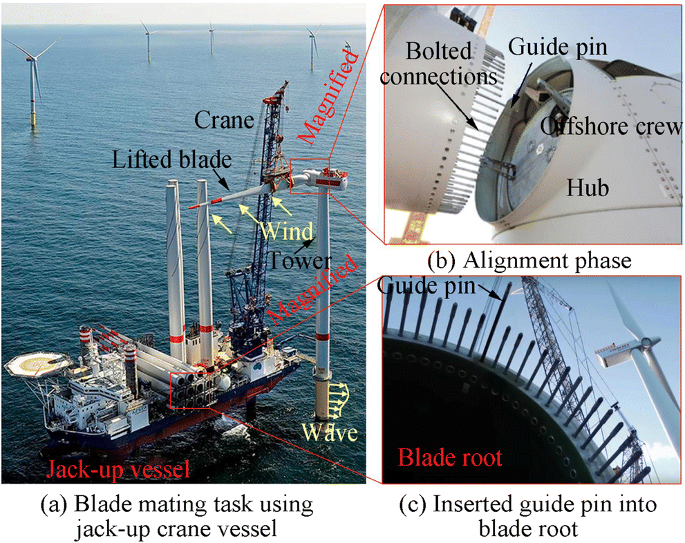 Figure 1 Blade root mating process (https://orsted.com/en) (https://vessels.offshorewind.biz/vessels/sea challenger) (https://www.siemens.com)
Despite the stable foundation of the jack-up crane vessels, the mating process suffers substantial relative responses amidst blade root and hub (Jiang et al. 2018; Ren et al. 2018b; Ren et al. 2019). The blade root motions are a result of wind-induced loads on the lifted blade, whereas the hub responses are caused by wave actions on the preassembled monopile structures. Note that monopiles are large diameter structures fixed to the seabed and have low damping characteristics (Jiang 2018). For example, the monopiles have deficient structural, hydrodynamic and soil-damping attributes. The damping is even more critical during the installation phase as the aerodynamic damping from the rotating blades is missing. Thus, large dynamic amplification of tower top responses develops and contributes to excessive relative motions while performing the mating task. This can induce impact loads at the guide pin during the alignment process, causing critical damages at the blade root and thus, failure of installation task. Verma et al. (2019a) investigated impact assessment of wind turbine blade root during offshore mating process where relative responses under aligned wind-wave conditions were investigated. Furthermore, damage assessment at the blade root was studied, and bending of guide pin and delamination of root laminate were found as failure modes. Nevertheless, mating operations under misaligned wind-wave conditions were not considered, and damages for such scenarios were not assessed. In practice, for an offshore site, wind-wave misalignments are present for all ranges of wind speeds, and therefore, it is important to investigate such effects for the success of the wind turbine blade mating process. Wind-wave misalignment is the measure of temporal difference between the wind direction and mean wave directions (Van Vledder 2013), where highest degree of misalignments is found at low wind speeds, and minor misalignments are found at high wind speeds (Li et al. 2015; Van Vledder 2013; Bachynski et al. 2014).
Figure 2a–d present the relative frequency of wind direction, mean wave directions and misalignment between wind and waves for the North Sea centre. It can be clearly seen that though the wind and waves are spread out in all directions, the misalignment between wind-wave is mostly concentrated between 0° and 90°. Majority of the misalignment occurs till 30°, with frequency being less than 5% for wind-wave misalignment greater than 60° (Bachynski et al. 2014). Currently, there are limited published literature sources (Jiang et al. 2018; Verma et al. 2019c; Verma et al. 2019d; Verma et al. 2020a; Verma et al. 2020b) dealing with the effects of wind-wave misalignment on the installation phases of OWTs, although several studies in the past emphasised operational and parked conditions of OWTs for design purposes. Barj et al. (2014), Bachynski et al. (2014) and Zhou et al. (2017) investigated the effect of misalignment on the operational loads for floating OWTs, whereas Fischer et al. (2011) investigated the effect of misalignment on monopile-type OWTs. The response parameters of interest for such assessments were tower top motions, bending moments and fatigue damages. On the other hand, in this study, the mating process of blade is studied, and therefore, the response parameters of interest are related to the critical event that can cause failure of the installation task. These include (1) impact velocity between root and hub during mating, (2) impact-induced damages at the blade root and (3) structural safety assessment of the mating task for a given wind-wave misalignment condition.
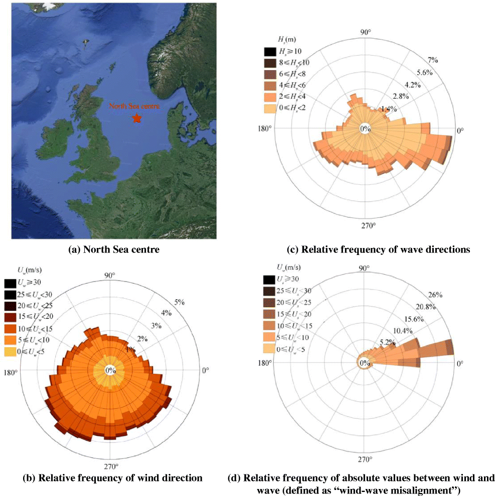 Figure 2 Different wind and wave directions (wind and wave direction corresponds to a compass—0° represents East, 90° North, 180° West and 270° represents South)
The present paper investigates the effect of wind-wave misalignment for the blade root mating process where dynamic responses including the impact velocities in selected wind-wave misalignment conditions are investigated using multibody simulations in HAWC2 (Larsen and Hansen 2007). Furthermore, based on a finite element study in Abaqus/explicit (Hibbitt et al. 2016), impact-induced failure modes at the blade root are discussed. Finally, safe domain for the mating task is compared for different wind-wave misalignment conditions. The remainder of the paper proceeds as follows. Section 2 presents the analysis procedure and identifies relevant response parameter for investigating effects of wind-wave misalignment. Section 3 presents the material and modelling methods. Section 4 presents and discusses the results. Finally, Section 5 concludes the paper.
2 Response Parameters and Analysis Procedure
There are three response parameters identified in this paper to investigate the effects of wind-wave misalignment on the wind turbine blade mating process and are described below:
2.1 Impact Velocity between Root and Hub
This is the most critical response parameter of interest for the blade mating task and determines the impact scenarios for the blade root's guide pin. These responses are governed partially by wind-induced blade root responses and partially by wave-induced hub motions. Impact velocities in two different directions and corresponding impact scenarios are defined. (1) Impact velocity in the side-side direction ($ {V}_x^{\mathrm{imp}} $) causes head-on impact of the guide pin (Figure 3). Here, contact region of the guide pin lies along its axial direction. $ {V}_x^{\mathrm{imp}} $ is defined as relative velocity among root and hub in global x-direction: $ {V}_x^{\mathrm{hub}}-{V}_x^{\mathrm{root}} $. While, (2) impact velocity in the fore-aft direction ($ {V}_y^{\mathrm{imp}} $) causes sideways' impact of the guide pin, and contact region lies along its transverse direction. $ {V}_y^{\mathrm{imp}} $ is defined as relative velocity between root and hub in the global y-direction: $ {V}_y^{\mathrm{hub}}-{V}_y^{\mathrm{root}} $. These responses vary with wind-wave misalignment and are obtained by global response analysis of the installation system.
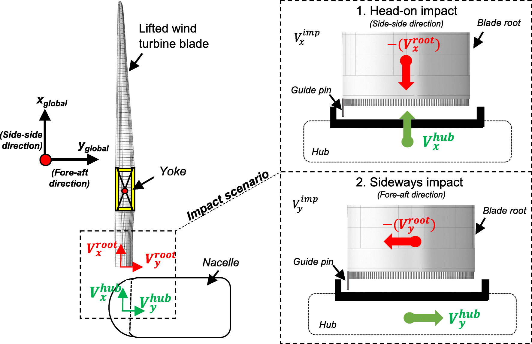 Figure 3 Illustration of impact scenarios during the blade mating process
2.2 Damage Assessment for a Critical Location at the Blade Root
A wind turbine blade usually includes several T-bolt connections attached at its root (Ketele 2013; Martınez et al. 2011). A T-bolt connection comprises of an assembly of steel bolt and barrel nut, which are drilled into the blade root laminate (Brøndsted and Nijssen 2013). In Verma et al. (2019a), it was found that impact loads at blade root causes through-the-thickness tensile normal stresses (σ33 > 0). This leads to delamination of the plies at location z of the blade root (Figure 4), which is the most critical location of failure. In this paper, damage assessment at location z is performed for both contact scenarios—sideways' impact and head-on impact, and allowable impact velocities in the fore-aft ($ {V}_y^{\mathrm{allow}} $) and side-side direction ($ {V}_x^{\mathrm{allow}} $) are obtained. A normalised failure index ($ {I}_f^z\left({S}_{33}\right) $) is defined which represents stress exposure factor at location z and is given by:
$$ {I}_f^z\left({S}_{33}\right)=\left(\frac{\sigma_{33}^z}{Z^T}\right) $$ (1) 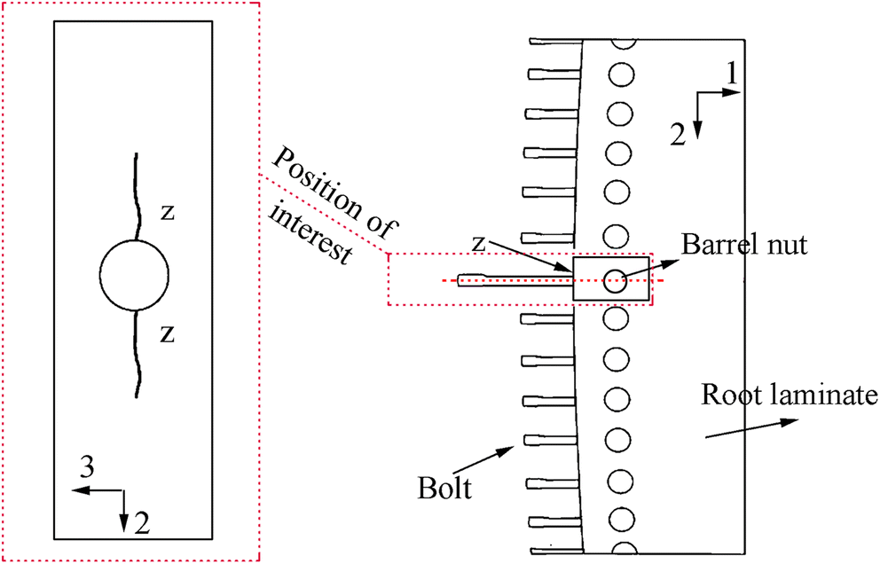 Figure 4 Position of interest at the blade root for assessment
where $ {\sigma}_{33}^z $ is the through-the-thickness tensile normal stresses at location z, and ZT denotes through-the-thickness tensile strength. Note that $ {I}_f^z\left({S}_{33}\right)\ge 1 $ represents failure in the root laminate at position z.
2.3 Structural Safety Assessment of the Mating Task for a Sea State with Given Wind-Wave Misalignment
This response parameter measures whether the sea state with a given wind-wave misalignment condition is safe or not for the mating task. Here, extreme value analysis is performed for velocity of impact in both, fore-aft ($ {V}_y^{\mathrm{imp}} $) and side-side direction ($ {V}_x^{\mathrm{imp}} $), and corresponding extreme value distributions is obtained for load cases with different wind-wave misalignment conditions.
Furthermore, for a target safety level, characteristic extreme responses ($ {V}_x^{\mathrm{char}},{V}_y^{\mathrm{char}} $) are obtained (Verma et al. 2019c) and are compared with allowable impact velocities ($ {V}_x^{\mathrm{allow}},{V}_y^{\mathrm{allow}} $). Only those sea states are considered safe (xi ∈ S) for the mating task in which the characteristic extreme responses are less than allowable impact velocities in both fore-aft and side-side direction. A criterion was proposed in the previous work (Verma et al. 2019c) for safety assessment of mating task and is given by:
$$ {\displaystyle \begin{array}{ll}& \forall {x}_i\in {H}_s,{T}_p,{U}_w,{\beta}_{\mathrm{wave}}\\ {}& \mathrm{if}\ {V}_x^{\mathrm{char}}\le {V}_x^{\mathrm{allow}}\ \mathrm{and}\ {V}_y^{\mathrm{char}}\le {V}_y^{\mathrm{allow}}\\ {}& \mathrm{then}\ {x}_i\in S\ \left(\mathrm{sea}-\mathrm{state}\ \mathrm{safe}\ \mathrm{for}\ \mathrm{mating}\right)\\ {}& \mathrm{else}\ {x}_i\notin S\ \left(\mathrm{unsafe}\right)\ \end{array}} $$ (2) where xi is the load case considered for analysis, Hs is the significant wave height, Tp is the wave spectral peak period, Uw is the mean wind speed at hub height, βwave is the degree of misalignment for wind-wave, $ {V}_x^{\mathrm{char}} $ and $ {V}_y^{\mathrm{char}} $ are characteristic extreme responses corresponding to a target safety level in side-side and fore-aft direction of the installation system respectively, and $ {V}_x^{\mathrm{allow}} $, $ {V}_y^{\mathrm{allow}} $ are allowable impact velocities in side-side and fore-aft direction, respectively. It is to be also noted that the target exceedance level for calculating the characteristic extreme responses from extreme value distributions is considered as 10−2 per operation in this study. This value corresponds to the consequence level where there are no damages developed in the composite root laminate, and another mating trial is possible after replacing damaged guide pins (Verma et al. 2019c). The target exceedance level of 10−2 for the response parameters we considered here corresponds to a target safely level with a failure probability of 10−2, representing 1 failure per 100 operations (and corresponding consequence), and is based on such incidents reported in the industry.
Analysis Procedure
Figure 5 presents the analysis procedure followed in this study for investigating the effect of wind-wave misalignment on the wind turbine blade mating process. There are three distinct yet interrelated steps, where each step emphasises on the quantification of the above-discussed response parameters.
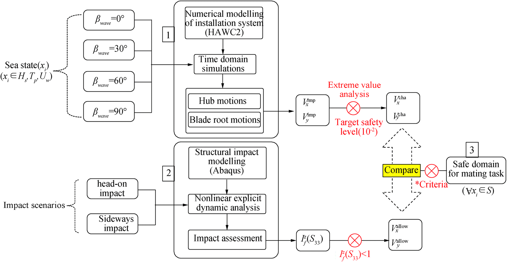 Figure 5 Analysis procedure considered in this study
The first step includes numerical modelling of the mating process in HAWC2 code (Larsen and Hansen 2007), where four different wind-wave misalignment conditions (βwave = 0°, 30°, 60°, 90°) are considered for time domain analysis. Note that the choice of wind-wave misalignment for the analysis is site-specific and represents conditions for the North Sea centre in this study. The hub motions and blade root motions are calculated and finally $ {V}_y^{\mathrm{imp}} $ and $ {V}_x^{\mathrm{imp}} $ are obtained for given wind-wave misalignment conditions.
The second step is impact assessment of the blade root with hub using finite element analysis. The response parameter $ {I}_f^z\left({S}_{33}\right) $ is evaluated for both impact scenarios, and allowable impact velocities ($ {V}_x^{\mathrm{allow}} $, $ {V}_y^{\mathrm{allow}} $) are obtained for impact scenarios in fore-aft and side-side direction.
The final step is the structural safety assessment of the mating task for given wind-wave misalignment conditions. The extreme value analysis is performed for the response parameter $ {V}_x^{\mathrm{imp}} $ and $ {V}_y^{\mathrm{imp}} $, and for a target safety level of 10−2 per operation, characteristic extreme responses ($ {V}_x^{\mathrm{char}},{V}_y^{\mathrm{char}} $) are obtained for different misalignments. These characteristic responses are then compared with allowable level of impact velocities ($ {V}_x^{\mathrm{allow}} $, $ {V}_y^{\mathrm{allow}} $), and only those sea states (xi) are considered safe for the mating task for which the criteria defined by Eq. (2) are satisfied. Finally, an overall safe domain for the mating task which consists of all safe sea states (∀xi ∈ S) is compared for different wind-wave misalignment conditions.
3 Material and Modelling Methods
The mating process of DTU 10 MW wind turbine blade (Bak et al. 2013) is considered in this article, and thus, all the parameters used for modelling are derived from DTU 10 MW report (Bak et al. 2013). Here, the modelling details of the installation system using multibody dynamics are described first. Then, the finite element modelling information for impact analysis between blade root and hub for different scenarios are addressed.
3.1 Numerical Modelling of Installation System
The installation system is modelled in HAWC2 numerical code (Larsen and Hansen 2007). The code can simulate dynamics of the wind turbines in the time domain considering various effects such as wind and waves. The installation system consists of two independent sub-systems—(1) preassembled monopile sub-system, and (2) single-blade lift sub-system (Figure 6). Different modelling aspects are considered in HAWC2 and are discussed below.
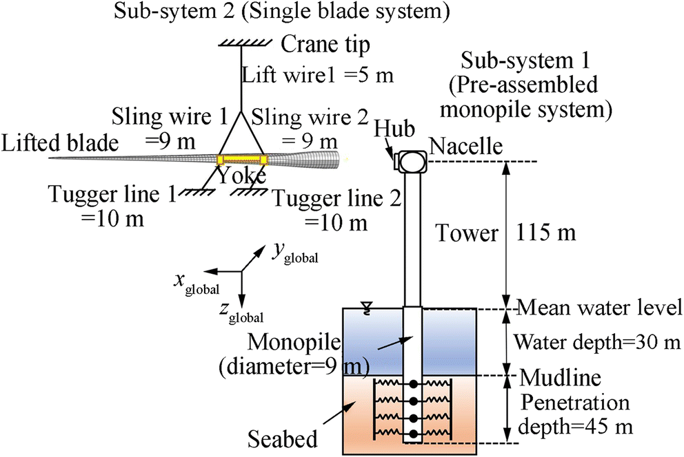 Figure 6 Description of numerical modelling of installation system
Structural Model
In the HAWC2 code, the structural formulation of the turbine components depends upon multibody dynamics. The first structural system, i.e. (1) preassembled monopile system consists of a monopile, along with a turbine tower, a nacelle and a hub. The components of this sub-system are grouped into several flexible bodies, and are modelled with Timoshenko beam elements linked through a coupling joint. Large rotations and large displacements are permissible at these joints; however, only small deflections are allowed within each body.
The (2) single-blade lift-sub-system on the other hand consists of the wind turbine blade, yoke, tugger lines, lift and sling wires connected to a fixed crane tip. The wind turbine blade is discretised with Timoshenko beam elements, and is defined as one single body. The yoke is added as a concentrated rigid body defined at the mass centre of the blade. The tugger lines are 10 m long and consist of cable bodies joined by spherical joints (Verma et al. 2019a). It is to be noted that the effect of jack-up crane vessel is ignored in this study as the vessel is generally stable due to load bearing legs, and thus has a minor contribution to crane tip responses. The structural characteristics of components used in the modelling of installation system are also mentioned in Table 1.
Table 1 Modelling parameters of installation system used in HAWC2Parameter Values Diameter of monopile (m) 9 Pile penetrating depth (m) 45 Water depth (m) 30 Eigen period - first fore-aft mode (s) 4.2 Damping ratio - first fore-aft mode (%) 1 Blade mass (t) 41.7 Blade length (m) 86.4 Blade root diameter (m) 5.4 Yoke weight (t) 50 Pile-Soil Interaction Model
The monopile support structure along with the characteristics of soil layers used in this study is based on the work of Velarde (2016), where the foundation for DTU 10 MW reference turbine was designed. In Velarde (2016), only the non-linear p − y curve corresponding to soil lateral stiffness was reported and this makes the basis for pile-soil interaction model in our study. The pile diameter is around 9 m and has a penetration depth of 45 m. The distributed springs model is utilised, which considers the pile as a flexible component having lateral springs spread around the soil layer.
Wave-Induced Hydrodynamic Model
Morison equation (Morison et al. 1950) is used to calculate hydrodynamic wave-induced loads exerted on the monopile. The equation consists of inertial as well as drag-associated terms and is given by:
$$\begin{gathered}{f}_s=\rho {C}_m\ \frac{\pi {D}^2}{4}{\ddot{x}}_w-\rho \left({C}_m-1\right)\frac{\pi {D}^2}{4}{\ddot{\eta}}_1\\ +\frac{1}{2}\rho\ {C}_dD\left({\dot{x}}_w-{\dot{\eta}}_1\right)\mid {\dot{x}}_w-{\dot{\eta}}_1\mid\end{gathered}$$ (3) where ρ is defined as the density of sea water, D is the monopile diameter, and Cm and Cd in the above equation are the inertial and drag coefficient and is assumed as 2.0 and 1.0, respectively (Jiang 2018). Furthermore, $ {\dot{x}}_w $ in the above equation describes the velocity, whereas $ {\ddot{x}}_w $ describes the acceleration of water particles at the strip centre.
Wind and Aerodynamic Model
Cross-flow principles are used, which assume the wind flow as 2D, and neglect the wind flow in the span-wise direction of the blade. As the blade is non-rotating, steady lift and drag coefficients are utilised (Bak et al. 2013; Verma et al. 2019b) to calculate aerodynamic loads exerted on blade sections. The Mann's turbulence (Mann 1994) module available in HAWC2 code is utilised to generate inflow turbulent field in this study. This module is defined by three parameters—turbulence length scale factor, eddy lifetime and spectral multiplier. The details of these parameters can be found in Jiang et al. (2018).
3.2 Environmental Load Cases for Time Domain Analysis
In this study, North Sea centre is considered for studying the effect of wind-wave misalignment during offshore blade mating task. The offshore site has a water depth of 29 m, which nears the water depth of 30 m considered for the monopile foundation in this study. Figure 7a and b present the histogram of Hs and Tp, respectively, from 10 years of hindcast data (2001–2010). It can be clearly seen that bulk of Hs for the site is less than 6m, whereas Tp lies in the range of 2 − 16s.
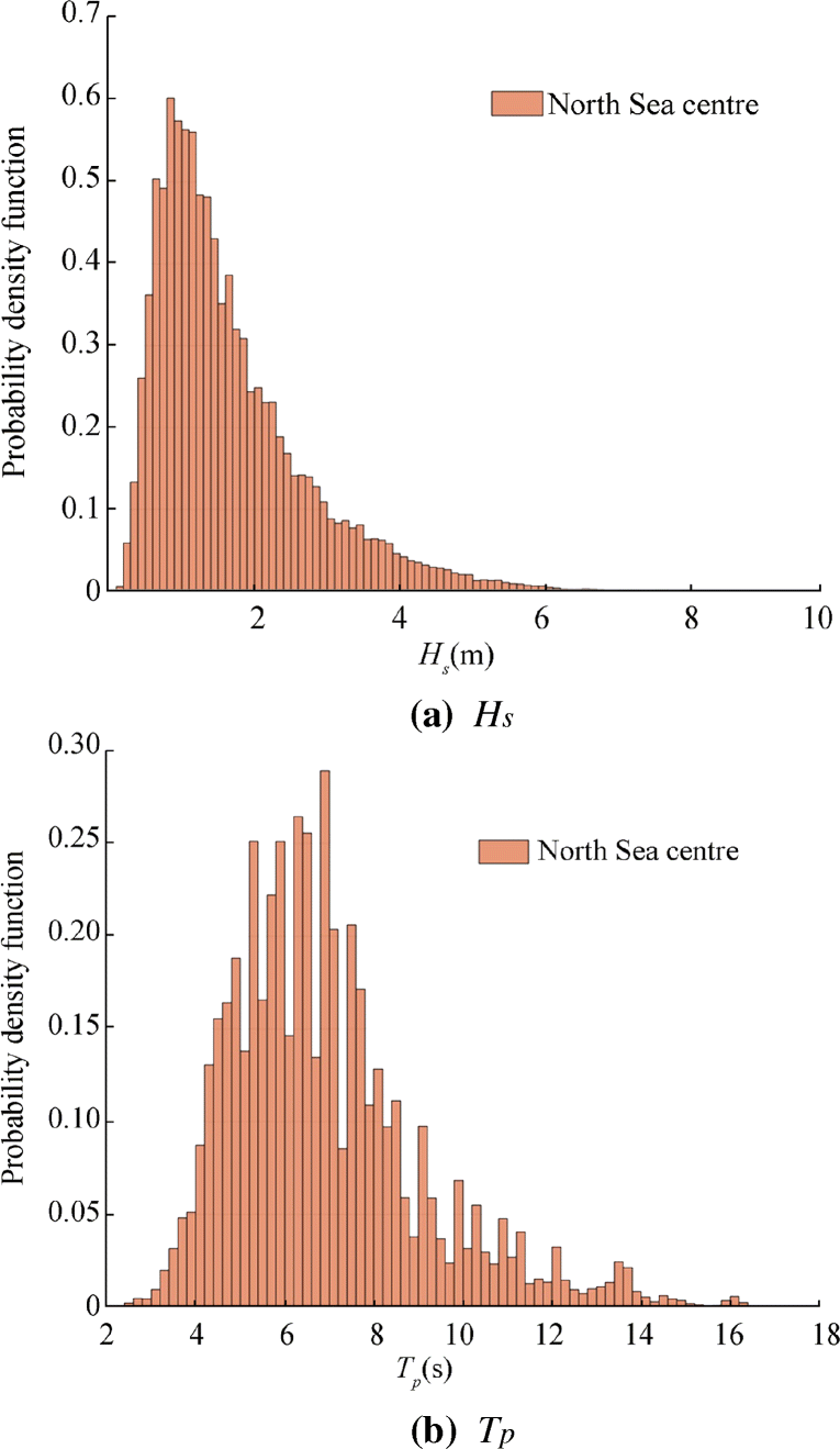 Figure 7 Histogram data at North Sea centre
Given that the mating task is expected to give very high responses for Hs > 3m, the present paper only considers time domain analysis for Hs in the range 1m ≤ Hs ≤ 3m where Hs varies with a step of 0.5m. Again, the analysis considers Tp in the range 4s ≤ Tp ≤ 12s, where Tp varies with a step of 2s. Also, since the site has wind-wave misalignments varying between 0° and 90° (as discussed in Section 1), four cases of wind-wave misalignments (βwave = 0°, 30°, 60° and 90°) are considered for each load case. For simplicity, only one case of mean wind speed (Uw = 10m/s) is considered in this paper and corresponds to turbulence intensity of 0.12 selected from IEC standard (IEC 2005). Figure 8 presents the bird view of the installation process, where different wind-wave misalignments taken in the paper are illustrated. The details of environmental load cases are mentioned in Table 2.
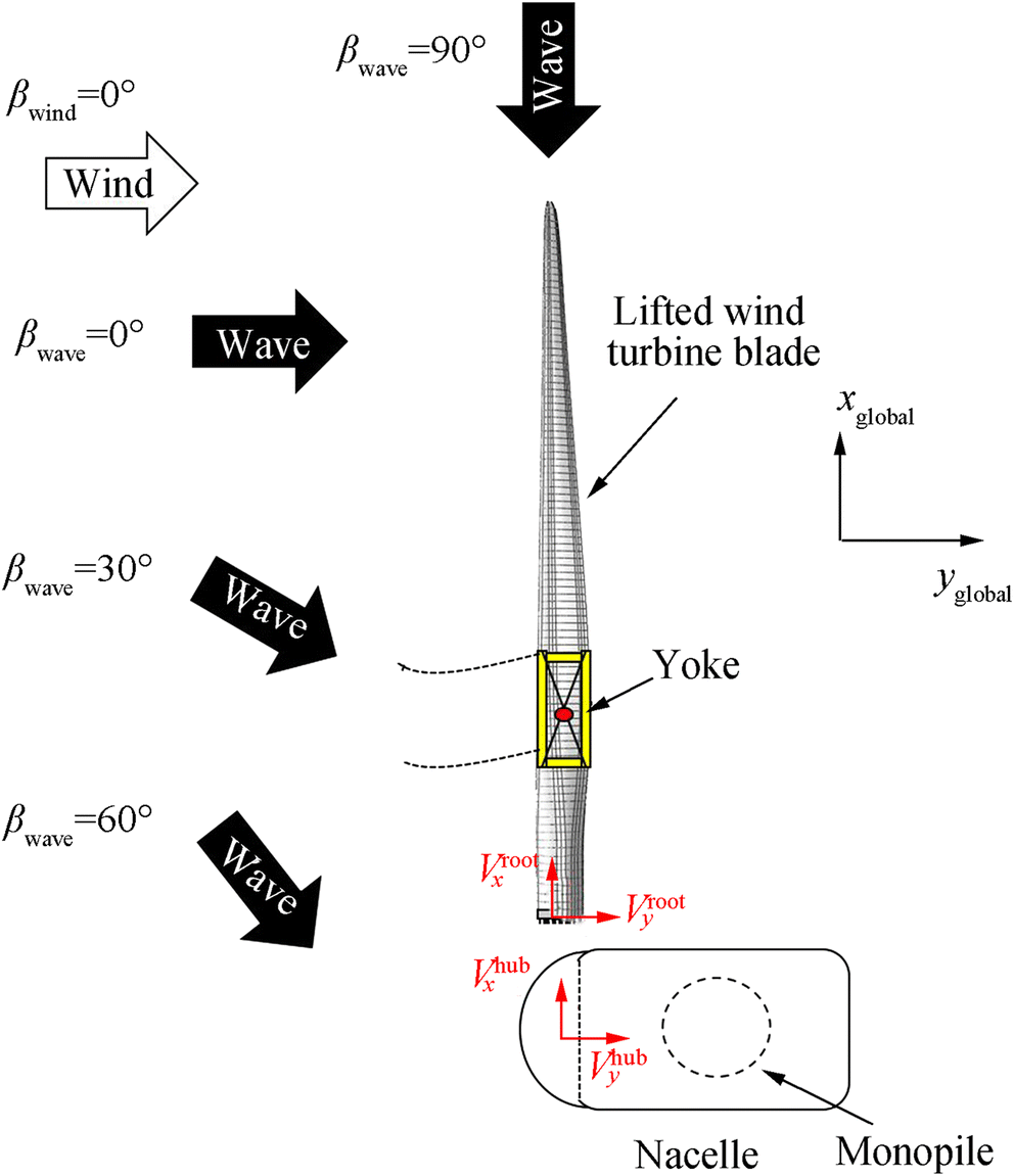 Figure 8 Bird view of mating process with considered wind-wave misalignmentTable 2 Description of environmental load cases
EC βwave (°) Hs (m) Tp (s) Uw (m/s) TI 1 0 1, 1.5, ....3.0 4, 6, ...12 10 0.12 2 30 1, 1.5, ....3.0 4, 6, ...12 10 0.12 3 60 1, 1.5, ....3.0 4, 6, ...12 10 0.12 4 90 1, 1.5, ....3.0 4, 6, ...12 10 0.12 3.3 Time Domain Analyses
Time domain analyses are performed at a time step of 0.01s with each environmental load case analysed for 20 seeds for stochastic variability. Therefore, a total sum of 2000 environmental cases are considered for the time domain analysis. Each case has a total time duration of 1000 s, where first 400 s are removed during post-processing to avoid any transient effects.
3.4 Modelling and Analysis of Blade Root Impact with Hub
The main purpose of the impact analysis is to relate the impact velocity obtained for a given wind-wave misalignment condition with the damages obtained at the blade root. In this way, allowable impact velocities in fore-aft ($ {V}_y^{\mathrm{allow}} $) and side-side ($ {V}_x^{\mathrm{allow}} $) direction are obtained. Here, the details for structural modelling and analysis of blade root impact with hub are discussed for sideways and head-on impact scenarios. It is assumed that for both the scenarios, single guide pin at root suffers impact, and thus, any distribution of contact forces among adjacent bolts is neglected. It is to be noted that a detailed finite element modelling technique describing sideways' impact scenario was thoroughly presented in Verma et al. (2019a). In this study, the same model is used for head-on impact but with a different direction for impact loads, and thus, the details of finite element model are described only briefly.
Abaqus/explicit (Hibbitt et al. 2016) environment is chosen as the solver environment for impact analysis given that it is suited for non-linear problems involving large rotation, large displacements and complex interaction (Verma et al. 2019e). The DTU 10 MW blade, which is based on shell-element is considered for impact assessment. The parent blade model has a span of 86.4 m with a root radius of 2.7 m and has no detailed connections or joint descriptions at its root (Verma et al. 2019f). For the purpose of impact assessment, a high-fidelity 3D finite element model for T-bolt connection is separately developed and is coupled with remaining region of the blade using shell-to-solid coupling constraint feature in Abaqus (Figure 9). The components of the T-bolt connections—steel guide pin, steel barrel nut and root laminate with Triaxial layup [+45/ − 45/0] (see dimensions in Figure 9)—are modelled with eight noded linear brick elements with reduced integration (C3D8R) elements. The remaining region of the blade is discretised with four noded thick conventional shell (S4R) elements. The details of the element size, mesh sensitivity study and contact formulations between the components of T-bolt connection can be found in Verma et al. (2019a, 2020).
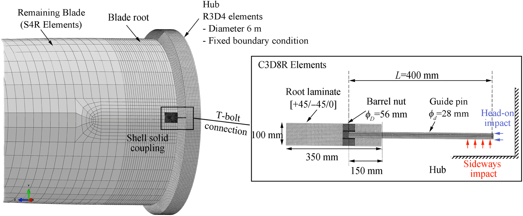 Figure 9 Finite element modelling of guide pin impact with hub for sideways and head-on impact scenarios
A simplified structural representation of hub is considered for impact assessment. The hub is defined as a rigid body, discretised with four noded bilinear (R3D4) elements, and is constrained in all degrees of freedom. General contact attribute together with suitable tangential and mechanical interaction properties available in Abaqus/explicit is used to define contact between impact surface of the guide pin and hub. For the case of sideways' impact, the initial impact surface is transverse to the guide pin (red arrows, Figure 9), whereas for head-on impact, the initial impact surface is along its axial direction (blue arrows, Figure 9). Maximum stress failure criterion is used as failure prediction model for root laminate, whereas von-Mises equivalent plastic strain criterion is used for damage assessment at barrel nut and guide pin. The details of these criteria along with corresponding material properties can also be found in Verma et al. (2019a, 2020).
It is to be noted that the structural coordinate system for finite element analysis is different from the ones used in HAWC2 simulation. The sideways' impact corresponds to initial impact velocity in x-direction of structural coordinate system ($ {V}_x^{\mathrm{fem}} $) whereas head-on impact represents impact velocity in z-direction of structural coordinate system ($ {V}_z^{\mathrm{fem}} $). Impact velocities in the range of $ 0.1\le \left[{V}_x^{\mathrm{fem}},{V}_z^{\mathrm{fem}}\right]\le 2\mathrm{m}/\mathrm{s} $ are used for impact assessment for sideways and head-on scenarios.
4 Results and Discussion
In this section, response time histories, spectral densities and corresponding standard deviations are considered for discussing the effect of wind-wave misalignment on the wind turbine blade mating process. First, an individual description of hub-centre and blade root motions are presented, followed by discussion of impact velocity between root and hub for different wind-wave misalignment. Then, the damage assessment results for blade root impact with hub are discussed, where allowable impact velocities for sideways and head-on impact scenarios are estimated. Finally, a safe domain for performing mating task under different wind-wave misalignment conditions is compared.
4.1 Hub Motions
Figure 10a and b present the time histories of hub-centre displacement in side-side ($ {U}_x^{\mathrm{hub}} $) and fore-aft ($ {U}_y^{\mathrm{hub}} $) directions for mating process in an environmental condition with Hs = 2.5m, Tp = 4s, Uw = 10m/s and different wind-wave misalignments (βwave = 0°, 30°, 60° and 90°). It can be clearly seen that the motion of hub in side-side direction ($ {U}_x^{\mathrm{hub}} $) is highest for largest degree of misalignment (βwave = 90°), with amplitude of responses further decreasing with shift in degree of misalignment. It is further observed that the motion of hub-centre in side-side direction ($ {U}_x^{\mathrm{hub}} $) is negligible for load case with completely aligned wind-wave condition (βwave = 0°); see Figure 10a. On the contrary, the motion of hub-centre in fore-aft direction ($ {U}_y^{\mathrm{hub}} $) is largest for load case with βwave = 0° condition (see Figure 10b), and reduces with increasing degree of misalignment. For βwave = 90°, the motion of hub-centre in fore-aft direction is found insignificant.
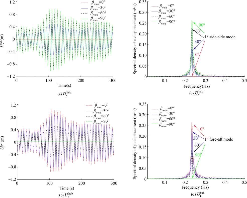 Figure 10 Response time histories and spectral density curve for load case Hs = 2.5 m, Tp = 4 s, Uw = 10 m/s and for βwave = 0°, 30°, 60°, and 90°
The same observation is also described through Figure 10c and d where spectral density curves for $ {U}_x^{\mathrm{hub}} $ and $ {U}_y^{\mathrm{hub}} $ are compared for Hs = 2.5m, Tp = 4s, Uw = 10m/s and different wind-wave misalignment (βwave = 0°, 30°, 60° and 90°). Given that the eigen period of the monopile structure in the first fore-aft and side-side bending modes is approximately 4.25 s, the load case with Tp = 4s causes resonance-induced amplification of responses, and thus, the highest peak of frequency is observed at approximately 0.23 Hz. The frequency peak corresponding to the monopile's first side-side mode is maximum for largest degree of misalignment (βwave = 90°), whereas the frequency peak corresponding to the monopile's first fore-aft mode is maximum for aligned wind-wave condition (βwave = 0°).
Figure 11a–b present the motion of hub-centre in xy-plane for mating process in different wind-wave misalignment condition (βwave = 0°, 30°, 60° and 90°) and two Tp (Tp = 4s and Tp = 6s). As expected, for both the values of Tp, the motion of hub-centre for βwave = 0° is concentrated explicitly in fore-aft direction ($ {U}_y^{\mathrm{hub}} $), whereas motion of hub-centre for βwave = 90° is concentrated solely in side-side direction ($ {U}_x^{\mathrm{hub}} $).
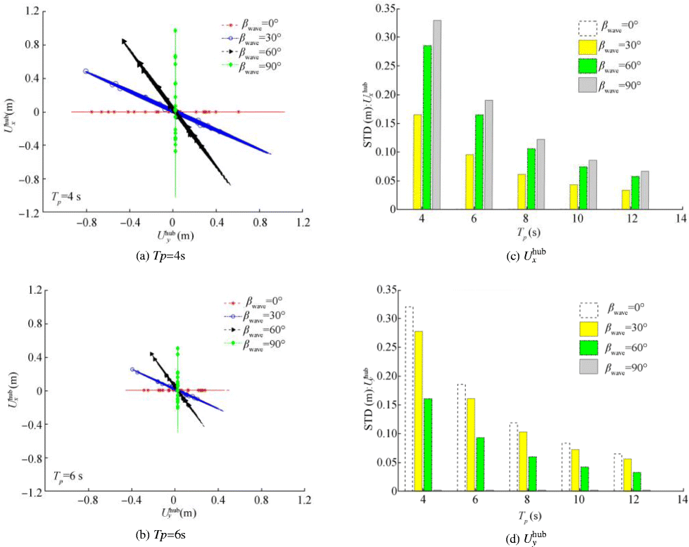 Figure 11 Motion of hub-centre in xy-plane and comparison of standard deviations for load case Hs = 2.5 m, Tp = 4 s, 6 s, 8 s, 10s, 12 s, Uw = 10 m/s and βwave = 0°, 30°, 60° and 90°
However, it is observed that for βwave = 30°, 60°, the motions of hub-centre in fore-aft and side-side directions are correlated. It is to be also noted that the motion of hub-centre in xy-plane is substantially high for Tp = 4s, which nears the eigen period of the monopile structure in both side-side and fore-aft bending mode. On the other hand, for Tp = 6s, the motion of hub-centre in xy plane is reduced by more than 40%, given that the wave frequency is away from the excitation frequency of the monopile structure.
A comparison between the standard deviation of $ {U}_x^{\mathrm{hub}} $ and $ {U}_y^{\mathrm{hub}} $ for mating process in varying wind-wave misalignments (βwave = 0°, 30°, 60° and 90°) and varying values of Tp (Tp = 4s, 6s, 8s, 10s, 12s) is also presented in Figure 11c–d. It is clearly observed that the standard deviation for both $ {U}_x^{\mathrm{hub}} $ and $ {U}_y^{\mathrm{hub}} $, is highest for Tp = 4s, and further reduces with increasing values of Tp for all degrees of misalignments. This is because of the shift in wave spectral peak period away from the eigen period of the monopile structure. Also, for a given Tp, standard deviation of $ {U}_x^{\mathrm{hub}} $ is largest for βwave = 90°, and smallest for βwave = 0°, whereas standard deviation of $ {U}_y^{\mathrm{hub}} $ is highest for βwave = 0°, and least for βwave = 90°.
4.2 Blade Root Motions
Figure 12a presents the displacement of blade root in global x- and y-direction of the installation system for environmental condition with Uw = 10m/s. The blade root responses in y-direction are dominant compared with its motion in x-direction which is negligible. This is due to the action of tugger lines which constrains the blade root motions in x-direction. Figure 12b presents the spectral density curve for the blade root displacement in global y-direction, where peak frequency is observed at approximately 0.08Hz, and corresponds to fr1.
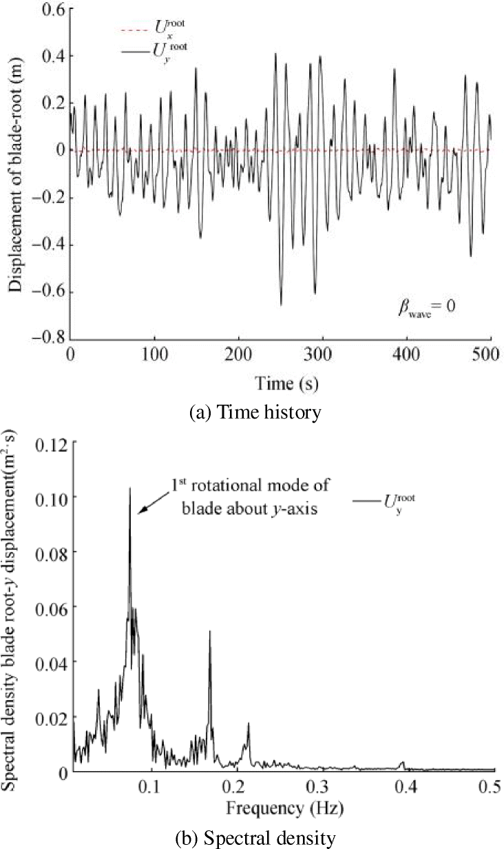 Figure 12 Blade root responses for Uw = 10 m/s
4.3 Impact Velocity Between Blade Root and Hub
Figure 13a–b present the impact velocity between blade root and hub in side-side ($ {V}_x^{\mathrm{imp}} $) and fore-aft ($ {V}_y^{\mathrm{imp}} $) direction for mating process in an environmental condition with Hs = 2.5m, Tp = 4s, Uw = 10m/s and different wind-wave misalignments (βwave = 0°, 30°, 60° and 90°). It can be seen that the impact velocity in the side-side direction ($ {V}_x^{\mathrm{imp}} $) is highest for βwave = 90° with maximum response reaching a value of more than 1.5 m/s. Furthermore, the amplitude of $ {V}_x^{\mathrm{imp}} $ reduces with decrease in the degree of misalignment, with negligible response for aligned wind-wave conditions (βwave = 0°). Since impact velocity in the side-side direction ($ {V}_x^{\mathrm{imp}} $) is dominant for large wind-wave misalignments, this implies that head-on impact scenarios can occur between blade root and hub for such cases. On the contrary, impact velocity in the fore-aft direction ($ {V}_y^{\mathrm{imp}} $) is highest for aligned wind-wave condition (βwave = 0°), and reduces with further increase in misalignment. Therefore, aligned wind-wave condition can cause sideways impact of the blade root guide pin with the hub. Also, there are acceptable responses for $ {V}_y^{\mathrm{imp}} $ for load case with βwave = 90° because of contribution from blade root responses in the fore-aft direction.
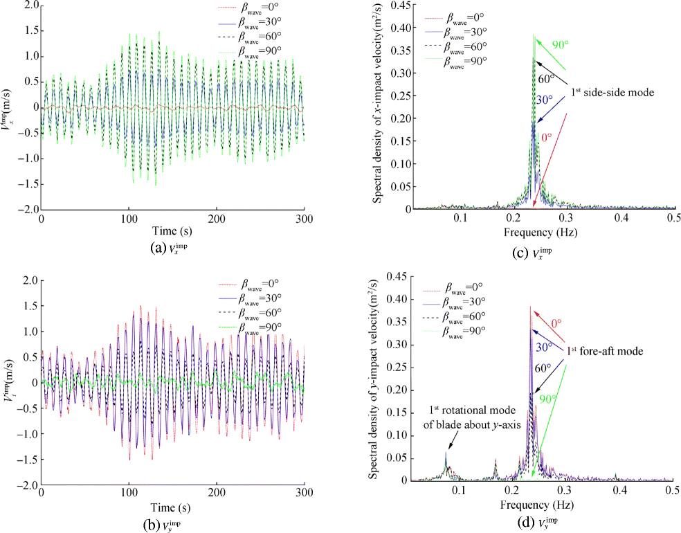 Figure 13 Response time histories and spectral density curve for load case Hs = 2.5 m, Tp = 4 s, Uw = 10 m/s and for different wind-wave misalignment βwave = 0°, 30°, 60° and 90°
Figure 13 c–d present the spectral density curve for $ {V}_x^{\mathrm{imp}} $ and $ {V}_y^{\mathrm{imp}} $ for mating process in an environmental condition with Hs = 2.5m, Tp = 4s, Uw = 10m/s and different wind-wave misalignments (βwave = 0°, 30°, 60° and 90°). As observed before, the spectral density for $ {V}_x^{\mathrm{imp}} $ has highest frequency peak observed for βwave = 90°, whereas spectral density for $ {V}_y^{\mathrm{imp}} $ has highest frequency peak observed for βwave = 0°. It can also be seen in Figure 13d that there is no contribution of hub response towards $ {V}_y^{\mathrm{imp}} $ for βwave = 90°; however, there is contribution of frequency peak corresponding to the blade root responses. Note that there are two peaks observed for spectral density curves corresponding to impact velocity in fore-aft direction ($ {V}_y^{\mathrm{imp}} $). First peak corresponds to the first rotational mode of the blade about global y-axis (0.08Hz), whereas the other peak corresponds to eigen frequency of the monopile in the first fore-aft mode (0.23Hz).
On the other hand, there is only one frequency peak observed for $ {V}_x^{\mathrm{imp}} $, which corresponds to eigen frequency of monopile in first side-side mode. Here, no frequency peak is observed for blade root motions. This is because in this study, wind is considered acting from the fore-aft direction of the installation system.
Figure 14a–b present the standard deviation of $ {V}_x^{\mathrm{imp}} $ and $ {V}_y^{\mathrm{imp}} $ for mating process in an environmental condition corresponding to Hs = 2.5m, Uw = 10m/s, wind-wave misalignments (βwave = 0°, 30°, 60° and 90°) and varying values of Tp (Tp = 4s, 6s, 8s, 10s, 12s). It is seen that the standard deviation for both $ {V}_x^{\mathrm{imp}} $ and $ {V}_y^{\mathrm{imp}} $ reduces with increasing values of Tp, with highest standard deviation obtained for Tp = 4s. Also, for a given Tp, standard deviation for $ {V}_x^{\mathrm{imp}} $ is highest for βwave = 90°, whereas standard deviation for $ {V}_y^{\mathrm{imp}} $ is largest for βwave = 0°. Furthermore, as discussed, there are acceptable responses for $ {V}_y^{\mathrm{imp}} $ for βwave = 90° and have the same standard deviations for all values of Tp. This is because there is no contribution of hub responses for βwave = 90°, and all results correspond to the blade root responses at Uw = 10m/s. Therefore, for βwave = 90°, $ {V}_y^{\mathrm{imp}} $ is completely dominated by blade root motions.
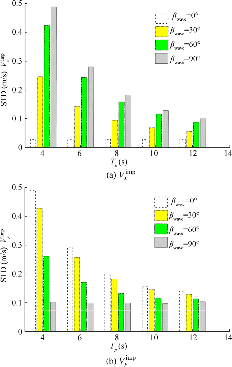 Figure 14 Comparison of standard deviations for load case Hs = 2.5 m, Tp = 4 s, 6 s, 8 s, 10s, 12 s, Uw = 10 m/s and for different wind-wave misalignment βwave = 0°, 30°, 60° and 90°
4.4 Damage Assessment at the Blade Root
In this section, allowable impact velocities are evaluated for head-on ($ {V}_x^{\mathrm{allow}} $), and sideways ($ {V}_y^{\mathrm{allow}} $) impact scenarios, based on which structural safety assessment of mating task will be performed for different sea states. Impact velocities in the range of $ 0.1\ \mathrm{m}/\mathrm{s}\le \left[{V}_x^{\mathrm{fem}},{V}_z^{\mathrm{fem}}\right]\le 2\ \mathrm{m}/\mathrm{s} $ are considered for impact assessment. Figure 15a–b present $ {I}_f^z\left({S}_{33}\right) $ obtained for different impact velocities corresponding to sideways and head-on impact scenarios, respectively. It can be seen that for sideways scenario, impact velocity above 0.76 m/s causes $ {I}_f^z(S33)\ge 1 $, and thus, 0.76 m/s is considered as allowable impact velocity in fore-aft direction ($ {V}_y^{\mathrm{allow}}=0.76\mathrm{m}/\mathrm{s} $). On the other hand, for head-on impact scenario, impact velocity above 1.35 m/s causes $ {I}_f^z\left({S}_{33}\right)\ge 1 $, and thus, 1.35 m/s is considered as allowable impact velocity in side-side direction ($ {V}_x^{\mathrm{allow}}=1.35\mathrm{m}/\mathrm{s} $). This clearly implies that the sideways' impact scenario, developed largely due to aligned wind-wave condition, is more critical compared with head-on impact scenarios, given that failure in the root laminate is achieved at relatively less impact velocity. The reason for this is that sideways' impact scenario involves impact loads along the transverse direction of the guide pin (see Figure 15a), causing its inelastic bending at low impact velocity. On the other hand, for the case of head-on impact, impact loads are caused in the axial direction of guide pin bolt (see Figure 15b), where the bolt has high strength and stiffness, and are designed to take operational loads.
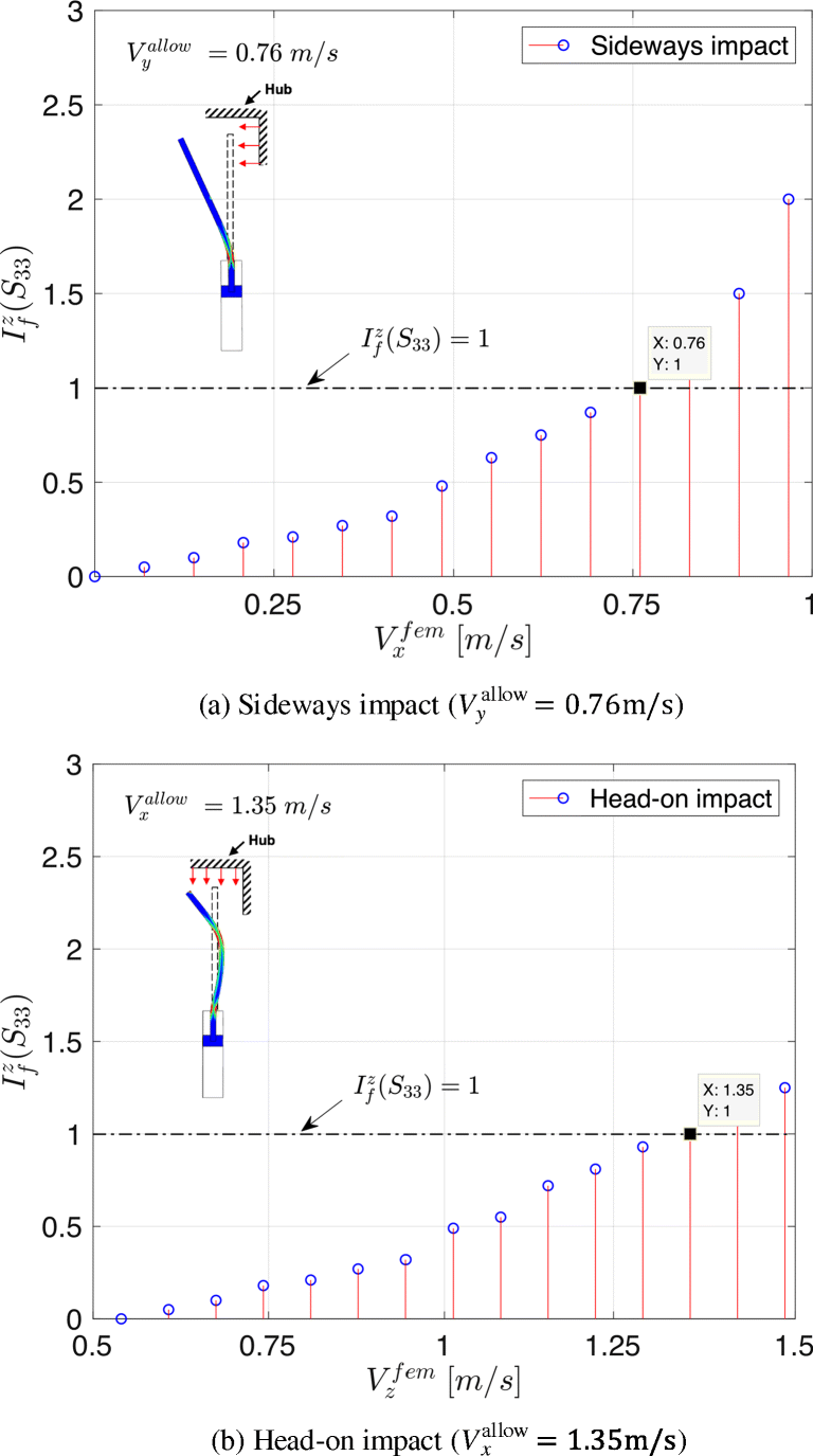 Figure 15 Allowable impact velocities
Furthermore, failure mode consists of s-shape buckling of guide pin, and the failure in the laminate is developed at a large impact velocity. A comparison of the failure modes obtained at the blade root for sideways and head-on impact scenarios above the threshold level is presented in Figure 16. Here, the results for sideways' impact correspond to $ {V}_x^{\mathrm{fem}}=0.85\mathrm{m}/\mathrm{s} $, and head-on impact corresponds to $ {V}_z^{\mathrm{fem}}=1.45\mathrm{m}/\mathrm{s} $.
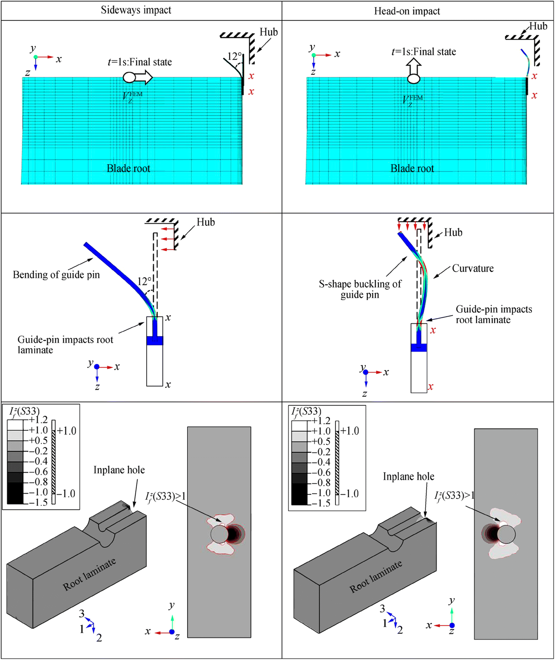 Figure 16 Comparison of failure modes for impact in sideways and head-on impact scenarios
It can be clearly seen that the impact of the blade root in the sideways direction causes bending of guide pin with an angle of approximately 12°. On the contrary, impact in the head-on direction causes s-shape buckling of guide pin. Furthermore, due to these failure modes in the form of inelastic deformation, guide pin impacts the root laminate near the inplane hole for both the scenarios, and thus, transverse through-the-thickness normal tensile stresses are induced at the critical location z of the blade root. These are represented by stress exposure factors coloured in white fringes and correspond to failure index at location z more than 1 ($ {I}_f^z\left({S}_{33}\right) \gt 1 $). Also, note that the stress exposure factors corresponding to transverse through-the-thickness compressive stresses ($ {I}_f^z\left({S}_{33}\right) \lt 0 $) are also developed near the inplane hole, however are not comparatively that critical for development of delamination at this region. Furthermore, these stresses are developed in two different and opposite corners of the inplane hole, for sideways and head-on impact scenarios. The reason for this is that for sideways' impact scenarios, guide pin impacts the inplane hole along the direction of the bend, whereas for head-on impact, guide pin deforms in s-shape and impacts the inplane hole in the direction of its buckled curvature.
4.5 Structural Safety Assessment of Mating Task for Sea States with Given Wind-Wave Misalignment
In this section, structural safety assessment of blade mating task will be assessed for load cases with different wind-wave misalignment conditions and corresponding safe domain for the installation task will be compared. First, extreme value distributions and corresponding characteristic extreme responses are obtained for impact velocities in fore-aft and side-side direction. Then, these characteristic values are compared with their allowable impact velocities, and only those sea states are considered safe for mating task for which the characteristic values are less than the allowable responses.
Figure 17a–b present the Gumbel fitting of extreme responses for impact velocities in side-side ($ {V}_x^{\mathrm{imp}} $) and fore-aft direction ($ {V}_y^{\mathrm{imp}} $), respectively, for load cases with Hs = 2.5m, Tp = 4s, Uw = 10m/s and different wind-wave misalignments (βwave = 0°, 30°, 60° and 90°). Each load case consists of 20 seeds, where maximum values are extracted from the time series of impact velocities and are plotted in the Gumbel probability paper. Overall, there are 20 data points used for each load case.
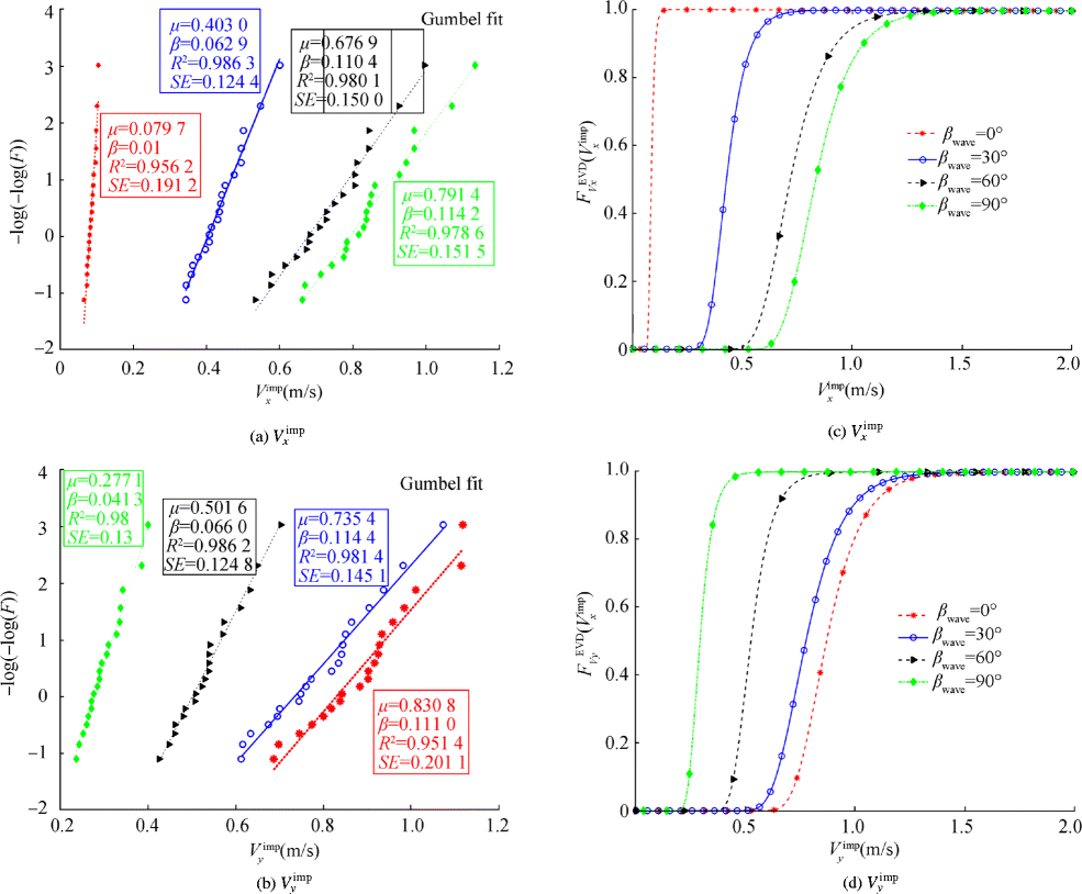 Figure 17 Gumbel fitting of extreme responses and corresponding extreme value distribution for load case Hs = 2.5 m, Tp = 4 s, Uw = 10 m/s and βwave = 0°, 30°, 60° and 90°
It can be clearly seen that the data points describing the extreme values of $ {V}_x^{\mathrm{imp}} $ and $ {V}_y^{\mathrm{imp}} $ fit the Gumbel plot satisfactorily for all the load cases. It is worth mentioning that the data points were also fitted to probability papers of other distributions such as Lognormal, Weibull and Exponential to check the best fit. It was found that Gumbel distribution provides the best coefficient of determination (R2) and least standard error (SE).
Furthermore, the parameters μ and β, which describe the Gumbel distribution, are estimated and are explicitly mentioned next to the fitted line for load cases with different wind-wave misalignment (see Figure 17a and b) together with the corresponding R2 and SE values. Note that the cumulative distribution function of Gumbel distribution is given by (F(Vimp) = exp(− exp(−(Vimp − μ)/β))) where μ and β are location and scale parameters, respectively. It can also be observed that the location parameter (μ) for $ {V}_x^{\mathrm{imp}} $ is largest for βwave = 90° and reduces further with reduction in degree of misalignment. On the other hand, location parameter (μ) for $ {V}_y^{\mathrm{imp}} $ is largest for βwave = 0° and reduces with increase in misalignment. Similar Gumbel fitting of extreme responses and corresponding Gumbel parameters for $ {V}_x^{\mathrm{imp}} $ and $ {V}_y^{\mathrm{imp}} $ were estimated for every environment conditions examined in the present study.
Extreme value distributions for $ {V}_x^{\mathrm{imp}} $ and $ {V}_y^{\mathrm{imp}} $ are described using the values of the estimated parameters (μ and β) in Figure 17c and d, respectively, for load cases with Hs = 2.5m, Tp = 4s, Uw = 10m/s and different wind-wave misalignments (βwave = 0°, 30°, 60° and 90°). It is clearly observed that the extreme value distribution for $ {V}_x^{\mathrm{imp}} $ on the rightmost side corresponds to the load case with βwave = 90°, whereas the distribution on the leftmost side corresponds to βwave = 0°. This result is in line with the previous observations where impact velocity in the side-side direction was found largest for misaligned wind-wave conditions. Similarly, extreme value distribution for $ {V}_y^{\mathrm{imp}} $ is located on the rightmost side for aligned wind-wave condition (βwave = 0°).
Figure 18a–b present the characteristic extreme responses for impact velocities in side-side ($ {V}_x^{\mathrm{char}} $) and fore-aft directions ($ {V}_y^{\mathrm{char}} $), respectively, for load cases with Hs = 2.5m, Tp = 6s, Uw = 10m/s and different wind-wave misalignments (βwave = 0°, 30°, 60° and 90°). These values are obtained using extreme value distributions and correspond to a target exceedance level of 10−2. Note that a black-dotted line is also presented in the figures to represent 10−2 exceedance level, and the point where it intersects the curve corresponds to the characteristic extreme responses for different load cases. It can be seen that $ {V}_x^{\mathrm{char}} $ is largest for βwave = 90°, with the value reaching approximately 1.30 m/s. Furthermore, this value decreases with shift in the degree of misalignment and is lowest for βwave = 0°.
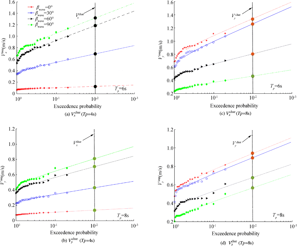 Figure 18 Characteristic extreme responses for load case: Hs = 2.5 m, Uw = 10 m/s and for βwave = 0°, 30°, 60° and 90°
On the contrary, $ {V}_y^{\mathrm{char}} $ is highest for βwave = 0° and least for βwave = 90°. Similar results are obtained in Figure 18c–d, where $ {V}_x^{\mathrm{char}} $ and $ {V}_y^{\mathrm{char}} $ are evaluated for load case with Hs = 2.5m, Uw = 10m/s, different wind-wave misalignments (βwave = 0°, 30°, 60° and 90°) and with Tp = 8s.
Finally, in order to decide whether the sea state with a given wind-wave misalignment is safe or not for mating task, it is required to compare the characteristic extreme responses in both side-side and fore-aft directions with allowable impact velocities. Only those sea states are considered safe for which $ {V}_x^{\mathrm{char}} $ and $ {V}_y^{\mathrm{char}} $ are less than their corresponding impact velocities. The $ {V}_x^{\mathrm{char}} $ and $ {V}_y^{\mathrm{char}} $ presented in Figure 18a–b for the load case with Hs = 2.5m, Tp = 6s, Uw = 10m/s and different wind-wave misalignments (βwave = 0°, 30°, 60° and 90°) are compared with corresponding $ {V}_x^{\mathrm{allow}}=1.35\mathrm{m}/\mathrm{s} $ and $ {V}_y^{\mathrm{allow}}=0.76\mathrm{m}/\mathrm{s} $, respectively. Note that the characteristic extreme responses for which the values are less than the allowable responses are marked as green dots (on the dotted black line), and for those in which the characteristic responses are larger than allowable values are marked as red dots (Figure 18a–b).
It can be seen that for the case of $ {V}_x^{\mathrm{char}} $, all load cases with wind-wave misalignments are marked as green dots, given that the characteristic responses for all the misalignments are less than $ {V}_x^{\mathrm{allow}}=1.35\mathrm{m}/\mathrm{s} $. However, for $ {V}_y^{\mathrm{char}} $, only the load case with βwave = 90° is marked as a green dot as the characteristic responses are less than $ {V}_y^{\mathrm{allow}}=0.76\mathrm{m}/\mathrm{s} $. The characteristic responses corresponding to βwave = 0°, 30°, 60° are larger than $ {V}_y^{\mathrm{allow}}=0.76\mathrm{m}/\mathrm{s} $ and are hence marked as red dots. This implies that for the load case Hs = 2.5m, Tp = 6s, Uw = 10m/s, only βwave = 90° belongs to the safe domain of sea state for the mating task. Also, Figure 18 c–d show the similar comparison for the load case with Tp = 8s, and it is found that for the case of $ {V}_x^{\mathrm{char}} $, all misalignments are marked as green dots but for $ {V}_y^{\mathrm{char}} $, only βwave = 60°, 90° are marked as green dots. Note that only those sea states are considered safe for which both $ {V}_x^{\mathrm{char}} $ and $ {V}_y^{\mathrm{char}} $ are less than $ {V}_x^{\mathrm{allow}} $ and $ {V}_y^{\mathrm{allow}} $, respectively. Therefore, for the load case Hs = 2.5m, Tp = 8s, Uw = 10m/s, only βwave = 60° and 90° belong to the safe domain.
Similar calculation for safety assessment is performed for all the load cases considered in this paper, i.e. Hs in the range 1m ≤ Hs ≤ 3m, Tp in the range 4s ≤ Tp ≤ 12s, Uw = 10m/s and different wind-wave misalignments (βwave = 0°, 30°, 60° and 90°). Figure 19 presents the comparison between different safe domains analysed for considered wind-wave misalignments. Note that the area lying below the line corresponding to a particular wind-wave misalignment is considered safe for the mating task. It can be clearly seen that the collinear wind-wave condition has the least percentage of safe domain, whereas βwave = 90° has highest percentage of safe sea states for the mating task. This is because of the fact that aligned wind-wave conditions cause sideways' impact that are critical and cause damages to the root laminate at relatively less impact velocity. Overall, it can be said that, although both, aligned and misaligned wind-wave conditions can induce large responses between root and hub during the blade mating process; it is the aligned wind-wave conditions that are the most critical as far as the structural safety of the blade root mating process is concerned.
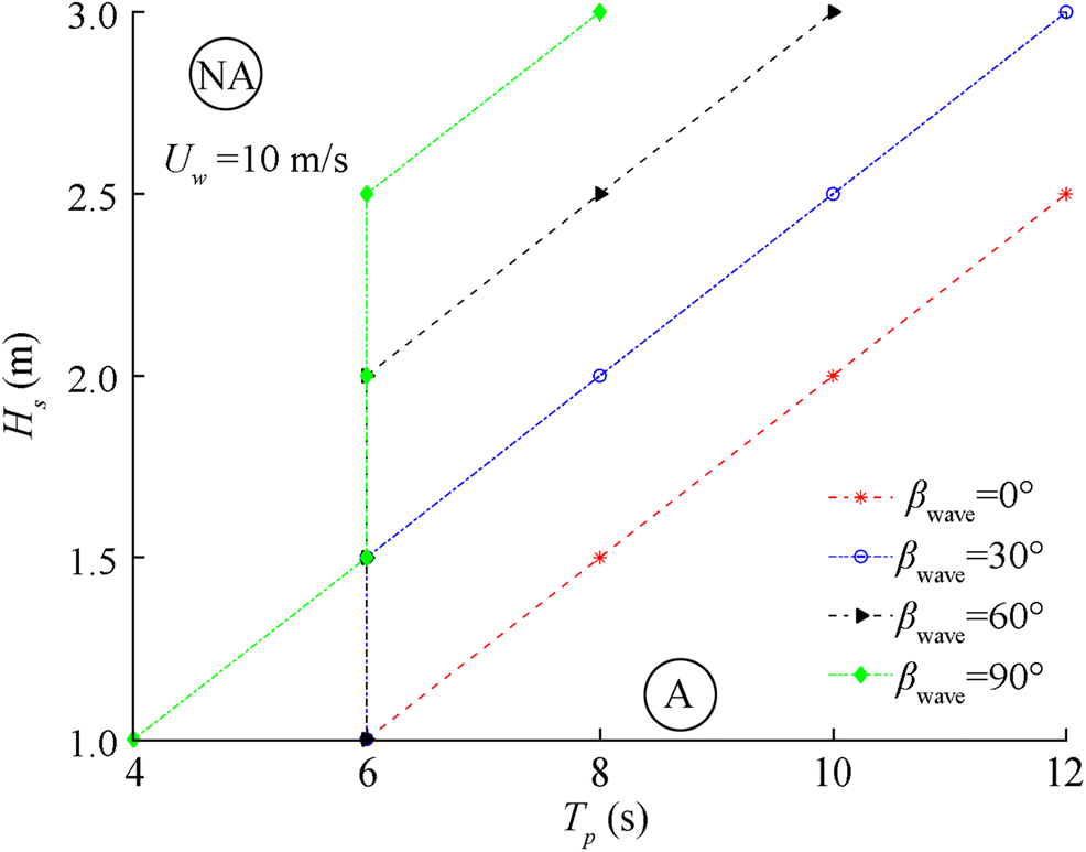 Figure 19 Comparison of safe domain for different wind-wave misalignment
5 Conclusion
The present paper investigated the effects of wind-wave misalignment on the wind turbine blade mating process. Three distinct response parameters: (1) impact velocity between root and hub during mating, (2) impact-induced damages at the blade root and (3) safety assessment of the mating task for a given wind-wave misalignment condition, were considered for discussion. The mating process was numerically modelled in HAWC2 numerical code, and time domain analyses were performed for load cases representing environmental conditions for the North Sea centre. Four cases of wind-wave misalignments (βwave = 0°, 30°, 60° and 90°) were considered for each load case. Additionally, the impact scenarios—sideways and head-on impact of the guide pin with the hub—were also numerically modelled using Abaqus/explicit, and corresponding allowable impact velocities in the fore-aft and side-side directions were obtained. The following are the main conclusions from this study:
1) The displacement of the hub-centre in the side-side mode ($ {U}_x^{\mathrm{hub}} $) is highest for load cases with largest wind-wave misalignment (βwave = 90°), and it further reduces with shift in the degree of misalignment. On the other hand, displacement of the hub-centre in the fore-aft direction ($ {U}_y^{\mathrm{hub}} $) is largest for aligned wind-wave cases (βwave = 0°), and the amplitude of responses reduces with increase in misalignment.
2) The load cases with largest degree of wind-wave misalignment have the largest impact velocity in the side-side direction, and thus for such cases, head-on impact between guide pin and hub are dominant. On the contrary, aligned wind-wave cases induce largest impact velocity in the fore-aft direction, and thus cause impact of the guide pin with the hub in sideways scenario.
3) The sideways' impact of the guide pin with hub is more critical than the head-on impact, and the failure criteria in the root laminate are met at a relatively low velocity of impact. This is because sideways' impact scenario involves impact loads along the transverse direction of the guide pin causing bending of the bolt. On the other hand, for the case of head-on impact, impact loads are caused in the axial direction of guide pin, where the bolt has high strength and stiffness. This causes impact-induced buckling of guide pin, but at a large impact energy. Therefore, impact scenarios for aligned wind-wave conditions are more critical for the wind turbine blade mating process.
4) The safety assessment of the mating task was also compared for load cases with different wind-wave misalignment conditions. It was found that βwave = 90° has the largest domain for safe installation of wind turbine blades, which reduces with shift in the degree of misalignment. Also, for collinear wind-wave condition (βwave = 0°), lowest percentage of safe domain for mating task was obtained. The reason for this is that aligned wind-wave conditions cause sideways impact, which, from a structural perspective, is more critical than a head-on impact scenario, developed due to misaligned wind-wave conditions.
-
Figure 1 Blade root mating process (https://orsted.com/en) (https://vessels.offshorewind.biz/vessels/sea challenger) (https://www.siemens.com)
Figure 2 Different wind and wave directions (wind and wave direction corresponds to a compass—0° represents East, 90° North, 180° West and 270° represents South)
Figure 3 Illustration of impact scenarios during the blade mating process
Figure 4 Position of interest at the blade root for assessment
Figure 5 Analysis procedure considered in this study
Figure 6 Description of numerical modelling of installation system
Figure 7 Histogram data at North Sea centre
Figure 8 Bird view of mating process with considered wind-wave misalignment
Figure 9 Finite element modelling of guide pin impact with hub for sideways and head-on impact scenarios
Figure 10 Response time histories and spectral density curve for load case Hs = 2.5 m, Tp = 4 s, Uw = 10 m/s and for βwave = 0°, 30°, 60°, and 90°
Figure 11 Motion of hub-centre in xy-plane and comparison of standard deviations for load case Hs = 2.5 m, Tp = 4 s, 6 s, 8 s, 10s, 12 s, Uw = 10 m/s and βwave = 0°, 30°, 60° and 90°
Figure 12 Blade root responses for Uw = 10 m/s
Figure 13 Response time histories and spectral density curve for load case Hs = 2.5 m, Tp = 4 s, Uw = 10 m/s and for different wind-wave misalignment βwave = 0°, 30°, 60° and 90°
Figure 14 Comparison of standard deviations for load case Hs = 2.5 m, Tp = 4 s, 6 s, 8 s, 10s, 12 s, Uw = 10 m/s and for different wind-wave misalignment βwave = 0°, 30°, 60° and 90°
Figure 15 Allowable impact velocities
Figure 16 Comparison of failure modes for impact in sideways and head-on impact scenarios
Figure 17 Gumbel fitting of extreme responses and corresponding extreme value distribution for load case Hs = 2.5 m, Tp = 4 s, Uw = 10 m/s and βwave = 0°, 30°, 60° and 90°
Figure 18 Characteristic extreme responses for load case: Hs = 2.5 m, Uw = 10 m/s and for βwave = 0°, 30°, 60° and 90°
Figure 19 Comparison of safe domain for different wind-wave misalignment
Table 1 Modelling parameters of installation system used in HAWC2
Parameter Values Diameter of monopile (m) 9 Pile penetrating depth (m) 45 Water depth (m) 30 Eigen period - first fore-aft mode (s) 4.2 Damping ratio - first fore-aft mode (%) 1 Blade mass (t) 41.7 Blade length (m) 86.4 Blade root diameter (m) 5.4 Yoke weight (t) 50 Table 2 Description of environmental load cases
EC βwave (°) Hs (m) Tp (s) Uw (m/s) TI 1 0 1, 1.5, ....3.0 4, 6, ...12 10 0.12 2 30 1, 1.5, ....3.0 4, 6, ...12 10 0.12 3 60 1, 1.5, ....3.0 4, 6, ...12 10 0.12 4 90 1, 1.5, ....3.0 4, 6, ...12 10 0.12 -
Bachynski EE, Kvittem MI, Luan C, Moan T (2014) Wind-wave misalignment effects on floating wind turbines: motions and tower load effects. Journal of Offshore Mechanics and Arctic Engineering 136(4): 041902. https://doi.org/10.1115/1.4028028 Bak C, Zahle F, Bitsche R, Kim T, Yde A, Henriksen LC, Hansen MH, Natarajan A (2013) Description of the DTU 10 MW reference wind turbine, Progress report, Report-I-0092, DTU Wind Energy Barj L, Jonkman JM, Robertson A, Stewart GM, Lackner MA, Haid L, Matha D, Stewart SW (2014) Wind/wave misalignment in the loads analysis of a floating offshore wind turbine, in: 32nd ASME Wind Energy Symposium: 0363. https://doi.org/10.2514/6.2014-0363 Brøndsted P, Nijssen RP (2013) Advances in wind turbine blade design and materials. Elsevier Fischer T, Rainey P, Bossanyi E, Kuhn M (2011) Study on control concepts suitable for mitigation of loads from misaligned wind and waves on offshore wind turbines supported on monopiles. Wind Eng 35(5): 561–573. https://doi.org/10.1260/0309-524X.35.5.561 Hibbitt H, Karlsson B, Sorensen P (2016) Abaqus analysis users' manual IEC (2005) International standard 61400-1, wind turbines, part 1: design requirements Jiang Z (2018) The impact of a passive tuned mass damper on offshore single-blade installation. J Wind Eng Ind Aerodyn 176:65–77. https://doi.org/10.1016/j.jweia.2018.03.008 Jiang Z, Gao Z, Ren Z, Li Y, Duan L (2018) A parametric study on the blade final installation process for monopile wind turbines under rough environmental conditions. Eng Struct 172:1042–1056. https://doi.org/10.1016/j.engstruct.2018.04.078 Ketele S (2013) Detailed modeling of connections in large composite wind turbine blades. Master's thesis, Universiteit Gent Larsen TJ, Hansen AM (2007) How 2 HAWC2, the user's manual, Tech. rep., Risø National Laboratory Li L, Gao Z, Moan T (2015) Joint distribution of environmental condition at five European offshore sites for design of combined wind and wave energy devices. Journal of Offshore Mechanics and Arctic Engineering 137(3): 031901. https://doi.org/10.1115/1.4029842 Mann J (1994) The spatial structure of neutral atmospheric surface-layer turbulence. J Fluid Mech 273:141–168. https://doi.org/10.1017/S0022112094001886 Martınez V, Guemes A, Trias D, Blanco N (2011) Numerical and experimental analysis of stresses and failure in t-bolt joints. Compos Struct 93(10): 2636–2645. https://doi.org/10.1016/j.compstruct.2011.04.031 Molla IG (2015) Installing a blade in a wind turbine and wind turbines, US Patent App. 14/657, 307 Morison J, Johnson J, Schaaf S et al (1950) The force exerted by surface waves on piles. J Pet Technol 2(05): 149–154. https://doi.org/10.2118/950149-G Ren Z, Jiang Z, Skjetne R, Gao Z (2018a) Development and application of a simulator for offshore wind turbine blades installation. Ocean Eng 166:380–395. https://doi.org/10.1016/j.oceaneng.2018.05.011 Ren Z, Skjetne R, Gao Z et al (2018b) A crane overload protection controller for blade lifting operation based on model predictive control. Energies 12(1): 1–22. https://doi.org/10.3390/en12010050 Ren Z, Skjetne R, Jiang Z, Gao Z, Verma AS (2019) Integrated GNSS/IMU hub motion estimator for offshore wind turbine blade installation. Mech Syst Signal Process 123:222–243. https://doi.org/10.1016/j.ymssp.2019.01.008 Van Vledder GP (2013) On wind-wave misalignment, directional spreading and wave loads, in: ASME 2013 32nd International Conference on Ocean, Offshore and Arctic Engineering, American Society of Mechanical Engineers: V005T06A087–V005T06A087. https://doi.org/10.1115/OMAE2013-11393 Velarde J (2016) Design of monopile foundations to support the DTU 10 MW offshore wind turbine, Master's thesis, Norwegian University of Science and Technology (NTNU), Trondheim Verma AS, Vedvik NP and Gao Z (2017) December. Numerical assessment of wind turbine blade damage due to contact/impact with tower during installation. In IOP Conference Series: Materials Science and Engineering. 276(1): 012–025 https://doi.org/10.1088/1757-899X/276/1/012025 Verma AS, Jiang Z, Vedvik NP, Gao Z, Ren Z (2019a) Impact assessment of a wind turbine blade root during an offshore mating process. Eng Struct 180:205–222. https://doi.org/10.1016/j.engstruct.2018.11.012 Verma AS, Vedvik NP, Gao Z (2019b) A comprehensive numerical investigation of the impact behaviour of an offshore wind turbine blade due to impact loads during installation. Ocean Eng 172:127–145. https://doi.org/10.1016/j.oceaneng.2018.11.021 Verma AS, Gao Z, Jiang Z, Zhengru R, Vedvik NP (2019c) Structural safety assessment of marine operations from a long term perspective: a case study of offshore wind turbine blade installation, 38th International Conference on Ocean, Offshore and Arctic Engineering OMAE https://doi.org/10.1115/OMAE2019-96686 Verma AS, Jiang Z, Ren Z, Gao Z, Vedvik NP (2019d) Response-based assessment of operational limits for mating blades on monopile-type offshore wind turbines. Energies 12(10): 1867. https://doi.org/10.3390/en12101867 Verma AS, Vedvik NP, Haselbach PU, Gao Z, Jiang Z (2019e) Comparison of numerical modelling techniques for impact investigation on a wind turbine blade. Compos Struct 209: 856–878. https://doi.org/10.1016/j.compstruct.2018.11.001 Verma, A.S., Zhao, Y., Gao, Z. and Vedvik, N.P., (2019f). Explicit structural response-based methodology for assessment of operational limits for single blade installation for offshore wind turbines. In Proceedings of the Fourth International Conference in Ocean Engineering (ICOE2018) (pp. 737–750). Springer, Singapore. https://doi.org/10.1007/978-981-13-3134-3_55 Verma AS, Jiang Z, Gao Z, Vedvik NP (2020a) Effects of passive tuned mass damper on blade root impacts during offshore mating process. Mar Struct 72(2020): 102778. https://doi.org/10.1016/j.marstruc.2020.102778 Verma AS, Castro SG, Jiang Z, Teuwen JJE (2020b) Numerical investigation of rain droplet impact on offshore wind turbine blades under different rainfall conditions: a parametric study. Composite Structures, p 112096. https://doi.org/10.1016/j.compstruct.2020.112096 Wind Europe (2017a) The European offshore wind industry – key trends and statistics Wind Europe (2017b) Wind in power 2017: annual combined onshore and offshore wind energy statistics Zhou S, Shan B, Xiao Y, Li C, Hu G, Song X, Liu Y, Hu Y (2017) Directionality effects of aligned wind and wave loads on a y-shape semi-submersible floating wind turbine under rated operational conditions. Energies 10(12): 2097. https://doi.org/10.3390/en10122097