Study on Crack Closure Considering Welding Residual Stress Under Constant Amplitude Loading and Overloading
https://doi.org/10.1007/s11804-020-00144-4
-
Abstract
Welding residual stress in the engineering structure has a non-negligible influence on crack propagation, and crack closure is a significant factor affecting the crack propagation. Based on the elastoplastic finite element method and crack closure theory, we studied crack closure and residual compressive stress field of butt-welded plates under constant amplitude loading and overloading regarding the stress ratio, maximum load, overload ratio, and number of overloads. The results show that the welding residual tensile stress can decrease the crack closure because of a decrease in the residual compressive stress in the wake zone, but the effect is gradually reduced with increased stress ratio or maximum load. And the combined effect of welding residual tensile stress and overload can produce a stronger retardation effect on crack propagation.-
Keywords:
- Welding residual stress ·
- Crack closure ·
- Overloading ·
- Crack propagation ·
- Butt-welded plate
Article Highlights• Crack closure of the butt-welded plates are investigated under the combined of welding residual stress and constant amplitude loading and overloading, which has only few research work up to now.• The effect of welding residual stress on crack closure and crack propagation is studied under constant amplitude loading, and the effect is gradually decreased as the stress ratio or maximum load increases.• The retardation effect with or without welding residual stress under overloading has been quantitatively investigated regarding the overload ratio and number of overloads. It is found from the results that the retardation effect with welding residual stress is greater.• Based on the crack closure method, the effect of welding residual stress on crack closure and crack propagation can be better researched from the perspective of residual stress in plastic wake zone formed by the combined loads which obtains some conclusions with scientific significance and reference value on fatigue crack growth.• The release and redistribution of welding residual stress during crack propagation may be promoted with the increase of stress ratio, maximum load, and overload ratio. -
1 Introduction
With the development of large ships, low-cycle fatigue fractures in ship hull structures have become more serious and are a key problem to address in ship development (Han et al. 2007). When the crack extends to a certain length under cyclic loading, the hull structure will be failure. Therefore, accurately predicting the life of crack propagation is significant. Crack closure occurs in the process of crack propagation and is an essential factor affecting the crack growth rate. The closing of crack faces leads to reduction in the stress intensity factor range that reduces the crack growth rate. The hull is made up of a large number of welded structures, resulting in welding residual stress in the structure, which has a non-negligible influence on crack propagation. The combined effect of welding residual stress and residual stress caused by the external load will lead to a change in the crack closure, which affects the crack propagation rate. There have been few investigations into the effect of the welding residual stress on the butt-welded plate under constant amplitude loading and overloading.
Elber (1971) first proposed the concept of crack closure, suggesting that the crack faces might be in contact even under cyclic tensile loading. The contact leads to a decrease of the stress intensity factor range, which provides a new understanding of fatigue crack propagation. Antunes et al. (2015 2008 2010) performed a large amount of numerical simulation calculations investigating the influence of stress ratio, crack length, cycle number, and mesh size on crack closure, and also verified the validity of crack closure. Many results have shown that the plasticity (Matos and Nowell 2008; Cochran et al. 2011) is still the primary factor to induce crack closure, and the residual compressive stress produced by the residual plastic deformation in the wake zone has been widely studied. Ding et al. (2013) focused on the effect of loading history on crack propagation. The study shows that the residual compressive stress in the wake zone is an important factor to promote crack closure during loading. Li et al. (2014) carried out the tensile and compression overloading analysis of MT specimens by numerical simulation. The results conclude that the increase of residual compressive stress in the wake zone caused by the tensile overloading promotes crack closure. Compression overloading will have a reverse effect on crack closure, however, the effect is small.
To study the effect of the welding residual stress on crack propagation in engineering structures, relevant researchers introduced welding residual stress as the initial residual stress into a model for analysis. Lv and Wang et al. (2016) introduced the initial residual stress of shot peening into the model and investigated its influence on crack propagation and crack closure. The study shows that the crack closure is caused by the combined effect of external loading and initial residual compressive stress in shot peening, and the distribution of initial residual stress in shot peening also plays an important role in the crack growth rate. Wang et al. (2014) considered the effect of the initial residual stress and established an improved crack propagation model of stiffened plates. The results are in good agreement with the experimental results and can be used in engineering practice. In some studies (Terada 2011; Tan et al. 2007; Bao and Zhang 2010; Bao et al. 2010), the effect of the initial residual stress is mainly expressed in the form of the stress intensity factorKre, but these works do not investigate the generation process of the welding residual stress. Therefore, some researchers (Lee and Chang 2011) have simulated the process of welding by numerical simulation, and then they treated the residual stress obtained by the simulation as the initial stress in the model, which is a more reasonable method to investigate the effect of welding residual stress on crack propagation. Of course, the welding residual stress will be released to a certain extent and appear as redistribution during the crack propagation process, which will affect the crack growth rate. This effect is more obvious under different overloads (Liljedahl et al. 2008; Huang and Moan 2007; Li et al. 2007). There are two primary methods for predicting the crack growth rate considering the welding residual stress. One is to determine the effective stress ratio Reff by the superposition principle to explain the effect of the welding residual stress. The other method is calculating the open stress intensity factor Kop and effective stress intensity factor range ΔKeff under the combined effect of the external load and welding residual stress field based on the principle of crack closure. Liljedahl et al. (2009) used the residual stress approach and crack closure approach to assess the crack growth rate, and compared the finite element results with the experimental results. It was found that the results obtained by the residual stress approach were in good agreement with those from the experiment under low loading levels, and the results obtained by the crack closure approach were in good agreement with those from the experiment under high loading level.
The discussed studies show that the welding residual stress has a non-negligible influence on crack propagation. The concept analysis of fatigue crack closure can reflect the influence of residual stress on the crack propagation law more profoundly (Wang et al. 1999; Kim et al. 1991; Larue and Daniewicz 2007). The existing research on crack closure and crack propagation law of a butt-welded plate considering the welding residual stress under constant amplitude loading and overloading is limited. In this paper, the butt-welded plate with a center penetrating crack is considered, and the welding residual stress is taken as the initial stress in the model investigating the influence of the stress ratio, maximum load, overload ratio, and number of overloads based on the elastoplastic finite element method and crack closure theory. The results show that the residual compressive stress field formed by the combined effect of welding residual stress and constant amplitude loading and overloading have different effects on the crack closure under various loading cases, which provides a new way to study the complex mechanism of crack closure and crack propagation law for the butt-welded plate.
2 Theoretical Formula
In the weight function method, the superposition principle is usually used to superimpose the stress intensity factors caused by the external load and welding residual stress to predict the crack propagation life. However, it is assumed that the superposition principle is only valid if the residual stresses are not affected by the presence and growth of a fatigue crack. Due to the closing of crack faces and release of welding residual stress during the crack propagation, the crack closure mechanism has been widely used to study the combined effect of the residual stress field caused by the external load and welding residual stress field (Lv et al. 2016; Wang et al. 2016); the effective stress intensity factor range is expressed as:
$$ \Delta {K}_{\mathrm{eff}}={K}_{\mathrm{max}}-{K}_{\mathrm{op}} $$ (1) where Kop is the stress intensity factor corresponding to the combined effect of the external load and welding residual stress.
In a previous study, the crack closure parameter U is often used to describe the crack closure level:
$$ U=\frac{\Delta {K}_{\mathrm{eff}}}{\Delta K}=\frac{K_{\mathrm{max}}-{K}_{\mathrm{op}}}{K_{\mathrm{max}}-{K}_{\mathrm{min}}}=\frac{P_{\mathrm{max}}-{P}_{\mathrm{op}}}{P_{\mathrm{max}}-{P}_{\mathrm{min}}}=\frac{1-\frac{P_{\mathrm{op}}}{P_{\mathrm{max}}}}{1-R} $$ (2) where U describes the size of crack closure, and a decrease in U indicates an increase in crack closure. Pop is the opening load value under the combined effect of the external load and welding residual stress. Pmax, Pmin are the maximum and minimum load value under the combined effect of the external load and welding residual stress, respectively.
Therefore, the crack growth rate considering the welding residual stress can still be expressed by the Paris correction formula:
$$ \frac{da}{dN}=C{\left(U\Delta K\right)}^m=C{\left(\Delta {K}_{\mathrm{eff}}\right)}^m $$ (3) where C, m are the material constants, and ΔKeff is the effective stress intensity factor range.
3 Numerical Simulation
3.1 Geometric Model
To facilitate the study of the distribution of welding residual stress, the analysis model adopted in this paper is shown in Figure 1. The sizes of the butt-welded plate are 2L = 160 mm, 2W = 80 mm, t = 3 mm, a0 = 4 mm. The yield stress is 345 MPa and the applied maximum cyclic loading is 320 MPa. The load direction is applied along the weld line (longitudinal direction) (Bao et al. 2010; 2010). During the analysis, the geometry of the weld is not considered under the assumption of a constant plate thickness t and a crack length exceeding the width of the weld.
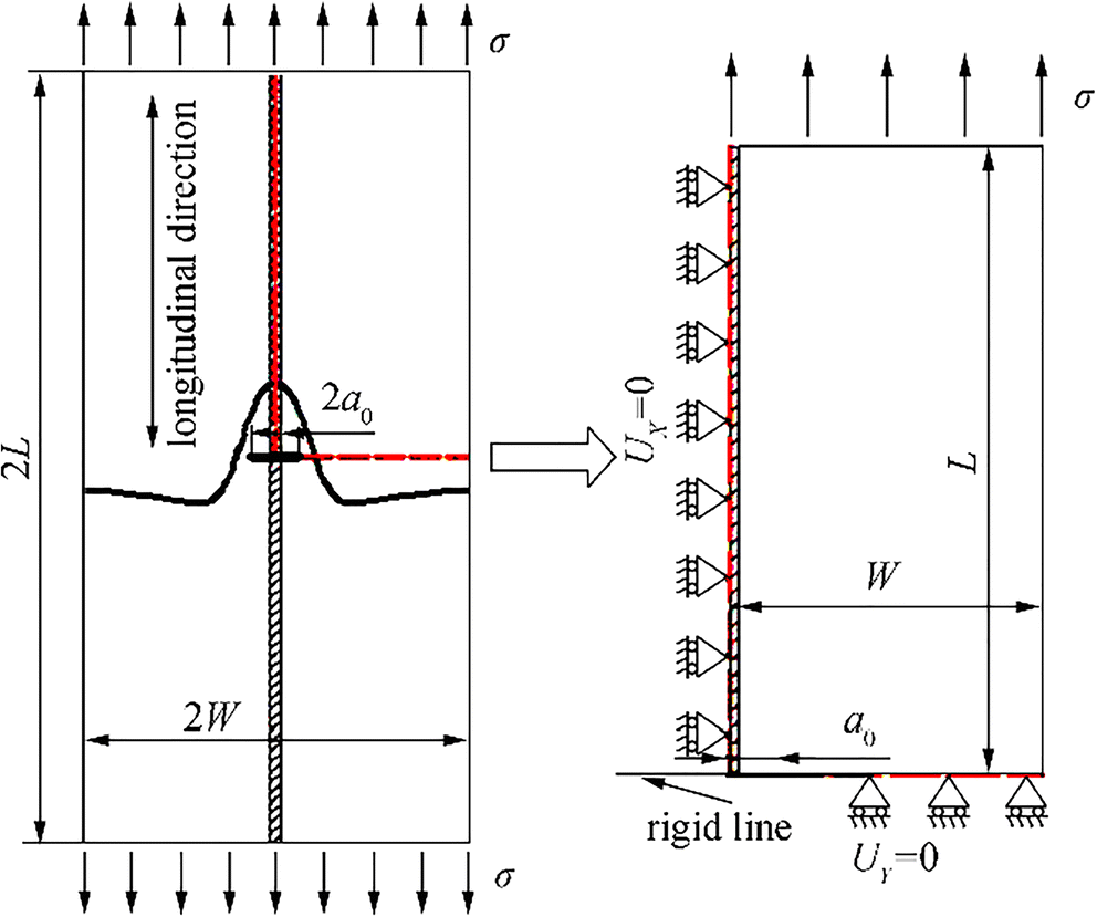 Figure 1 Geometric model
3.2 Finite Element Model
Because the model is welded by two flat plates with symmetry, 1/4 of the model was built in Figure 2 to simplify the analysis. To better simulate crack closure and crack propagation, an analytical rigid line is established at the bottom of the model as a master surface, and the bottom surface of the model is used as a slave surface. Because the plate thickness is much smaller than the length and width of the plate, the model is assumed to be analyzed under plane stress. The boundary condition is taken as follows: a fixed constraint in the x-direction is applied along the y-axis direction. To prevent mutual embedding of materials, an analytical rigid line is defined along the x-axis direction, and a fixed constraint in the y-direction is applied in the region where the crack stops expanding.
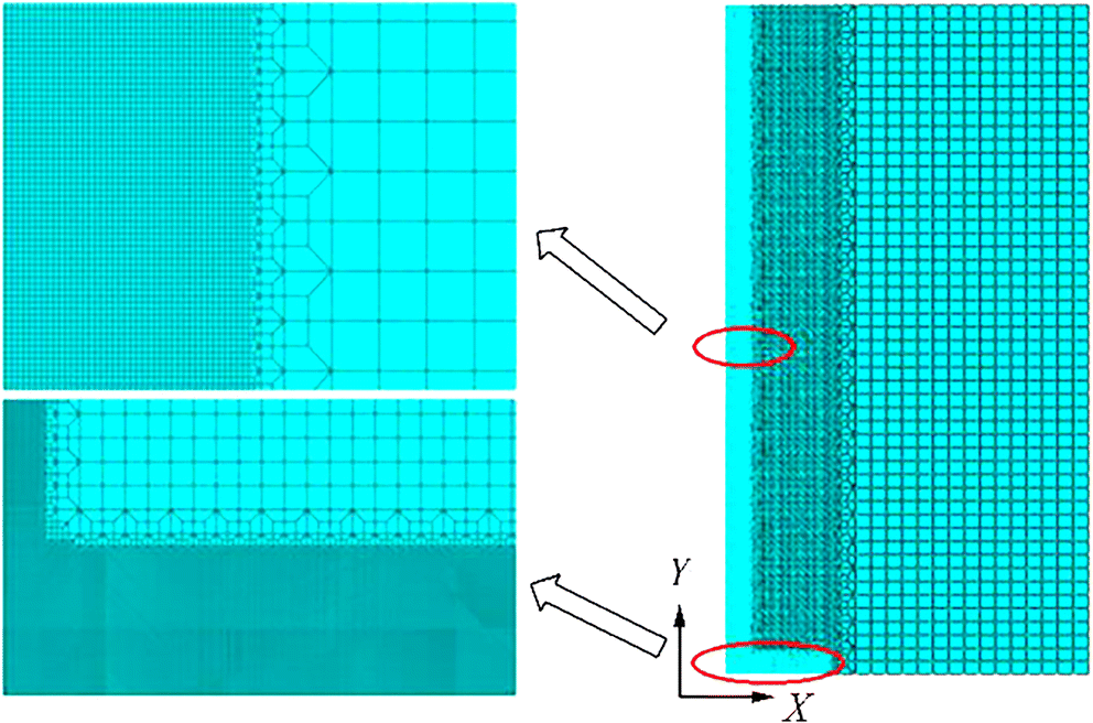 Figure 2 Finite element model
This paper uses node release technology to simulate the process of crack propagation. Due to the influence of calculation time and releasing node time, crack growth is simulated by successive node release at minimum load once every two cycles of loading (Matos and Nowell 2009). Crack opening loads are determined by monitoring the contact state of the first node behind the crack tip (Borrego et al. 2012; Dong et al. 2019). To improve the accuracy of the opening values when the crack actually opens, linear interpolation is used between the remote loads corresponding to the last contact in the first node behind the crack tip and the following load increment (Allison 1988). The model is meshed using the plane stress four-node reduction integral element (CPS4R). The expanded area adopts a refined mesh with a mesh size of 0.05 × 0.05 mm to ensure that the cyclic plastic zone contains at least 3 to 4 elements (Lei 2008; Li and Li 2006).
3.3 Material Properties
The material properties parameters are σy = 345 MPa, E = 206GPa, and v = 0.3. Because plasticity induced crack closure (PICC) is a plastic deformation-based phenomenon, it is very important to accurately simulate the yield and hardening behavior of the materials. The Chaboche combination model can better capture the basic cyclic plastic response of materials such as the Bauschinger effect, plastic shakedown, ratcheting resulting from asymmetric cycles of stress, and mean stress relaxation resulting from an asymmetric strain cycle. Therefore, the Chaboche combinatorial constitutive model is adopted to characterize the nonlinear behavior of the materials, and the model parameters shown in Table 1 are selected from literature (Dong et al. 2016).
Table 1 Chaboche composite model material parametersMaterial E v Q b σs AH32 206GPa 0.3 72 8 345 MPa c1 γ1 c2 γ2 c3 γ3 140 000 8750 75 000 238 1950 0 In Table 1, v is Poisson's ratio, Q is the maximum change of the yield surface, b is the change rate of the yield surface with increasing plastic strain, c1, c2, and c3 are the initial kinematic hardening moduli, and γ1, γ2, and γ3 are the rate of strain increase.
3.4 Introduction of the Welding Residual Stress
The welding residual stress should be self-balanced. However, in the experimental measurement, the measured tensile residual stress is often greater than the compressive residual stress leading to the unbalanced stress field. This stress field will influence the calculation results (Bao et al. 2010). The purpose of this paper is not to simulate the welding residual stress distribution but to better study the redistribution and release of welding residual stress during crack propagation and its effect on crack propagation under constant and variable amplitude loading (Liljedahl et al. 2008). Therefore, this paper adopts the empirical simplification formula of the welding residual stress proposed by Tada and Paris (1983). Due to the mode-I crack propagation, the longitudinal residual stress has a more important role than the transverse residual stress. To simplify the calculation, only the distribution of the longitudinal residual stress is considered:
$$ {\sigma}_y(x)={\sigma}_{0y}\frac{1-{\left(\frac{x}{c_0}\right)}^2}{1+{\left(\frac{x}{c_0}\right)}^4} $$ (4) where σ0y is a parameter defining the maximum value of the tensile residual stress and co is the distance from the y-axis at which the residual stress field changes from positive to negative, i.e., from tensile to compression. Because the stress at the weld is close to or exceeds the material yield stress, σ0y can be taken as 345 MPa, and co has a typical value of 10 mm (George and Ioannis 2009). Considering the calculation efficiency, it is not advisable to choose a larger crack propagation length. Through a large number of finite element calculations, this paper finally chooses to expand only Δa = 5mm (The reasons for selection of co include the following. This paper mainly studies the effect of the ideal residual stress distribution on crack propagation but does not study the specific welding process. In addition, because only the effect of the residual tensile stress is investigated, it is desirable that co is larger than the sum of the crack extension length and initial crack length (c0 > Δa + a0 : 10mm > 5mm + 2mm)). The residual stress distribution is shown in Figure 3.
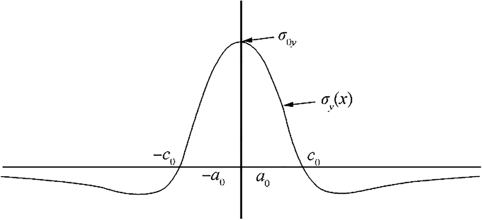 Figure 3 The distribution of welding residual stress
The residual stress file is written in the FORTRAN program and introduced into the calculation model as initial stress by ABAQUS definition user subroutine SIGINI. Since the introduced initial stress cannot fully satisfy the self-balancing condition of the residual stress and boundary conditions, a static analysis is needed to make the residual stress in the test material become the equilibrium stress state. Figure 4 shows the introduced residual stress distribution before and after equilibrium and Eq. 4. The difference between the residual stress distribution of pre-equilibrium, post-equilibrium, and the formula is very small. Therefore, the residual stress distribution after equilibrium is used as the initial residual stress in the calculation model.
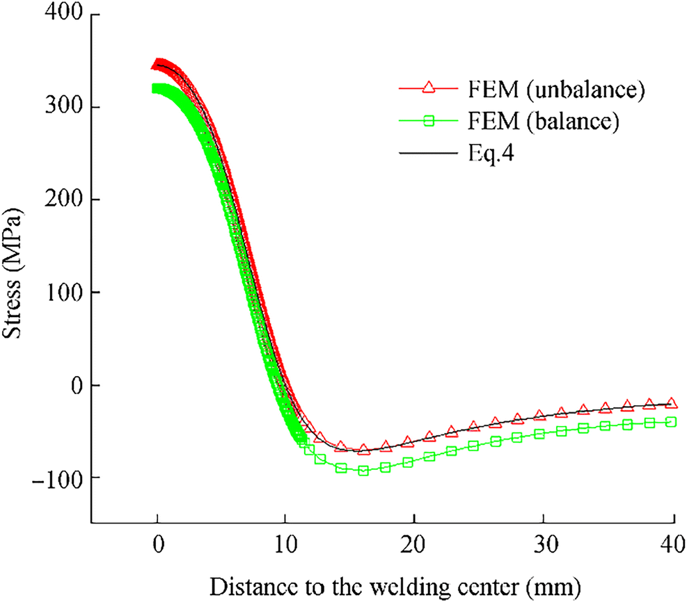 Figure 4 Stress distribution before and after equilibrium
3.5 The Validity of the Finite Element Method
Selected literature (Lv et al. 2016) was used to verify the validity of the finite element method used in this paper. The test model is a four-point bending specimen. First, the finite element model shown in Figure 5 is established by ABAQUS software. This work also uses the node release technique simulating crack growth. The introduced welding residual stress is realized by the ABAQUS definition user subroutine. The crack opening load is determined by the displacement state of the first node behind the crack tip. As shown in Figure 6, the results calculated by finite element analysis in this paper show very good agreement with literature. Therefore, the finite element method used has reliability.
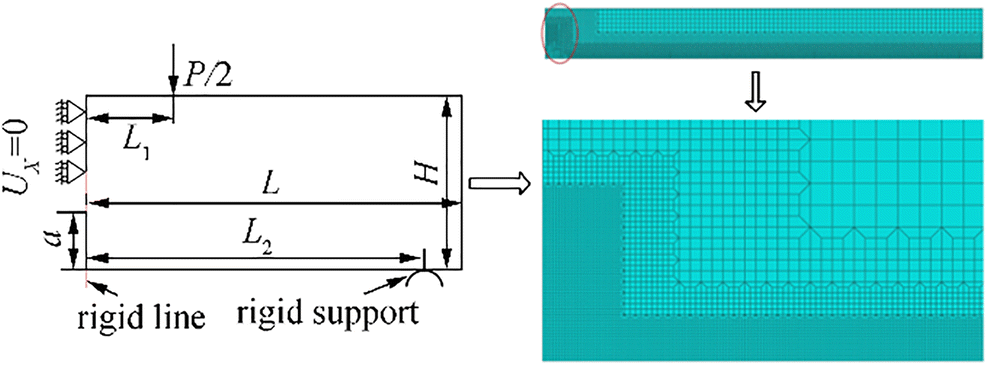 Figure 5 Finite element model and boundary condition (Lv et al., 2016)
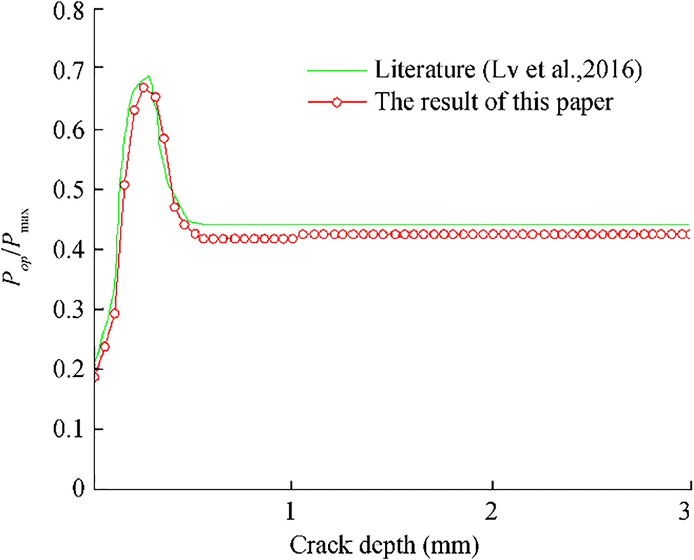 Figure 6 Comparison of the result
4 Study of the Constant Amplitude Loading
4.1 The Effect of the Welding Residual Stress Field
To study the effect of the welding residual stress on crack propagation under constant amplitude loading, the analysis was performed under a stress ratio of R = 0. Figure 7a and b show the curves of crack opening load and crack closure parameter with and without welding residual stress, indicating the welding residual stress has a non-negligible influence on crack propagation.
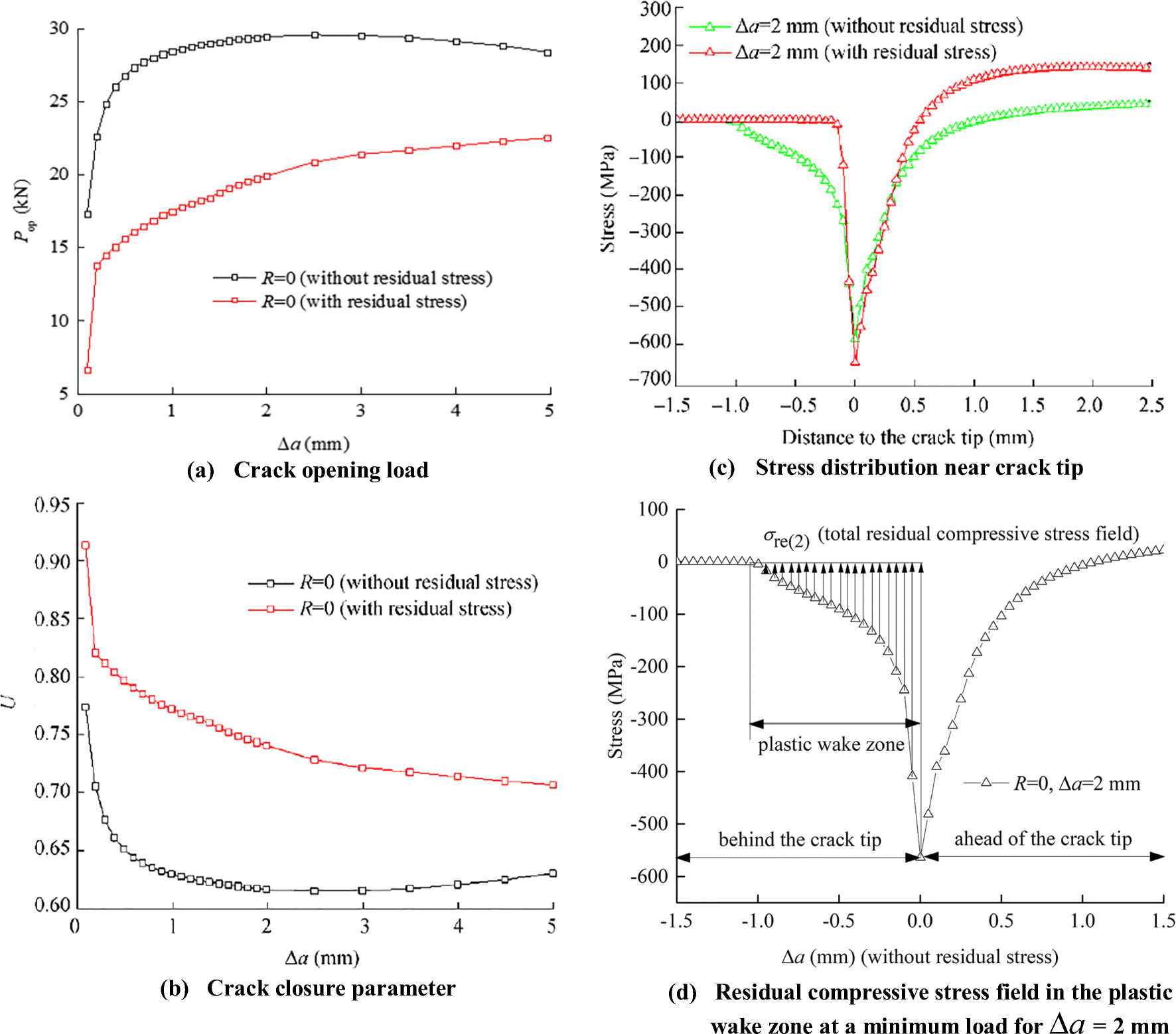 Figure 7 The effect of welding residual stress on Pop, U, and stress distribution
The crack closure weakened in the welding tensile stress region primarily because the residual tensile stress is able to offset some part of the residual compressive stress formed by the external load during unloading. Additionally, the difference between crack closure parameters in the two different cases continuously decreases as the crack length increases, which is probably related to the release of residual stress. This can be considered that the effect on crack propagation is also gradually reducing.
To investigate the evolution of the residual compressive stress field in the plastic wake zone, the paper uses σrre(2), σre(2) to represent the size of the residual compressive stress field with or without welding residual stress for the crack extension length Δa = 2mm (σrre, σre are the sum of all the compressive stress values behind the crack tip at the minimum load with or without welding residual stress, respectively). Figure 7 c and d show the stress distribution near the crack tip for Δa = 2mm. It can be seen that the residual compressive stress field in the plastic wake zone is reduced at the minimum load due to the welding residual tensile stress (|σrre(2)| = 999MPa < |σre(2)| = 2784MPa). Because the residual compressive stress field is the primary factor to affect crack closure, the decreased residual compressive stress will weaken the crack closure to a certain extent, resulting in the increase in crack growth rate. The work also extracts accumulative plastic strain at the crack tip for Δa = 2mm, and the accumulative plastic strain value with welding residual stress is larger than the situation without residual stress (εpre = 0.0373 > εp = 0.021), which indicates that the welding residual tensile stress can increase the plastic deformation at the crack tip. This conclusion agrees with the literature (Li et al. 2011).
4.2 The Effect of the Stress Ratio
The effect of the stress ratio on crack propagation is also significant. The crack propagation in four loading cases with different stress ratios (R = 0, 0.1, 0.2, and 0.3) was studied to investigate the crack closure parameter U and residual stress field distribution.
Based on these results, the crack closure will weaken with an increase in the stress ratio, which is mainly related to the decrease in the residual compressive stress field in the wake zone behind the crack tip. Figure 8c shows that the residual compressive stress field will be reduced with the increase in the stress ratio (|σre(0.1)| = 1974MPa < |σre(0)| = 2993MPa, |σrre(0.1)| = 1023MPa < |σrre(0)| = 1223MPa). The residual compressive stress field formed by the external load and welding residual tensile stress is smaller than with only the external load (|σrre(0.1)| < |σre(0.1)|, |σrre(0)| < |σre(0)|).
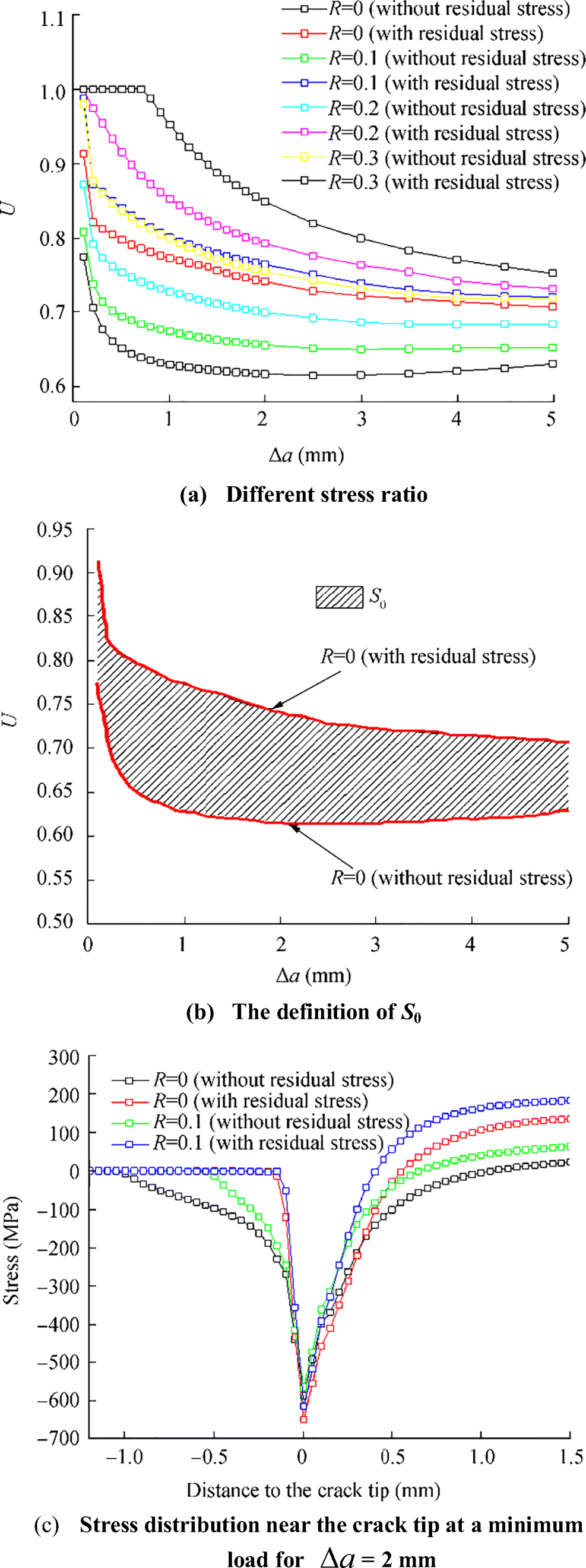 Figure 8 The effect of the stress ratio on crack closure
Quantitative analysis was used to investigate the effect of the stress ratio on the welding residual stress. S0, S0.1, S0.2, and S0.3 are used to represent the area between crack closure parameter curves with or without welding residual stress under different stress ratios (R = 0, 0.1, 0.2, 0.3, respectively), which are the effect of the welding residual stress on crack closure and crack propagation. As shown in Table 2, the effect of the welding residual tensile stress on crack closure gradually reduced with an increase in stress ratio (Uav, Uav(re)), resulting in a decrease in the effect of the welding residual stress on the crack growth rate (S0 > S0.1 > S0.2 > S0.3), which is closely related to the release and redistribution of welding residual stress during crack propagation.
Table 2 Effect of the stress ratioCase Pmax (MPa) R Uav Uav(re) Si 1 320 0 0.638 0.765 0.5591 2 320 0.1 0.677 0.793 0.4912 3 320 0.2 0.725 0.838 0.45 4 320 0.3 0.789 0.902 0.4345 Where Uav(re) and Uav represent the average value of the crack parameter with or without the welding residual stress, respectively, i.e., the level of crack closure. Si describes the effect of stress ratio on crack closure and crack propagation with welding residual stress (i = 0, 0.1 0.2, 0.3, …, …, n) 4.3 The Effect of the Maximum Load
The maximum load also has a non-negligible effect on crack propagation. Cases with maximum load (Pmax = 320, 370, 420 MPa) under R = 0.1 were analyzed. As shown in Figure 9a, the increased maximum load decreases the crack closure without welding residual stress primarily because the load can offset part of the residual stress on the crack faces (|σre(320)| = 1973MPa > |σre(370)| = 1672MPa), as shown in Figure 9b. Alternatively, the law of crack closure is different with welding residual stress. When Δa > 3 mm, the crack closure decreases with an increase in the maximum load. Figure 9c shows the stress field distribution at the minimum load for Δa = 5mm, illustrating the compressive stress field has some reduction (|σre(320)| = 1589MPa > |σre(370)| = 1386MPa). However, the variation law is not obvious for Δa = < 3mm, which is mainly related to the distribution of the welding residual stress. The same quantitative method was performed to investigate the influence of the maximum load for the welding residual stress. As shown in Table 3, overall, the increased maximum load will reduce the influence of the welding residual stress on crack closure (S320 > S370 > S420), indicating that the increased maximum load may promote the release and redistribution of welding residual stress.
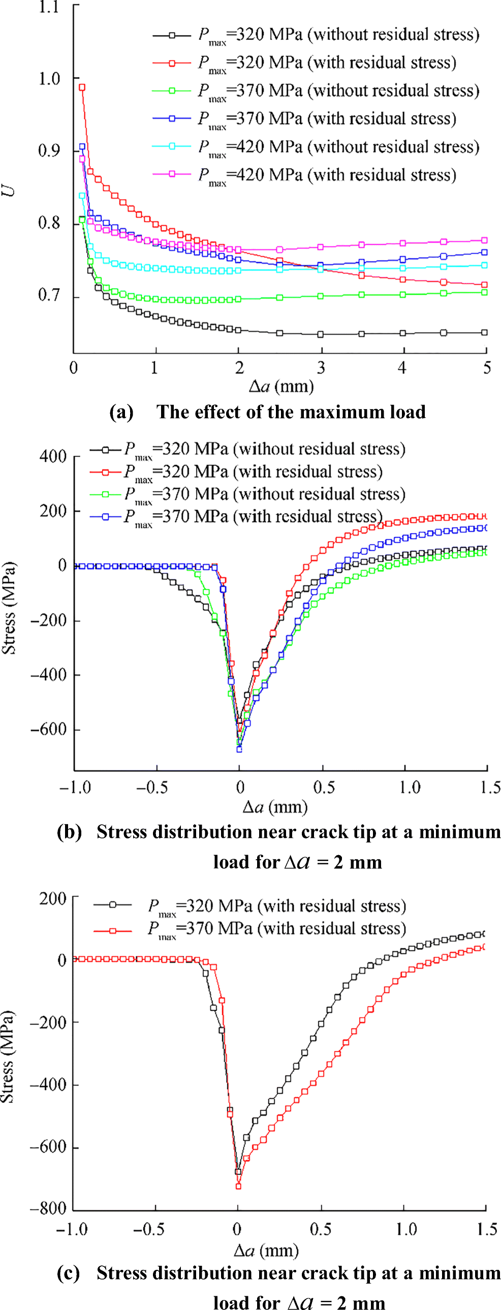 Figure 9 The effect of the maximum load on crack closureTable 3 The effect of the maximum load
Case Pmax (MPa) R Uav Uav(re) Si 1 320 0.1 0.677 0.793 0.4912 2 370 0.1 0.708 0.775 0.2812 3 420 0.1 0.746 0.781 0.1621 4.4 The Analysis of the Effective Stress Intensity Factor Range
The stress intensity factor range is a significant factor affecting crack propagation. The stress intensity factor can be calculated by Feng et al. (2012):
$$ K= Y\sigma \sqrt{\pi a} $$ (5) $$ Y=\left(1-0.1{\left(a/W\right)}^2+0.96{\left(a/W\right)}^4\right)\sqrt{\sec \left(\frac{a}{W}\pi \right)} $$ (6) where W is the width of the model, Y is the correction factor, σ is the applied load, and a is the half crack length.
$$ \Delta {K}_{\mathrm{eff}}=U\Delta K= YU\left({\sigma}_{\mathrm{max}}-{\sigma}_{\mathrm{min}}\right)\sqrt{\pi a} $$ (7) The effective stress intensity factor ranges with or without welding residual stress are obtained by Eq. (7). As shown in Figure 10 a and b, the effective stress intensity factor range with welding residual stress is larger than the case without welding residual stress, indicating the welding residual tensile stress can affect the crack growth rate to some degree. When the stress ratio increases, the effective stress intensity factor range will decrease, indicating a decrease in the crack growth rate. Additionally, the effective stress intensity factor range still increases with an increase in the maximum load. However, the effect caused by the increased maximum load on welding residual stress appears to be a reduction.
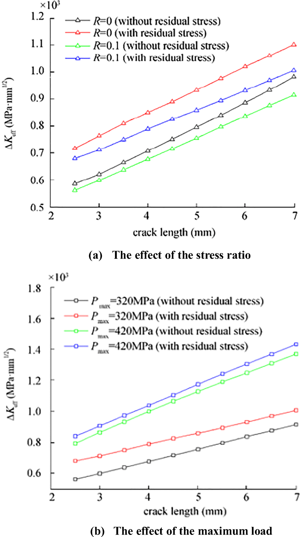 Figure 10 The variety of effective stress intensity factor range under different constant amplitude loads
5 Study of Overloading
5.1 The Effect of the Welding Residual Stress Field
The influence of overload ratio, number of overloads, and other factors were used to study the effect of the welding residual stress on crack propagation under overloading. The main purpose is to consider the effect of overload on the welding residual stress redistribution that result in complex stress changes at the crack tip, thus affecting the crack growth rate. The crack closure parameter and change of residual compressive stress field with or without welding residual stress are investigated for ROL = 1.2 (where ROL = POL/Pmax, POL is the maximum load during the overload) and Δa = 1mm in this section.
As shown in Figure 11a, crack closure appears to decrease first after the overload, then gradually increase, finally recovering to constant amplitude loading. Figure 11b shows that residual compressive stress field in the plastic wake zone will be enhanced after the overload (Δa = 1.3m, |σre(1.2)| = 2345MPa > |σre(1)| = 1667MPa, |σrre(1.2)| = 2024MPa > |σrre(1)| = 931MPa), and the residual compressive stress field after the overload will relatively reduce under the effect of the welding residual tensile stress (|σrre(1.2)| = 2024MPa < |σre(1.2)| = 2345MPa), which is the main reason for the decrease of crack closure and increase of the crack growth rate. In addition, the accumulative plastic strain (Δa = 1mm) will increase at the time of overload (εpre(1.2) = 0.0644 > εpre(1) = 0.0349, εp(1.2) = 0.0394 > εp(1) = 0.0171), and the accumulative plastic strain with welding residual stress is larger (εpre(1.2) > εp(1.2)), indicating that the overload and welding residual tensile stress will increase the plastic deformation at the crack tip.
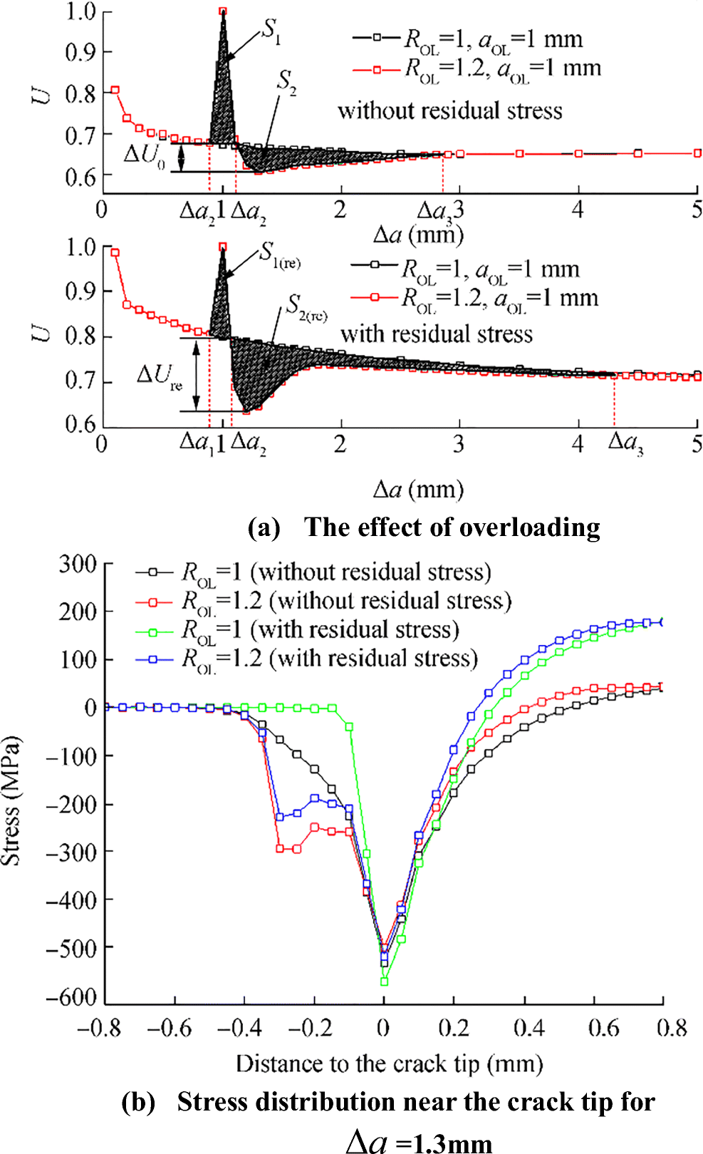 Figure 11 U and stress distribution near the crack tip under overloading
A similar literature method was used to quantify the effect of the welding residual stress on crack propagation under different overloads (Chen et al. 2018). S(re) and S0 are used to represent the influence of the retardation effect during the overload with or without the welding residual stress in Fig. 11a, respectively. The values can be obtained by numerical integration. The increase in S0 and S(re) implies that the retardation effect is enhanced, and it can be expressed as:
$$ \left\{\begin{array}{l}{S}_0=-{S}_1+{S}_2=-{\int}_{\Delta {\alpha}_1}^{\Delta {\alpha}_2}{U}_1\left(\Delta \alpha \right)d\Delta \alpha +{\int}_{\Delta {\alpha}_2}^{\Delta {\alpha}_3}{U}_2\left(\Delta \alpha \right)d\Delta \alpha \\ {}{S}_{(re)}=-{S}_{1(re)}+{S}_{2(re)}=-{\int}_{\Delta {\alpha}_1}^{\Delta {\alpha}_2}{U}_{1(re)}\left(\Delta \alpha \right)d\Delta \alpha +{\int}_{\Delta {\alpha}_2}^{\Delta {\alpha}_3}{U}_{2(re)}\left(\Delta \alpha \right)d\Delta \alpha \end{array}\right. $$ (8) where S1 and S2 represent the acceleration and deceleration effects of crack propagation without welding residual stress, respectively. S1(re) and S2(re) represent the acceleration and deceleration effects of crack propagation with welding residual stress, respectively. Δa1, Δa2, and Δa3 are described in Figure 11a.
As shown in Figure 11a (S(re) = 0.0864 > S0 = 0.0139), the retardation effect with the welding residual tensile stress caused by the overload is larger, which is similar to previous reports (Daneshpour et al. 2012). The residual compressive stress field shown in Table 4 has a large proportion of change from the position of pre-overload to the strongest retardation effect after overload due to the combined effect of residual tensile stress and overload. This leads to the fact that the decreased amplitude of ΔU is larger (the amplitude of ΔU refers to the difference between the minimum value of Umin(overload) after the overload and Uconstant, and the definition of Uconstant is the intersection of the overload curve and constant amplitude loading curve when the overload curve decreased, as shown in Figure 11a; when U recovers to the level of constant amplitude loading, the retardation effect will be also larger.
Table 4 The change in the residual compressive stress fieldσwrs(MPa) a1(mm) σre(1)(MPa) σrre(1)(MPa) × 0.9 − 1549 - √ 0.9 - − 854 a2(mm) σre(2)(MPa) σrre(2)(MPa) Δσ(%) 1.3 − 2345 - 51.39 1.2 - − 1850 116.63 In Table 4, σwrs is the welding residual stress, "×" indicates the case without welding residual stress, "√" indicates the case with welding residual stress, a1 is the position before the overload, a2 is the position of the strongest retardation effect after overload, σre(1), σrre(1) indicate the residual compressive stress field without or with welding residual for the Δa = a1, and σre(2), σrre(2) indicate the residual compressive stress field without or with welding residual for Δa = a2.
5.2 The Effect of the Overload Ratio
To investigate the effect of the overload ratio on welding residual stress, the analysis is carried out for four cases with different overload ratios (ROL = 1.2, 1.3, 1.5, and 1.7). The relationship between the crack closure parameter and crack propagation length with or without welding residual stress under different overload ratios is shown in Figure 12 a and b. Based on the quantitative result of the retardation effect shown in Table 5, the retardation effect is gradually enhanced with the increase in overload ratio in two different cases, and the retardation effect with welding residual stress is larger (S(re) > S0, ΔUre > ΔU0). In addition, with the increase in the overload ratio, the value of U is more difficult to recover to the level of constant amplitude loading after overloading. The difference between the overloading and constant amplitude loading gradually increases indicating the increased overload ratio may somewhat reduce the effect of welding residual stress.
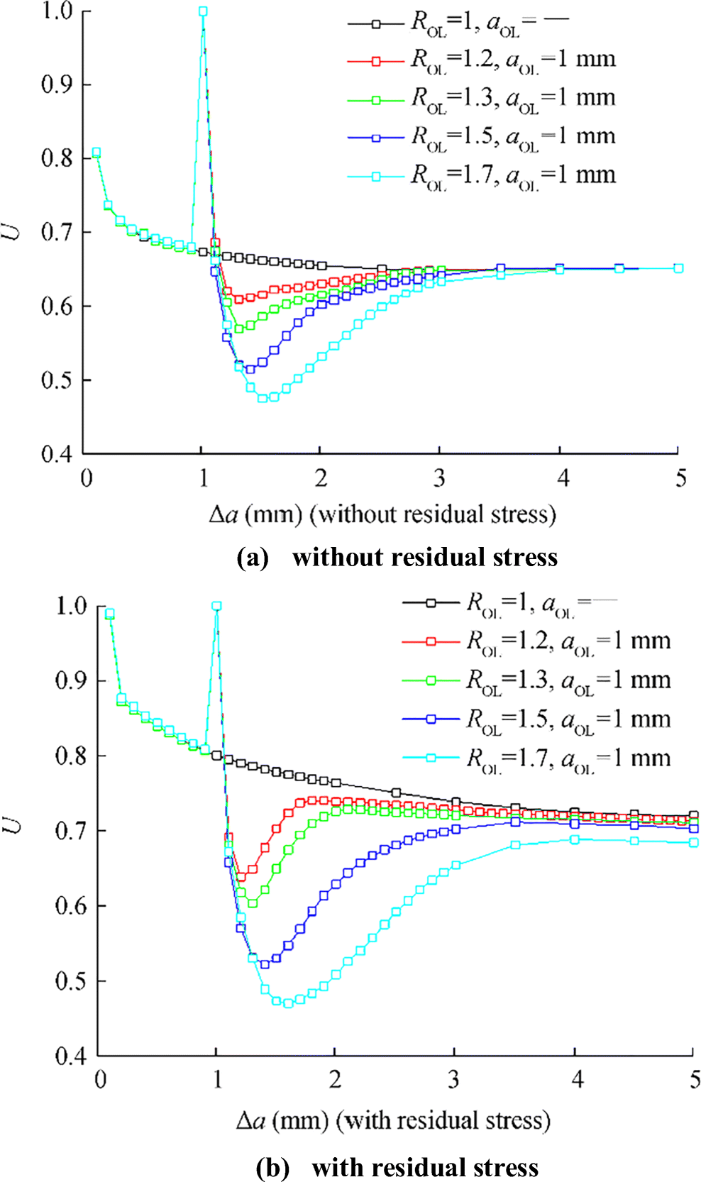 Figure 12 The effect of the overload ratio on crack closureTable 5 The effect of the retardation effect
ROL aOL(mm) ΔU0 ΔUre S0 S(re) 1.2 1 0.0612 0.1616 0.0109 0.0864 1.3 1 0.1004 0.1957 0.0309 0.137 1.5 1 0.1546 0.2771 0.0916 0.2878 1.7 1 0.1946 0.3287 0.1668 0.4823 5.3 The Effect of the Overload Ratio
To investigate the effect of number of overloads on welding residual stress, the analysis is performed for four cases with different number of overloads (N = 1, 3, 7, and 11). Based on the quantitative result of the retardation effect shown in Table 6, the retardation effect is gradually enhanced with an increase in the number of overloads, and the retardation effect with the welding residual stress is larger (S(re) > S0, ΔUre > ΔU0) than the case without welding residual stress (Figure 13). Although the retardation effect increases with the increased number of overloads, the trend of the crack closure parameters is relatively close in the late stage, which indirectly indicates that the increased number of overloads do not have an obvious effect on the release of welding residual stress.
Table 6 The effect of the retardation effectROL N aOL(mm) ΔU0 ΔUre S0 S(re) 1.2 1 1 0.0612 0.1616 0.0109 0.0869 1.2 3 1 0.1032 0.2004 0.0364 0.1113 1.2 7 1 0.1432 0.2314 0.0612 0.1290 1.2 11 1 0.172 0.2874 0.0939 0.1676 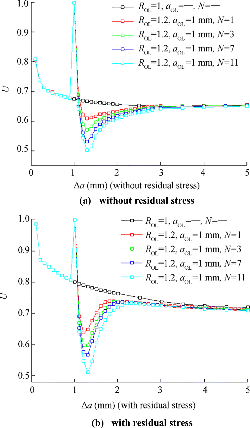 Figure 13 The effect of the number of overloads on crack closure
5.4 The Analysis of the Effective Stress Intensity Factor Range
To express the law of crack propagation during overload, the effective stress intensity factor range is obtained by Eq. (7). As shown in Figure 14, the crack parameter U suddenly increases and then gradually decreases, finally returning to the level of constant amplitude loading. When the overload ratio and number of overloads increase, the retardation effect is relatively enhanced resulting in the reduction in the crack growth rate. The retardation effect is relatively stronger with the welding residual stress. The increased overload ratio may also reduce the effect of welding residual stress to a certain extent. In contrast, the effect of the number of overloads is not very obvious.
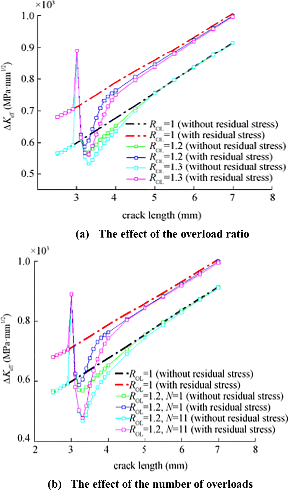 Figure 14 The variety of effective stress intensity factor range under different overloads
6 Conclusions
Welding residual stress has a non-negligible influence on crack propagation. Based on the crack closure method, the effect of the welding residual stress on crack propagation was investigated under constant amplitude loading and overloading, and the influencing factors of stress ratio, maximum load, overload ratio, and number of overloads discussed. The factors were quantitatively analyzed to understand the effect of the welding residual stress on the crack propagation law. The following conclusions were drawn:
1) Welding residual tensile stress can offset part of the residual compressive stress caused by the external loading, reducing the total residual compressive stress field in the plastic wake zone, which can reduce the crack closure thereby increasing the crack growth rate.
2) The effect of the welding residual tensile stress on the crack closure continuously decreased with the increase in the stress ratio under constant amplitude loading. The ability of the welding residual tensile stress to offset the residual compressive stress in the wake zone tends to decrease, which is related to the release and redistribution of the welding residual stress during crack propagation.
3) The effect of the maximum load is somewhat different with or without welding residual stress. Under no welding residual stress, the crack closure decreased with an increase in the maximum load. Alternatively, the variable law of the crack closure is not very obvious. Only when the crack length extends to a certain extent, the crack closure will decrease with the increase in the maximum load.
4) Under the combined effect of the overload and welding residual tensile stress, the retardation effect will increase to some degree primarily because the residual compressive stress field has a significant increase resulting in a large decrease of the crack closure parameter. When U recovers to the level of constant amplitude loading, the retardation effect also gradually increased.
5) The retardation effect caused by overload is enhanced with the increase in the overload ratio and number of overloads, and the effect with the welding residual tensile is particularly obvious. When the overload ratio increases, it will promote the release of the welding residual stress and reduce its influence on the crack propagation to a certain extent. In contrast, the effect of the number of overloads is not very obvious.
6) The effective stress intensity factor range can reflect the crack growth rate well. In the case of welding residual tensile stress, the crack growth rate is relatively large. A decreased maximum load or increased stress ratio will reduce the effective stress intensity factor range, resulting in a reduction in the crack growth rate. For the case of the overload, the retardation effect is relatively enhanced with the increase in the overload ratio and number of overloads. The retardation effect caused by the overload under welding residual stress is greater.
-
Figure 1 Geometric model
Figure 2 Finite element model
Figure 3 The distribution of welding residual stress
Figure 4 Stress distribution before and after equilibrium
Figure 5 Finite element model and boundary condition (Lv et al., 2016)
Figure 6 Comparison of the result
Figure 7 The effect of welding residual stress on Pop, U, and stress distribution
Figure 8 The effect of the stress ratio on crack closure
Figure 9 The effect of the maximum load on crack closure
Figure 10 The variety of effective stress intensity factor range under different constant amplitude loads
Figure 11 U and stress distribution near the crack tip under overloading
Figure 12 The effect of the overload ratio on crack closure
Figure 13 The effect of the number of overloads on crack closure
Figure 14 The variety of effective stress intensity factor range under different overloads
Table 1 Chaboche composite model material parameters
Material E v Q b σs AH32 206GPa 0.3 72 8 345 MPa c1 γ1 c2 γ2 c3 γ3 140 000 8750 75 000 238 1950 0 Table 2 Effect of the stress ratio
Case Pmax (MPa) R Uav Uav(re) Si 1 320 0 0.638 0.765 0.5591 2 320 0.1 0.677 0.793 0.4912 3 320 0.2 0.725 0.838 0.45 4 320 0.3 0.789 0.902 0.4345 Where Uav(re) and Uav represent the average value of the crack parameter with or without the welding residual stress, respectively, i.e., the level of crack closure. Si describes the effect of stress ratio on crack closure and crack propagation with welding residual stress (i = 0, 0.1 0.2, 0.3, …, …, n) Table 3 The effect of the maximum load
Case Pmax (MPa) R Uav Uav(re) Si 1 320 0.1 0.677 0.793 0.4912 2 370 0.1 0.708 0.775 0.2812 3 420 0.1 0.746 0.781 0.1621 Table 4 The change in the residual compressive stress field
σwrs(MPa) a1(mm) σre(1)(MPa) σrre(1)(MPa) × 0.9 − 1549 - √ 0.9 - − 854 a2(mm) σre(2)(MPa) σrre(2)(MPa) Δσ(%) 1.3 − 2345 - 51.39 1.2 - − 1850 116.63 Table 5 The effect of the retardation effect
ROL aOL(mm) ΔU0 ΔUre S0 S(re) 1.2 1 0.0612 0.1616 0.0109 0.0864 1.3 1 0.1004 0.1957 0.0309 0.137 1.5 1 0.1546 0.2771 0.0916 0.2878 1.7 1 0.1946 0.3287 0.1668 0.4823 Table 6 The effect of the retardation effect
ROL N aOL(mm) ΔU0 ΔUre S0 S(re) 1.2 1 1 0.0612 0.1616 0.0109 0.0869 1.2 3 1 0.1032 0.2004 0.0364 0.1113 1.2 7 1 0.1432 0.2314 0.0612 0.1290 1.2 11 1 0.172 0.2874 0.0939 0.1676 -
Allison JE (1988) The measurement of crack closure during fatigue crack growth. In: Fracture Mechanics: Eighteenth Symposium, ASTM STP 945, vol 18, pp 913–933 Antunes FV, Rodrigues DM (2008) Numerical simulation of plasticity induced crack closure: identification and discussion of parameters. Eng Fract Mech 75(10): 3101–3120. https://doi.org/10.1016/j.engfracmech.2007.12.009 Antunes FV, Borrego LF, Costa JD et al (2010) A numerical study of fatigue crack closure induced by plasticity. Fatigue Fract Eng Mater Struct 27(9): 825–835. https://doi.org/10.1111/j.1460-2695.2004.00738.x Antunes FV, Sousa T, Branco R et al (2015) Effect of crack closure on non-linear crack tip parameters. Int J Fatigue 53: 63. https://doi.org/10.1016/j.ijfatigue.2014.10.001 Bao R, Zhang X (2010) An inverse method for evaluating weld residual stresses via fatigue crack growth test data. Eng Fract Mech 77(16): 3143–3156. https://doi.org/10.1016/j.engfracmech.2010.08.010 Bao R, Zhang X, Yahaya NA et al (2010) Evaluating stress intensity factors due to weld residual stresses by the weight function and finite element methods. Eng Fract Mech 77(13): 2550–2566. https://doi.org/10.1016/j.engfracmech.2010.06.002 Borrego LP, Antunes FV, Costa JD, Ferreira JM (2012) Numerical simulation of plasticity induced crack closure under overloads and high–low blocks. Eng Fract Mech 95: 57–71. https://doi.org/10.1016/j.engfracmech.2012.07.016 Chen J, You M, Huang Y (2018) Quantitative analysis on the influence of tensile overloading on crack opening stress. J Harbin Eng Univ 39(1): 10–15. https://doi.org/10.11990/jheu.201608015 Cochran KB, Dodds RH, Hjelmstad KD et al (2011) The role of strain ratcheting and mesh refinement in finite element analyses of plasticity induced crack closure. Int J Fatigue 33(9): 1205–1220. https://doi.org/10.1016/j.ijfatigue.2011.03.005 Daneshpour S, Dyck J, Ventzke V, Huber N (2012) Crack retardation mechanism due to overload in base material and laser welds of Al alloys. Int J Fatigue 42: 95–103. https://doi.org/10.1016/j.ijfatigue.2011.07.010 Ding ZY, Wang XG, Gao ZL (2013) Numerical simulation of the effect of loading history and crack closure on crack propagation behavior. Eng Mechanic 30(8): 244–250. https://doi.org/10.6052/j.issn.1000-4750.2012.04.0272 Dong Q, Yang P, Xu G, Deng J (2016) Mechanisms and modeling of low cycle fatigue crack propagation in a pressure vessel steel Q345. Int J Fatigue 2016: 2–10. https://doi.org/10.1016/j.ijfatigue.2016.03.026 Dong Q, Yang P, Xu G (2019) Low cycle fatigue analysis of CTOD under variable amplitude loading for AH-32 steel. Mar Struct 63: 257–268. https://doi.org/10.1016/j.marstruc.2018.10.002 Elber W (1971) The significance of fatigue crack closure. Damage Tolerance in Aircraft Structures, ASTM STP, vol 486, pp 230–242 Feng GQ, Garbatov Y, Soares CG (2012) Probabilistic model of the growth of correlated cracks in a stiffened panel. Eng Fract Mech 84: 83–95. https://doi.org/10.1016/j.engfracmech.2012.01.008 George L, Ioannis D (2009) Numerical investigation of through crack behavior under welding residual stresses. Eng Fract Mech 76(11): 1691–1702. https://doi.org/10.1016/j.engfracmech.2009.03.006 Han Y, Cui WC, Huang XP, et al (2007) Fatigue strength assessment of large-scale ship structures. Ship Building of China Huang XP, Moan T (2007) Improved modeling of the effect of R-ratio on crack growth rate. Int J Fatigue 29: 591–602. https://doi.org/10.1016/j.ijfatigue.2006.07.014 Kim JS, Kim CY, Song JH (1991) Fatigue crack growth and closure through a tensile residual stress field under random loading. Key Eng Mater 51-52: 283–288. https://doi.org/10.4028/www.scientific.net/KEM.51-52.283 Larue JE, Daniewicz SR (2007) Predicting the effect of residual stress on fatigue crack growth. Int J Fatigue 29(3): 508–515. https://doi.org/10.1016/j.ijfatigue.2006.05.008 Lee C, Chang K (2011) Finite element computation of fatigue growth rates for mode I cracks subjected to welding residual stresses. Eng Fract Mech 78(13): 2505–2520. https://doi.org/10.1016/j.engfracmech.2011.06.006 Lei Y (2008) Finite element crack closure analysis of a compact tension specimen. Int J Fatigue 30(1): 21–31. https://doi.org/10.1016/j.ijfatigue.2007.02.012 Li YZ, Li XF (2006) A study of the numerical simulation technique for fatigue crack closure. Mechanic Sci Technol 25(10): 1233–1237. https://doi.org/10.1016/S1003-6326(06)60040-X Li LB, Moan T, Zhang B (2007) Residual stress shakedown in typical weld joints and its effect on fatigue of FPSOs. Proceedings of the 26th International Conference on Offshore Mechanics and Arctic Engineering Li YZ, Wang Q, Zhang ZP, He J (2011) Exploring further fatigue crack closure in residual stress field through numerical simulation. J Northwestern Polytech Univ 29(1): 97–102. https://doi.org/10.3969/j.issn.1000-2758.2011.01.018 Li YZ, Geng WJ, Shu YX, WANG Q (2014) Fatigue crack closure and residual stress effect of overload. J Northwestern Polytech Univ 30(4): 529–535. https://doi.org/10.3969/j.issn.1000-2758.2014.04.010 Liljedahl CD, Tan ML, Zanellato O et al (2008) Evolution of residual stresses with fatigue loading and subsequent crack growth in a welded aluminium alloy middle tension specimen. Eng Fract Mech 75(13): 3881–3894. https://doi.org/10.1016/j.engfracmech.2008.02.005 Liljedahl CD, Brouard J, Zanellato O et al (2009) Weld residual stress effects on fatigue crack growth behaviour of aluminium alloy 2024-T351. Int J Fatigue 31(6): 1081–1088. https://doi.org/10.1016/j.ijfatigue.2008.05.008 Lv HT, Wang JM, Liu XR (2016) Numerical simulation for residual stress field of shot-peening on crack closure effect. 29(2): 102–110. https://doi.org/10.11933/j.issn.1007-9289.2016.02.015 Matos PFPD, Nowell D (2008) Numerical simulation of plasticity-induced fatigue crack closure with emphasis on the crack growth scheme: 2D and 3D analyses. Eng Fract Mech 75(8): 2087–2114. https://doi.org/10.1016/j.engfracmech.2007.10.017 Matos PFPD, Nowell D (2009) Experimental and numerical investigation of thickness effects in plasticity-induced fatigue crack closure. Int J Fatigue 31(11–12): 1795–1804. https://doi.org/10.1016/j.ijfatigue.2008.12.003 Tada H, Paris PC (1983) The stress intensity factor for a crack perpendicular to the welding bead. Int J Fract 21(4): 279–284. https://doi.org/10.1007/BF00942346 Tan JM, Fitzpatrick ME, Edwards L et al (2007) Stress intensity factors for through-thickness cracks in a wide plate: derivation and application to arbitrary weld residual stress fields. Eng Fract Mech 74(13): 2030–2054. https://doi.org/10.1016/j.engfracmech.2006.10.017 Terada H (2011) Stress intensity factor analysis and fatigue behavior of a crack in the residual stress field of welding. Fatigue Aircraft Struct 2011(3): 5–15. https://doi.org/10.2478/v10164-010-0032-8 Wang H, Buchholz FG, Richard HA, Jägg S, Scholtes B (1999) Numerical and experimental analysis of residual stresses for fatigue crack growth. Comput Mater Sci 16(1–4): 104–112. https://doi.org/10.1016/s0927-0256(99)00052-x Wang F, Huang XP, Cui WC (2014) Fatigue life prediction of cracked stiffened plate using the improved fatigue crack growth rate model. J Ship Mechan 18(6): 700–710. https://doi.org/10.3969/j.issn.1007-7294.2014.06.009 Wang JM, Zhao LL, Lv HT (2016). Effect shot peening residual stress on crack growth fatigue life. 37(4): 608-613. https://doi.org/10.11990/jheu.201412022