Analysis of the Impact of Thermochemical Recuperation of Waste Heat on the Energy Efficiency of Gas Carriers
https://doi.org/10.1007/s11804-020-00127-5
-
Abstract
Enlarging the fleet of gas carriers would make it possible to respond to the growing demand for hydrocarbon gases, but it will increase carbon dioxide emissions. The International Maritime Organization (IMO) has developed the energy efficiency design index (EEDI) with the objective of carbon emission reduction for new ships. In this paper, thirty gas carriers transporting liquefied natural gas (LNG) and liquefied petroleum gas (LPG) and equipped with various types of main engines are considered. As shown by the calculation of the attained EEDI, 2 of the 13 LPG carriers and 6 of the 17 LNG carriers under study do not comply with the EEDI requirements. To meet the stringent EEDI requirements, applying thermochemical regenerators (TCRs) fed by main engine exhaust gases is suggested. Mathematical modeling is applied to analyze the characteristics of the combined gas-turbine-electric and diesel-electric power plant with thermochemical recuperation of the exhaust gas heat. Utilizing TCR on gas carriers with engines fueled by syngas produced from boil-off gas (BOG) reduces the carbon content by 35% and provides the energy efficiency required by IMO without the use of other technologies.Article Highlights• EEDI calculation for LNG carriers has distinctive features, depending on ice class, type of propulsion systems, and the boil-off gas treatment method.• Operating LNG carriers on boil-off gas cannot always ensure the com-pliance of the carriers with the EEDI requirements of the most stringent Phase 3.• Utilizing TCR on gas carriers fueled by syngas produced from BOG will provide the energy efficiency required by IMO without the use of other energy-efficient technologies. -
1 Introduction
Human demand for energy will continue to grow to satisfy various needs. According to the International Energy Outlook data (US Energy Information Administration 2017), global energy consumption will grow by 28% between 2015 and 2040. In addition, energy demand is predicted to increase by about one third in the next 25 years (BP 2018).
The main source of energy nowadays is hydrocarbon organic fuel, the extraction of which is getting more complicated at higher energy expenditure. However, the most exploitable oil and gas fields were almost depleted in the late twentieth century. Thus, oil and gas extraction is steadily shifting toward offshore reserves.
Developed countries have placed significant emphasis on alternative energy based on renewable energy sources. However, despite the vigorous introduction of the technologies using these energy sources, the share of natural gas as a hydrocarbon organic fuel will continue to grow. Gas consumption in the world energy balance will increase from 23% in 2016 to 26% in 2040 (Outlook for Energy 2018).
The following technologies can be implemented to transport natural gas (Karabetsou and Tzannatos 2003):
1) Pipeline transportation
2) Liquefied natural gas (LNG) transportation
3) Compressed natural gas (CNG) transportation
4) Gas-to-liquids transportation
Considering the current situation in the world gas market (production and transportation flows), the geography of exporters and importers, and the level of gas transportation technologies development, it can be argued that pipeline and LNG transportation are preferred technologies. This is supported by the opinions of the energy market experts. For instance, Westwood Global Energy Group expects global LNG capital expenditure (Capex) to total $236 billion over the 2018-2022 period based on its latest analysis of sanctioned and upcoming projects.
According to UNCTAD, more than 90% of the world's cargo is transported by sea, as it results in lower energy expenditure compared with that associated with other means of transport.
By 2035, almost half of the extracted natural gas is expected to be transported by sea as LNG. The geography of these voyages is quite broad. According to the IGU (2018), the distance covered by the shortest LNG voyage in 2017 was 240 nm (from Algeria to Spain), and the longest one was 15 605 nm (from the US to China). The average LNG voyage route is 8415 nm long.
Expanding the fleet of gas carriers would make it possible to respond to the world's growing demand for hydrocarbon gases, but it will result in an increase of environmental pressures on the atmosphere, in particular, additional emission of greenhouse gases. A distinguishing feature of these types of ships is the potential emission of boil-off gas (BOG) along with carbon dioxide pollution, leading to an increase in methane slip. Although the International Maritime Organization (IMO) has not yet imposed restrictions on methane emission, its level from international shipping is subject to monitoring (IMO 2015).
In this paper, the features of gas carriers and their transported cargoes are discussed. The main component of LNG is methane (89%-98%), complemented by ethane (1.4%-9.5%), propane (0.4%-2.5%), butane (0.1%-0.5%), and nitrogen (0.1%-0.5%). LNG is carried at atmospheric pressure and temperatures lower than the boiling temperature of methane (− 161.5°С). This allows decreasing cargo volume by approximately 600 times.
There are two types of LNG carriers on their containment systems (MAN Diesel and Turbo 2013):
1) Those with self-supporting tanks, which are rigid structures with external heat insulation, such as spherical (Moss) or prismatic (SPB) tanks
2) Those with membrane tanks, whereby the membranes are heat-insulated and are fully integrated into the hull and rely on hull's strength
The latter are the most prevalent today, comprising 74% of the world's fleet of gas carriers (IGU 2018). The largest ships are 31 Q-flex gas carriers (210000-217 000 m3 of cargo capacity) and 14 Q-max carriers (261700-266 000 m3), built over 2007 to 2010. The average cubic capacity for gas carriers ordered in 2017 was 173 300 m3.
During transportation, a part of the cargo evaporates because of heat exchange between the surfaces of the cargo transportation system and the environment. The boil-off rate (BOR) is accepted as an indicator to estimate the BOG volume. The BOR is defined as the percentage ratio of the daily BOG generation (VBOG) to the total amount of liquefied cargo (VLNG).
According to Głomski and Michalski (2011), the BOR for the modern gas carriers ranges between 0.1% and 0.15% in laden conditions and 0.06% and 0.1% in ballast, depending on ship design and generation.
In the second half of the twentieth century, the first specialized gas carrier Methane Princess was equipped with a steam turbine propulsion system of 10.2 MW capacity. Steam turbine propulsion systems were widely used on gas carriers. By 2014, 274 gas carriers had been equipped with main steam turbine machines, but they were almost completely replaced by diesel power plants in subsequent orders. In mid-2007, gas carriers with steam turbine propulsion systems were about 40% of the total number of orders, but as of July 1, 2014, they comprised only 8%.
There is now a great diversity of conventional and advanced types of propulsion for gas carriers (Fernández et al. 2017).
Depending on the number of fuels in use, propulsion systems can be single-fueled (SF), dual-fueled (DF), or tri-fueled (TF).
Different types of turbine plants could be used for propulsion, such as the conventional steam turbine (ST), ultrahigh-pressure steam turbine (UST), and gas-turbine (GT) propulsion systems. Two-stroke low-speed (D2S) and four-stroke medium-speed (D4S) diesel engines can also be used as the main engines for gas carriers.
Engine to propeller power transmission can be both mechanical and electrical.
In addition, there could be a combination of different types of main engines, such as the combined gas turbine and steam system, as well as combined transmissions. For example, the ST and gas engines, developed by Mitsubishi Heavy Industries, Ltd. is a combined propulsion system that includes an UST on the port side and an electric propulsion plant powered by dual-fuel diesel engines on the starboard side (Hiramatsu et al. 2016).
There are two main types of ship power plants for gas carriers:
1) Those with a re-liquefaction system
2) Those with compressors, which are used for supplying pressured gas derived from the BOG to the installed engines
In the former case, a re-liquefaction unit is an integral part of ship equipment. In the latter case, a gas-from-BOG system is necessary. This system can contain high-pressure or low-pressure compressors, depending on the main engine design.
Hence, a DF D4S E LP plant is an electric propulsion system powered by dual-fuel medium-speed diesel engines with a low-pressure gas compression system.
An analysis of propulsion plants for the current fleet of LNG carriers at the end of 2016 demonstrated that there were 52% of conventional ST plants, 26% of TF D4S E LP plants, 10% of SF D2S M R plants, 5% of DF D4S E LP plants, 4% of DF D2S M HP plants, and 3% of DF UST M LP plants.
The features of gas carriers described above are considered when calculating the energy efficiency design index (EEDI) for new ships.
In general, the gas carriers under consideration have the following features with regard to their impact on the atmosphere:
1) Cargo partly evaporates during shipping, and BOG relief into the atmosphere pollutes the atmosphere with volatile hydrocarbons.
2) BOG re-liquefaction requires substantial additional energy consumption reaching 3-6 MW (Gomez et al. 2014), which has a negative impact on the EEDI.
3) Cargo can be used as fuel for the installed main and/or auxiliary engines, and the levels of carbon dioxide emission from natural gas and petroleum gas combustions are lower than that from fuel oil.
4) BOG could be used in thermochemical regenerators (TCRs) for the generation of syngas, which can be fed to engines, thus affecting the final EEDI value.
5) Syngas can be generated without additional energy consumption through waste heat recovery of exhaust gases.
The novelty of this article is the idea to apply TCR fed by main engine exhaust gases to improve the energy efficiency of gas carriers, whose propulsion engines are fueled by the BOG cargo, which in addition to natural gas consisting largely of methane, also contains heavier alkanes such as ethane, propane, and butane.
The paper is organized as follows: In Section 2, the impact of gas carriers on CO2 emission is analyzed. In Section 3, the procedure of EEDI estimation for gas carriers is analyzed. Section 4 presents the results of energy efficiency calculations for modern gas carriers with various power plants, and Section 5 describes the impact of TCR included in ship power plants on the final EEDI value.
2 Analysis of Gas Carriers' Influence on the Carbon Dioxide Emission Level
The data published in SIGTTO (2014) indicate that liquefaction plants and receiving terminals have been built on every continent but Antarctica (Table 1).
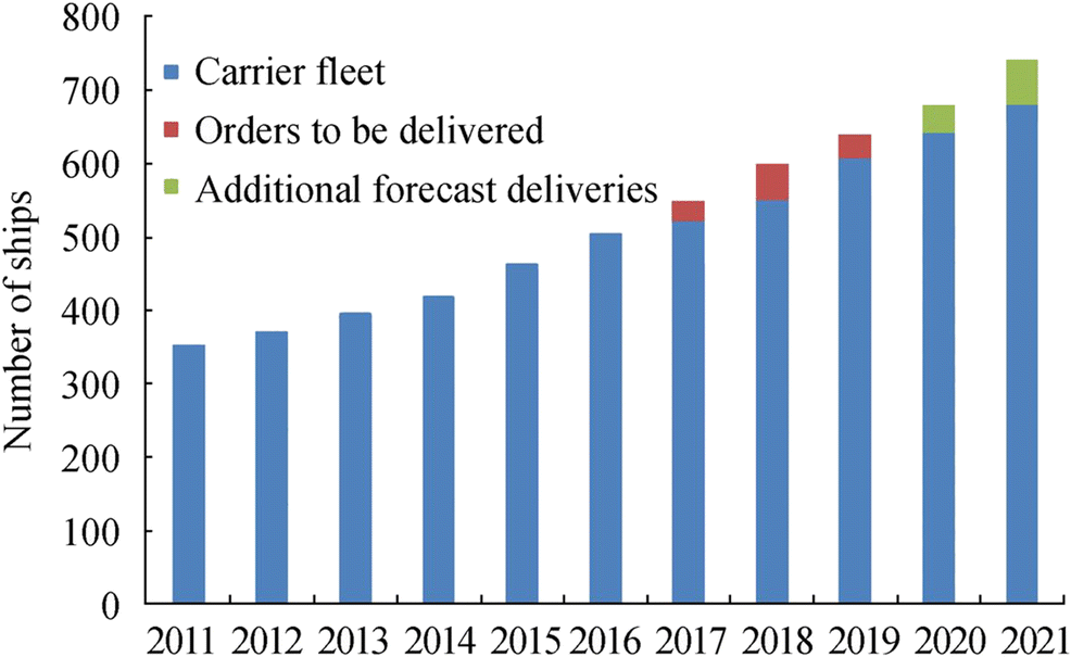
Table 1 LNG industry growth over the past 20 yearsParameters 1993 2003 2013 Liquefaction plants 11 15 26 Receiving terminals 31 46 104 LNG carriers 76 152 393 Number of importing countries 9 13 29 LNG imports (million tons) 61.0 125.2 236.9 The share of LNG carriers continues to grow and is currently 3% of the world fleet, both by the number of ships and by deadweight. The positive forecast (Adeosun 2017) for a quantitative and a qualitative growth of LNG carriers is supported by the construction of large receiving terminals in European ports, development of innovative gas production technologies, exploration of new gas fields, and, especially, the growing potential of LNG export terminals in Australia and the USA (Figure 1).
According to Lloyd's List Intelligence, 472 gas carriers were in service as of January 2018, with total deadweight exceeding 39.2 million tons. Westwood Global Energy Group also expects 265 more ships of this type to be delivered over 2018-2022 (Westwood Global Energy Group 2018).
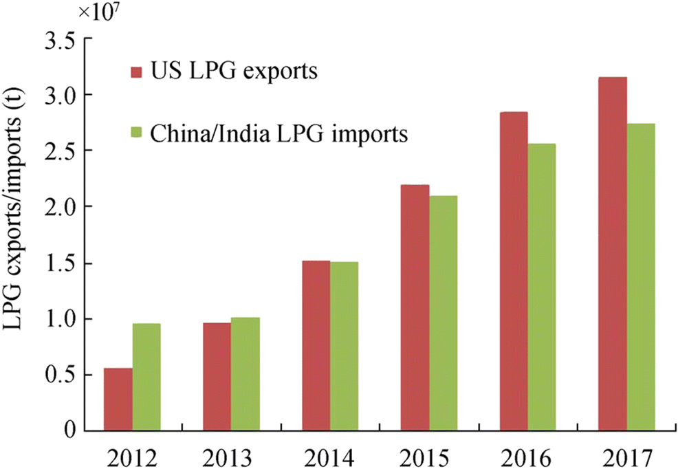
There is also a growing demand for other hydrocarbon gases, such as petroleum gases, ethylene, and ethane, but at a less rapid rate than natural gas demand. The LPG demand in Asia has grown considerably (Khurana 2017), and petroleum gas export from the USA increased by 39% over the 5-year period of 2012-2017 (Figure 2).
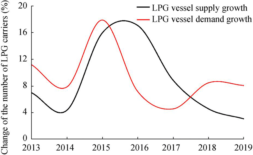
Therefore, there is an increased demand for gas carriers transporting petroleum gases (Khurana 2017); however, this demand is not met by the number of LPG carriers in service (Figure 3).
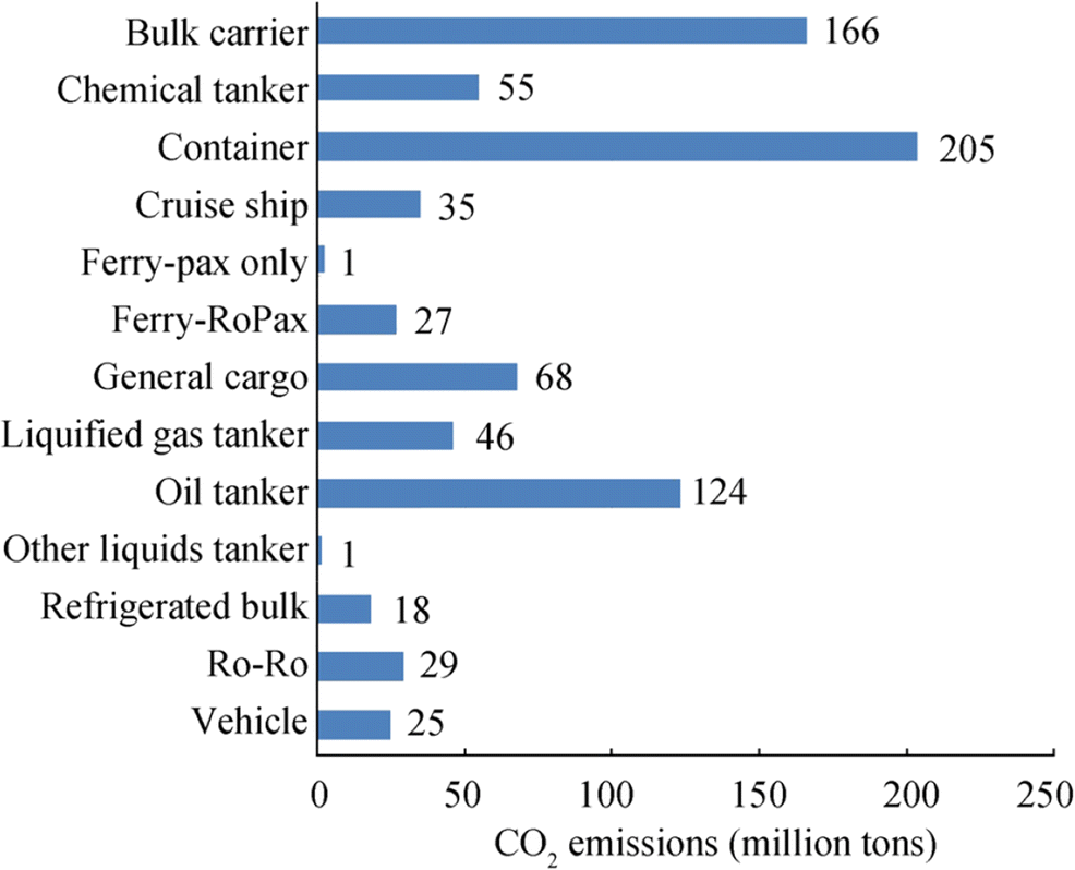
With regard to the level of CO2 emission controlled by IMO (IMO 2015), gas carriers rank sixth among all the types of ships (Figure. 4).
Most of the emission weight in 2012 (29%) could be attributed to gas carriers with cargo capacity from 50 000 to 200 000 m3. According to IMO (2015), this share will have increased by up to 66% by 2050. To estimate the emission level, the IMO report considers the following types of liquefied gas tankers distinguished by StatCode 5: LNG tankers, LPG tankers, CO2 tankers, and LPG/Chemical tankers.
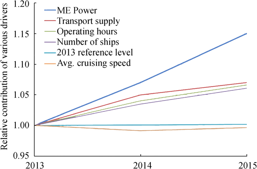
Between 2013 and 2015, the key factor responsible for the growth of carbon dioxide emission from gas carriers was an increase of the main engine power (Figure 5), whereas for other types of vessels, it was the transport supply expansion (Olmer et al. 2017).
The level of ship energy efficiency is determined by the EEDI and regulated by MARPOL 73/78 Annex VI, as well as other IMO regulations (IMO 2015). Wang et al. (2014) showed that carbon dioxide emission from LNG carriers is expected to grow by 280% from 2007 to 2040 without the EEDI introduction. Implementation of appropriate restrictions will reduce this growth to 200% during the reporting period. The most effective scenario is that the energy efficiency of all LNG carriers will be the same as that of the top 5% of ships in the industry as of 2011. In that case, carbon dioxide emission will have increased only by 130% by 2040.
3 Analysis of the Features of EEDI Calculation for Gas Carriers
The EEDI for new ships has been adopted in Annex VI of MARPOL 73/78. The attained EEDI for new ships is a measure of their energy efficiency (g/t∙nm) (IMO 2014). As the IMO is also a specialized agency of the United Nations responsible for regulating shipping, methods proposed in the IMO current regulations, as well as the estimation of ship energy efficiency, are accurate (IMO 2014, 2016a).
Regarding different types of gas carriers, the EEDI is applicable to LNG, CNG, LPG, and CO2 tankers. The formula for this index may not be applicable to LPG tankers that can additionally carry chemical products (IMO 2013).
Several groups of parameters have an impact on the attained EEDI: the ship's power plant parameters (main and auxiliary engine power, fuel type, and consumption) and sea-going qualities (deadweight or capacity, reference speed), as well as non-dimensional factors that consider the ship design features, region of navigation, and availability of innovative energy efficiency technologies (IMO 2014).
The attained EEDI is calculated by the following formula (IMO 2014):
$$ {\displaystyle \begin{array}{c}\mathrm{EEDI}=\frac{\left(\prod \limits_{j=1}^M{f}_j\right)\left(\sum \limits_{i=1}^{n\mathrm{ME}}{P}_{\mathrm{ME}(i)}\cdot {C}_{\mathrm{FME}(i)}\cdot {\mathrm{SFC}}_{\mathrm{ME}(i)}\right)}{f_i\cdot {f}_c\cdot {f}_l\cdot \mathrm{Capacity}\cdot {V}_{\mathrm{ref}}\cdot {f}_w}\\ {}+\frac{\left({P}_{\mathrm{AE}}\cdot {C}_{\mathrm{FAE}}\cdot {\mathrm{SFC}}_{\mathrm{AE}}\ast \right)}{f_i\cdot {f}_c\cdot {f}_l\cdot \mathrm{Capacity}\cdot {V}_{\mathrm{ref}}\cdot {f}_w}\\ {}+\frac{\left(\left(\prod \limits_{j=1}^M{f}_j\cdot \sum \limits_{i=1}^{n\mathrm{PTI}}{P}_{\mathrm{PTI}(i)}-\sum \limits_{i=1}^{n\mathrm{eff}}{f}_{\mathrm{eff}(i)}\cdot {P}_{\mathrm{AE}\mathrm{eff}(i)}\right){C}_{\mathrm{FAE}}\cdot {\mathrm{SFC}}_{\mathrm{AE}}\right)}{f_i\cdot {f}_c\cdot {f}_l\cdot \mathrm{Capacity}\cdot {V}_{\mathrm{ref}}\cdot {f}_w}\\ {}-\frac{\left(\sum \limits_{i=1}^{n\mathrm{eff}}{f}_{\mathrm{eff}(i)}\cdot {P}_{\mathrm{eff}(i)}\cdot {C}_{\mathrm{FME}}\cdot {\mathrm{SFC}}_{\mathrm{ME}}\right)}{f_i\cdot {f}_c\cdot {f}_l\cdot \mathrm{Capacity}\cdot {V}_{\mathrm{ref}}\cdot {f}_w}\end{array}} $$ (1) *If a part of the normal maximum sea load is provided by shaft generators, SFCME and CFME replace SFCAE and CFAE for that part of the power.
Here, SFС is the specific fuel consumption for main engines (ME) and auxiliary engines (AE), measured in g/kWh.
For gas carriers, deadweight should be used as Capacity.
Other elements of the formula include the following:
СF is a non-dimensional conversion factor between fuel consumption and CO2 emission measured in g, which is based on carbon content in the fuel; Vref is the ship speed measured in knots; PME(i) is the power of the ME measured in kW; PPTI(i) is 75% of the rated power consumption of each shaft motor divided by the weighted average efficiency of the generator(s), kW; Peff(i) is the output of the innovative mechanical energy-efficient technology for propulsion at 75% main engine power; PAEeff(i) is the auxiliary power reduction due to innovative electrical energy-efficient technology; PAE is the auxiliary engine power required to supply the normal maximum sea load; fj is a correction factor to account for a ship's specific design elements; fw is a non-dimensional coefficient indicating the decrease of speed in representative sea conditions; feff(i) is the availability factor of each innovative energy efficiency technology; fi is the capacity factor for any technical/regulatory limitation on capacity; fc is the cubic capacity correction factor; and fl is the factor for general cargo ships equipped with cranes and other cargo-related gear to compensate for deadweight losses (IMO 2014).
When calculating the EEDI, two types of gas carriers can be distinguished: LNG carriers and other gas carriers. The EEDI reference lines for these two types are calculated by different formulas. For LNG carriers, the formula is as follows:
$$ \mathrm{Reference}\ \mathrm{EEDI}=2253.7\times {\mathrm{DWT}}^{-0.474} $$ (2) while for other gas carriers, the formula is as follows:
$$ \mathrm{Reference}\ \mathrm{EEDI}=1120\times {\mathrm{DWT}}^{-0.456} $$ (3) where DWT denotes the difference between the displacement of a ship in water of 1.025 kg/m3 relative density at the summer load draught and the ship's lightweight. The EEDI reduction factors are intended to be introduced in phases over 2013 to 2025, becoming increasingly restrictive at each phase (Table 2) (IMO 2016b).
Table 2 EEDI reduction factors, cut off limits, and implementation phasesShip Type Size Phase 0: Jan 1, 2013-Dec 31, 2014 Phase 1: Jan 1, 2015-Dec 31, 2019 Phase 2: Jan 1, 2020-Dec 31, 2024 Phase 3: Jan 1, 2025, and onward LNG carriers 10 000 DWT and above - 10%* 20% 30% Gas carriers 10 000 DWT and above 0% 10% 20% 30% 2000-10 000 DWT - 0-10% 0-20% 0-30% *Phase 1 commences for those ships on September 1, 2015 Here, we will briefly cover some features of the attained EEDI calculation for gas carriers. The formula may not be applicable to ships with diesel-electric or turbine propulsion system, except for LNG carriers. Accordingly, the estimations of the rated installed power of ME for various types of propulsion systems are different. Thus, PME(i) is 75% of the rated installed power for each main engine for diesel-mechanical propulsion systems and 83% for ST propulsion systems. For LNG carriers with a diesel-electric propulsion system, PME(i) should be calculated using the following formula:
$$ {P}_{\mathrm{ME}(i)}=0.83\times \frac{{\mathrm{MPP}}_{\mathrm{Motor}(i)}}{\eta_{(i)}} $$ (4) where MPPMotor(i) is the rated motor output given in the certified document, and η(i) is the product of the electrical efficiencies of the generator, transformer, converter, and motor.
It is worth noting that STs have restricted use as propulsion systems on modern LNG carriers because of several disadvantages. The most crucial of them include lower efficiency and higher mass and dimensional characteristics compared with those of diesel engines (Norberg 2012; Lin et al. 2014).
Another feature of the attained EEDI calculation is the estimation of PAE for LNG carriers with a re-liquefaction system or compressors for supplying BOG-derived high-pressure or low-pressure gas to the installed engines. For ships having a ST propulsion system, where electric power is primarily supplied by a turbine generator closely integrated into the steam and feed water systems, PAE is taken equal to 0.
For LNG carriers with direct or electrical transmission, PAE is calculated as follows:
$$ {P}_{\mathrm{AE}}=\left(0.025\times \left(\sum \limits_{i=1}^{n\mathrm{ME}}{\mathrm{MCR}}_{\mathrm{ME}(i)}+\frac{\sum \limits_{i=1}^{n\mathrm{PTI}}{P}_{\mathrm{PTI}(i)}}{0.75}\right)\right)+250 $$ Moreover, one of the three equations below can be added:
$$ {\displaystyle \begin{array}{l}{\mathrm{CargoTankCapacity}}_{\mathrm{LNG}}\times \mathrm{BOR}\times {\mathrm{COP}}_{\mathrm{reliquefy}}\times {R}_{\mathrm{reliquefy}},\\ {}{\mathrm{COP}}_{\mathrm{comp}}\times \sum \limits_{i=1}^{n\mathrm{ME}}{\mathrm{SFC}}_{\mathrm{ME}(i),\mathrm{gasmode}}\times \frac{P_{\mathrm{ME}(i)}}{1000},\\ {}0.02\times \sum \limits_{i=1}^{n\mathrm{ME}}{P}_{\mathrm{ME}(i)}\end{array}} $$ (5) where CargoTankCapacityLNG is the LNG cargo tank capacity in m3; BOR is the design BOG rate of the entire ship per day; COPreliquefy is the coefficient of design power performance for re-liquefying BOG per unit volume; Rreliquefy is the ratio of the BOG volume to be re-liquefied to the entire volume of BOG, COPcomp is the design power performance of compressor, and 0.33 (kWh/kg) should be used.
There are certain peculiarities of fuel consumption calculation for steam propulsion systems and dual-fuel engines operating on fuel oils and natural gas (Wang et al. 2014):
$$ {\mathrm{SFC}}_{\mathrm{SteamTurbine}}=\frac{\mathrm{FuelConsumption}}{\sum \limits_{i=1}^{n\mathrm{ME}}{P}_{\mathrm{ME}(i)}} $$ (6) The capacity correction factor, fi, is taken equal to 1, except for ice-class ships. For ice-class ships, particular formulas are employed to calculate fi for various ship types, including LNG carriers. The same applies to the power correction factor fj.
The cubic correction factor, fc, is taken equal to 1 as well. However, for LNG carriers with a direct diesel-driven propulsion system, the following cubic capacity correction factor fcLNG should be applied:
$$ {f}_{c\mathrm{LNG}}={R}^{-0.56} $$ (7) where R is the capacity ratio of the deadweight of the ship (tons) divided by the total cubic capacity of the cargo tanks of the ship (m3).
Therefore, EEDI calculation has distinctive features for ice-class LNG carriers, LNG carriers with various propulsion systems (direct diesel-driven, diesel-electrical, ST), those with dual-fuel engines operating on fuel oils and natural gas, and those with a re-liquefaction system or compressors for supplying pressured gas.
4 Study of EEDI Calculation for Modern Gas Carriers
The attained EEDI calculation for various ship types has been considered in many studies. For instance, in one study, the EEDI was calculated for 381 gas carriers built over 2009-2016 (CE Delft 2017). Despite the significant sample size, a drawback of this study is the lack of differentiation by type of propulsion system and cargo. These key factors may have a major impact on the attained EEDI.
Here, we calculate the EEDI for eligible modern gas carriers. Ship designs have been selected from the Significant Ships issues published by the Royal Institution of Naval Architects in 2011-2017 (RINA 2012, 2013, 2014, 2015, 2016, 2017, 2018). This annual publication contains information about the designs delivered by shipyards over the year worldwide, which are the most interesting per experts' opinions. The designs comprise a reasonably representative sample, which allows determining major trends in the use of various shipbuilding technologies.
The sample includes 30 ships eligible for EEDI calculation, 13 of which are LPG carriers, and the remaining 17 are LNG carriers. All the selected LPG carriers are equipped with main low-speed diesel engines. While four out of 17 LNG carriers are equipped with steam turbine propulsion systems (ST and UST), the rest are equipped with diesel propulsion systems. All diesel engines are DF. Only one LNG carrier has a direct diesel-driven propulsion system with a low-speed engine, while other ships with diesel propulsion systems have main medium-speed engines, two of which are DF D4S M LP and 10 (RINA 2012, 2013, 2014, 2015, 2016, 2017, 2018).
Calculations have been conducted according to the method presented in IMO (2014), and the recommendations and clarifications given in Class NK (2014), Class NK (2016), and IACS (2016) were followed.
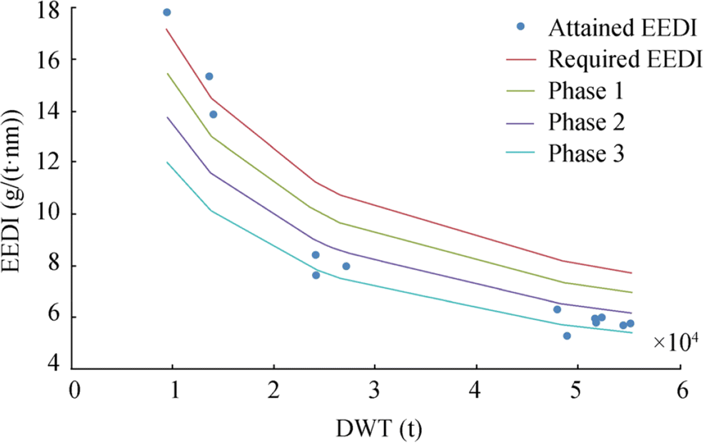
The results of the EEDI calculations for LPG carriers operating on fuel oils are illustrated in Figure 6. The attained EEDI is compared with reference lines for all implementation phases. As can be seen, the majority of the selected modern LPG carriers comply with the EEDI requirements, except for two low-displacement ships, and another two ships even exceed the requirements of the most stringent Phase 3.
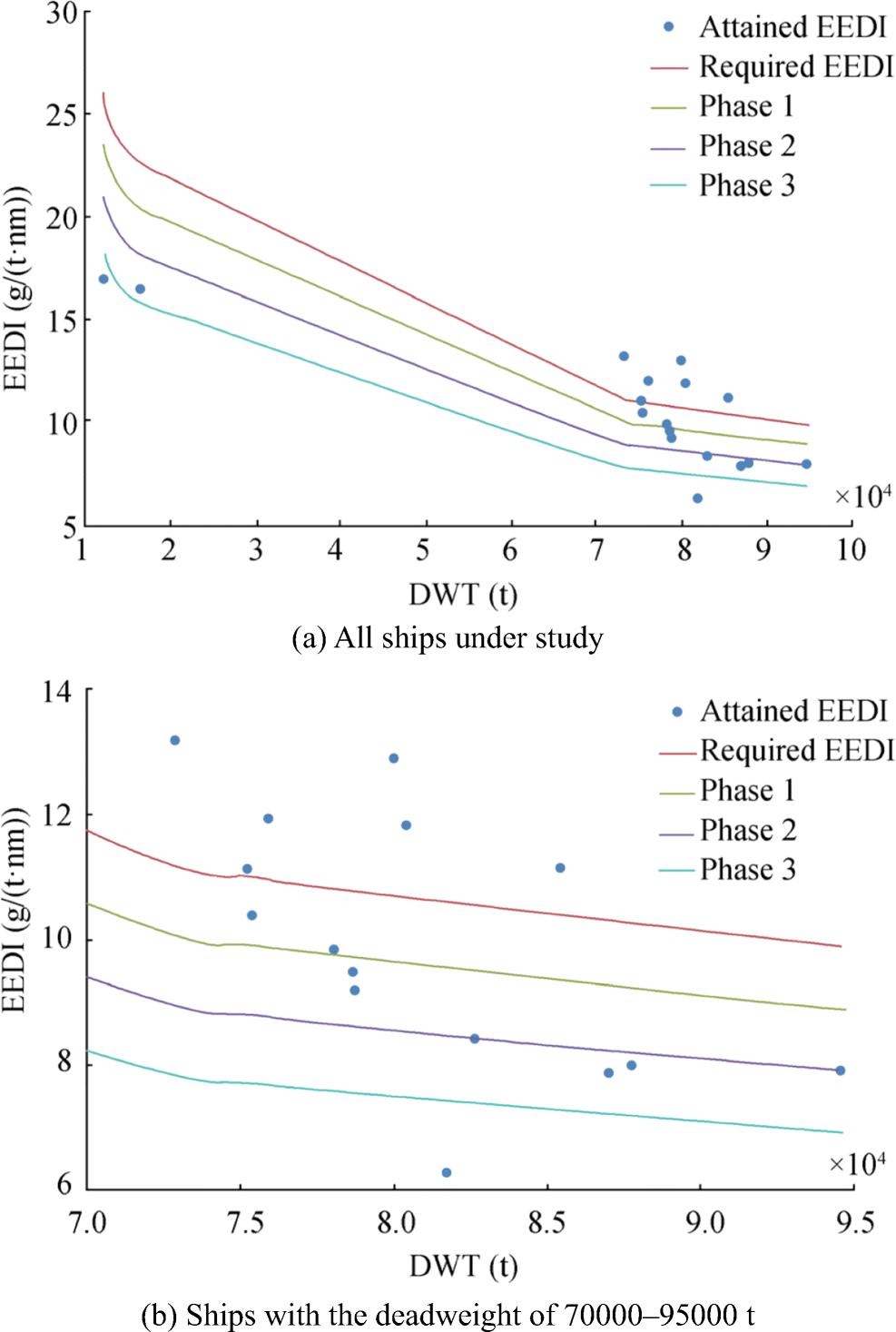
Similar graphs for LNG carriers operating on fuel oils are shown in Figure 7. The majority of ships under study have a deadweight of 70 000-95 000 tons; for illustrative purposes, this group of ships is shown separately in Figure 7b. As seen in Figure 7, six LNG carriers do not comply with the EEDI requirements, and four of them have ST propulsion systems. However, there are studies that show an opportunity to increase the efficiency and overall energy performance of LNG carriers by improving the STs, including the use of superheated steam (Oka et al. 2004; Sato and Chung 2013). Installation of STs as ship ME can also significantly lower the NOx emission in comparison with diesel engines (Oka et al. 2004; Bengt and Knut, 2011).
A comparison of the EEDI data for LNG carriers operating on fuel oils and natural gas is shown in Figure 8. The attained EEDI for ships operating on natural gas complies with the EEDI requirements. However, even operation on natural gas cannot ensure the compliance of some gas carriers with the EEDI requirements of the most stringent Phase 3.
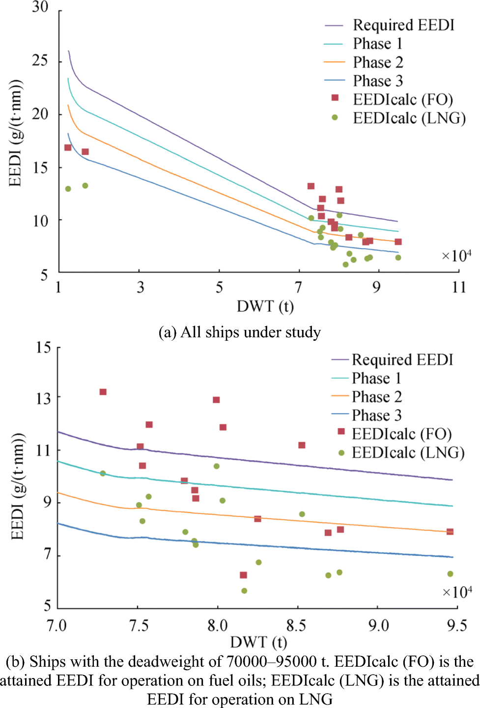 Figure 8 Comparison of the attained EEDI and the EEDI reference lines for LNG carriers operating on various fuels. (a) All ships under study. (b) Ships with the deadweight of 70 000-95 000 t. EEDIcalc (FO) is the attained EEDI for operation on fuel oils; EEDIcalc (LNG) is the attained EEDI for operation on LNG
Data analysis has shown that the majority of the investigated gas carriers built in 2011-2017 meet the EEDI requirements of at least Phase 1, considering the period of their construction. However, many cargo ships are built in series. Accordingly, gas carriers with the same parameters but built after 2020 and 2025 will not be able to meet the requirements of the stringent Phase 2 and Phase 3 by operating on natural gas only. A promising solution for reducing carbon dioxide emission is the application of TCRs fed by main engine exhaust gases. The operation of ME on syngas generated in such a way will improve the energy efficiency of gas carriers. This is particularly relevant for LPG carriers, where direct engine feeding with BOG is not always possible. The operation of marine engines on heavy hydrocarbons (e.g., propane, butane), in contrast to methane, is still quite limited (Class NK, 2018; Bureau Veritas 2016).
Besides lower CO2 emission, operation on natural gas leads to higher emission of another greenhouse gas, methane (so-called methane slip) (Ghadikolaei et al. 2016). The use of TCRs on board gas carriers can solve this issue. Although methane as an emission component is not controlled at the legislative level yet, an increase in the number of ships operating on natural and other hydrocarbon gases may foreground the issue. Some researchers are working on this issue and propose including methane slip in the EEDI formula by introducing new coefficients for LNG carriers (Roy 2016).
5 Study of the Impact of Thermochemical Technologies of Waste Heat Recovery on EEDI Reduction
To ensure the efficiency of thermochemical technologies of waste heat recovery, it is required that the temperature and power potentials are sufficient for the production of the relevant quantity and quality of syngas from basic fuel.
Previous studies (Cherednichenko 2015; Cherednichenko and Serbin 2018) have identified promising types of power plants for gas carriers that suggest the application of thermochemical technologies of waste heat recovery.
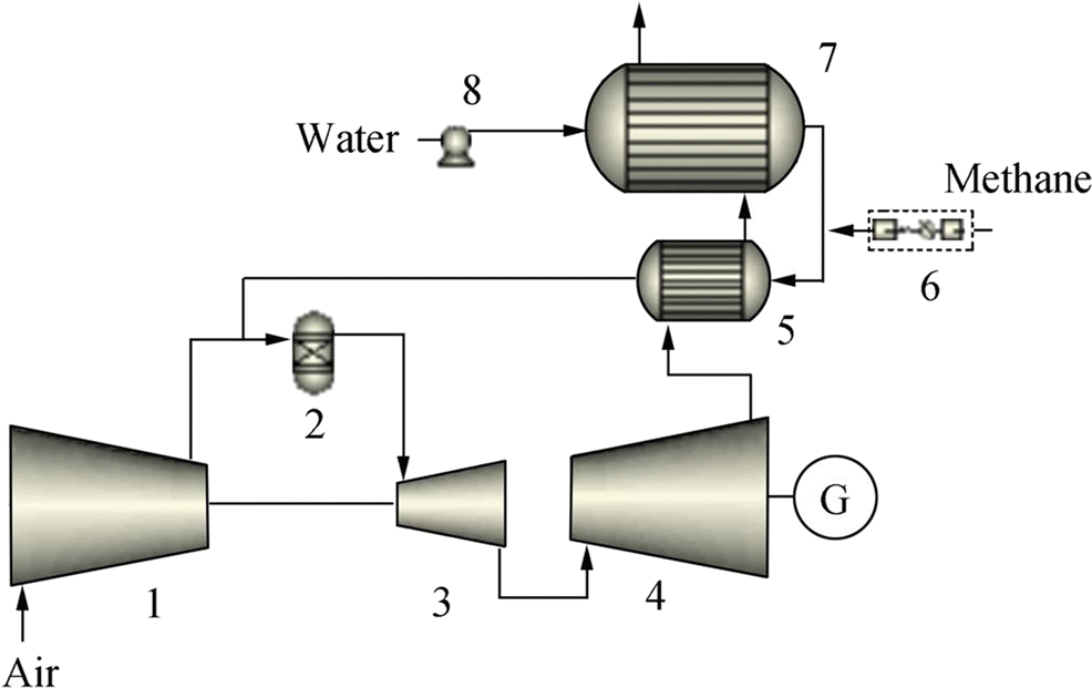
The method of mathematical modeling has been applied to analyze the characteristics of the combined gas-turbine-electric and diesel-electric power plants with thermochemical recuperation of the exhaust gas heat via steam conversion of natural/petroleum gas or cargo evaporation products COGED (DF D4S GT E LP) with TCRs.
One of the promising ways for the thermochemical conversion of organic raw materials into syngas is the plasma-chemical method (Gatsenko and Serbin 1995; Serbin 1998; Matveev et al. 2007a, b, 2008). It can be implemented in power plants of various types (Serbin 2006; Matveev and Serbin 2006). Plasma-assisted thermochemical transformations can be used directly for hydrocarbon fuel treatment; in addition, plasma assistance is applicable for intensifying the combustion processes of syngas produced with thermochemical technology (Serbin et al. 2014; Matveev et al. 2007a, b; Matveev and Serbin 2012).
As indicated by numerous studies, the application of TCRs (including the plasma-chemical method) ensures not only a decrease in specific fuel consumption in the propulsion system but also a significant reduction in carbon dioxide generated at fuel combustion (its amount is defined by the carbon content in the fuel).
The impacts of changes in climatic conditions on the efficiency of waste heat recovery processes have been comprehensively studied by Radchenko et al. (2018, 2019).
Carbon content can be calculated using the following methodology (API 2013):
$$ {\mathrm{CC}}_{\mathrm{Mixture}}=\frac{\sum \limits_{i=1}^{\#\mathrm{of}\_\mathrm{Components}}\left(n\times {\mathrm{AW}}_{\mathrm{Carbon}}\times {Xm}_i\right)}{\sum \limits_{i=1}^{\#\mathrm{of}\_\mathrm{Components}}\left({\mathrm{MW}}_i\times {Xm}_i\right)} $$ (8) where CCMixture is the carbon content weight fraction of the mixture; n is the number of carbon atoms in the component; AWCarbon is the atomic weight of carbon; MWi is the molecular weight of component i; and Xmi is the mole fraction.
The main components of syngas formed during steam conversion of hydrocarbon fuel are H2, H2O, CH4, CO2, and CO.
Table 3 provides the results of carbon content calculation for the syngas formed during steam conversion via the thermochemical recuperation of exhaust gas heat in the GT engine Siemens SGT 400 (Figure 9). The exhaust gas temperature is 555°С. According to Alves and Nebra (2003), the steam-to-methane mole ratio is ≈7. The calculation was carried out using dry components. The molar masses were taken according to Dean (1999).
Table 3 Carbon content calculation for syngasParameters CO CO2 CH4 H2 Mole fraction Xm 0.0063 0.1262 0.3439 0.5236 Molar mass MW 28.0101 44.0095 16.0425 16.0425 No. of carbon atoms in the component n 1 1 1 0 Atomic weight of carbon AWCarbon 12.0107 12.0107 12.0107 12.0107 n × AWCarbon × Xm 0.0757 1.5158 4.1305 0.0000 Xm × MW 0.1765 5.5540 5.5170 0.5277 Sum of (n × AWCarbon × Xm) 5.7219 Sum of (Xm × MW) 11.7752 Carbon content CC 0.4859 The analysis of the results indicates that methane conversion in such conditions leads to 35% reduction of the carbon content, and the waste heat of the main engine is recovered.
Table 4 and Table 5 provide the calculation results of molar fraction, carbon content, and lower calorific value for the syngas formed during steam conversion of natural gas, ethane, propane, and butane via thermochemical recuperation of exhaust gas heat in the GT engine Siemens SGT 400.
Table 4 Mole fraction calculation for the syngas formed during steam conversionComponent Fuel LNG (Benito 2009) Ethane Propane Butane CO 0.00655 0.0014 0.0111 0.0119 CO2 0.13345 0.1474 0.1864 0.2037 CH4 0.3693 0.6637 0.54 0.5316 H2 0.4884 0.1875 0.2625 0.2528 Nitrogen 0.00224 - - - Table 5 Carbon content and lower calorific value calculation for the syngas formed during steam conversionFuel LNG (Heavy) (Benito 2009) Ethane Propane Butane Carbon content 0.4880 0.5621 0.5079 0.4964 Carbon content reduction (%) 34.9 29.6 37.8 39.9 Lower calorific value (MJ/kg) 53.7 58.2 59.2 59.0 Lower calorific value increase (%) 10 23 28 29 Here, mathematical modeling is employed to analyze the efficiency of power plant modernization for one of the most advanced and innovative projects, the Arctic LNG carrier Christophe de Margerie (size class of 170 000 m).
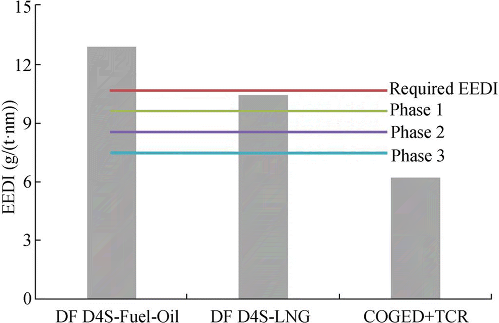
The basic power plant with a total output of 64.35 MW has the DF D4S E LP design. It consists of six Wartsila diesel engines, including four 12V50DF engines (11.7 MW each) and two 9L50DF engines (8.775 MW each) (RINA 2017). Calculations show that the attained EEDI is 12.89 g/(t·nm) when the engines operate on fuel oils and 10.4 g/(t·m) when they operate on BOG.
The alternative power plant COGED (DF D4S GT E LP) with TCR and total output of 65.55 MW consists of one gas-turbine engine, Siemens SGT 400, with an output of 12.9 MW, and five Wartsila diesel engines (three 12V50DF and two 9L50DF). The main advantages of gas turbines used in ice-class ships are the following: a high capability for quick start-up and load pickup (from 2 to 5 min), which is essential in the Arctic; low mass and dimensional characteristics at a sufficiently high power per one GT engine; the capability of long-term steady engine operation on nominal mode; the possibility of engine tuning for operation at subzero air temperatures; and the possibility of unit replacement during repair.
Calculations demonstrate that despite the application of a GT engine with a considerably lower efficiency than a diesel engine, the total efficiency of the power plant is almost the same and makes up 49% on engine flanges.
This is because TCR utilization can reduce specific fuel consumption in the power plant engine by 7%. Thus, the SFC is 0.137 kg/(kW·h) for diesel engines and 0.189 kg/(kW·h) for GT engines. Because of relatively low temperatures in the Arctic, a higher engine efficiency is expected for all the options of GT applications.
Although the hourly fuel consumptions for the basic and alternative plants are almost the same (9.5 tons per hour), TCR utilization can significantly decrease the EEDI by reducing the carbon content in the fuel. According to the calculations, the attained EEDI for the alternative plant is 6.18 g/(t·nm). The EEDI data for various options are compared in Figure 10 below.
As can be seen in Figure 10, even operation on BOG (methane) cannot ensure the energy efficiency of LNG carriers built in 2017, and the carriers are thus subject to the Phase 1 requirements. However, EEDI declines by 20% in this case compared with the EEDI associated with operation on fuel oils. Meanwhile, the application of the COGED with TCR ensures the energy efficiency of LNG carriers at the level of the most stringent requirements for carbon emission, which almost halves.
6 Conclusion
As shown by the calculation of the attained EEDI for 13 considered modern LPG carriers, 11 ships comply with the EEDI requirements, but only two of them meet the requirements of the most stringent Phase 3.
Moreover, 6 of the 17 considered LNG carriers do not comply with the EEDI requirements when operating on fuel oils, including all those with ST propulsion systems. When the ships operate on natural gas (BOG), all of them comply with the requirements of Phase 0 the least, and eight of them meet the requirements of Phase 3. Meanwhile, only two LNG carriers do so when operating on fuel oils.
At the same time, the utilization of natural gas as fuel for gas carriers cannot always ensure a high energy efficiency. A promising solution of carbon emission reduction is the application of TCRs fed by main engine exhaust gases.
As indicated by the results of mathematical modeling of the conversion of the main LNG and LPG components, the carbon content in syngas can be decreased on average by 30%-40%, while the lower calorific value can be increased by 30%.
The utilization of TCR on gas carriers with engines fueled by syngas produced from BOG will provide the IMO-required energy efficiency without the use of other energy-efficient technologies. This makes TCR application quite promising for the group of ships under study.
Open Access This article is licensed under a Creative Commons Attribution 4.0 International License, which permits use, sharing, adaptation, distribution and reproduction in any medium or format, as long as you give appropriate credit to the original author(s) and the source, provide a link to the Creative Commons licence, and indicate if changes were made. The images or other third party material in this article are included in the article's Creative Commons licence, unless indicated otherwise in a credit line to the material. If material is not included in the article's Creative Commons licence and your intended use is not permitted by statutory regulation or exceeds the permitted use, you will need to obtain permission directly from the copyright holder. To view a copy of this licence, visit http://creativecommons.org/licenses/by/4.0/. -
Figure 8 Comparison of the attained EEDI and the EEDI reference lines for LNG carriers operating on various fuels. (a) All ships under study. (b) Ships with the deadweight of 70 000-95 000 t. EEDIcalc (FO) is the attained EEDI for operation on fuel oils; EEDIcalc (LNG) is the attained EEDI for operation on LNG
Table 1 LNG industry growth over the past 20 years
Parameters 1993 2003 2013 Liquefaction plants 11 15 26 Receiving terminals 31 46 104 LNG carriers 76 152 393 Number of importing countries 9 13 29 LNG imports (million tons) 61.0 125.2 236.9 Table 2 EEDI reduction factors, cut off limits, and implementation phases
Ship Type Size Phase 0: Jan 1, 2013-Dec 31, 2014 Phase 1: Jan 1, 2015-Dec 31, 2019 Phase 2: Jan 1, 2020-Dec 31, 2024 Phase 3: Jan 1, 2025, and onward LNG carriers 10 000 DWT and above - 10%* 20% 30% Gas carriers 10 000 DWT and above 0% 10% 20% 30% 2000-10 000 DWT - 0-10% 0-20% 0-30% *Phase 1 commences for those ships on September 1, 2015 Table 3 Carbon content calculation for syngas
Parameters CO CO2 CH4 H2 Mole fraction Xm 0.0063 0.1262 0.3439 0.5236 Molar mass MW 28.0101 44.0095 16.0425 16.0425 No. of carbon atoms in the component n 1 1 1 0 Atomic weight of carbon AWCarbon 12.0107 12.0107 12.0107 12.0107 n × AWCarbon × Xm 0.0757 1.5158 4.1305 0.0000 Xm × MW 0.1765 5.5540 5.5170 0.5277 Sum of (n × AWCarbon × Xm) 5.7219 Sum of (Xm × MW) 11.7752 Carbon content CC 0.4859 Table 4 Mole fraction calculation for the syngas formed during steam conversion
Component Fuel LNG (Benito 2009) Ethane Propane Butane CO 0.00655 0.0014 0.0111 0.0119 CO2 0.13345 0.1474 0.1864 0.2037 CH4 0.3693 0.6637 0.54 0.5316 H2 0.4884 0.1875 0.2625 0.2528 Nitrogen 0.00224 - - - Table 5 Carbon content and lower calorific value calculation for the syngas formed during steam conversion
Fuel LNG (Heavy) (Benito 2009) Ethane Propane Butane Carbon content 0.4880 0.5621 0.5079 0.4964 Carbon content reduction (%) 34.9 29.6 37.8 39.9 Lower calorific value (MJ/kg) 53.7 58.2 59.2 59.0 Lower calorific value increase (%) 10 23 28 29 -
Adeosun M (2017) Will new LNG trade routes support demand for LNG carriers? Available from: http://www.maritime-executive.com/editorials/will-new-lng-trade-routes-support-demand-for-lng-carriers [accessed on march. 10, 2019] Alves LG, Nebra SA (2003) Thermoeconomic evaluation of a basic optimized chemically recuperated gas turbine cycle. Int J Thermodynamics 6(1): 13-22. https://doi.org/10.5541/ijot.103 API (2013) Carbon content, sampling, and calculation. American Petroleum Institute, API TR 2572 Bengt ON, Knut AM (2011) Energy efficiency and CO2 emissions in LNG chains. 2nd Trondheim Gas Technology Conference, 4-6 Benito A (2009) Accurate determination of LNG quality unloaded in receiving terminals an innovative approach. IGU. Buenos Aires, 1-23 BP (2018) BP energy outlook Bureau Veritas (2016) LPG carriers. Trust the safety experts CE Delft (2017) Estimated index values of ships 2009-2016. Analysis of the design efficiency of ships that have entered the fleet since 2009. Publication code: 17.7L97.69, 17-19 Cherednichenko O (2015) Analysis of efficiency of diesel-gas turbine power plant with thermo-chemical heat recovery. MOTROL. Komisja Motoryzacji i Energetyki Rolnictwa 17(2): 25-28 Cherednichenko O, Serbin S (2018) Analysis of efficiency of the ship propulsion system with thermochemical recuperation of waste heat. J Mar Sci Appl 17: 122-130. https://doi.org/10.1007/s11804-018-0012-x Class NK (2014) Introduction to the outcomes of MEPC 66. Japan technical information No. TEC-0991, Tokyo Class NK (2016) IACS procedural requirement no. 38 (rev. 1) in relation to energy efficiency design index (EEDI). Japan technical information No. TEC-1073, Tokyo Class NK (2018) Alternative fuels and energy efficiency for the shipping industry: an overview of LNG, LPG and methanol fuelled ships. Available from https://gmn.imo.org/wp-content/uploads/2018/01/AnnexV-2-5-Alternative-Fuels-and-Energy-Efficiency.pdf [accessed on march. 10, 2019] Dean JA (1999) LANGE'S handbook of chemistry, Fifteenth edn. McGrawHill, Inc., New York City Fernández IA, Gómez MR, Gómez JR, Insua AB (2017) Review of propulsion systems on LNG carriers. Renew Sust Energ Rev 67: 1395-1411. https://doi.org/10.1016/j.rser.2016.09.095 Gatsenko NA, Serbin SI (1995) Arc plasmatrons for burning fuel in industrial installations. Glas Ceram 51(11-12): 383-386 Ghadikolaei MA, Cheung CH, Yung KF (2016) Study of performance and emissions of marine engines fueled with liquefied natural gas (LNG). 2016 proceedings of 7th PAAMES and AMEC2016, Hong Kong Głomski P, Michalski R (2011) Problems with determination of evaporation rate and properties of boil-off gas on board LNG carriers. J. Pol. CIMAC: Energetic Aspects 6(1): 133-140. https://doi.org/10.7225/toms.v02.n02.001 Gomez JR, Gomez MR, Garcia RF, De Miguel A (2014) On board LNG reliquefaction technology: a comparative study. Pol Marit Res 21: 77-88. https://doi.org/10.2478/pomr-2014-0011 Hiramatsu S, Kuwahata K, Hirota K, Ishida T, Tsukamoto H, Ishibashi K (2016) SAYARINGO STaGE - next generation MOSS-type LNG carrier with hybrid propulsion plant. Mitsubishi Heavy Ind Tech Rev 53(2): 3-10 IACS (2016) Procedure for calculation and verification of the energy efficiency design index (EEDI). International Association of Classification Societies, London No. 38 IGU (2018) IGU world LNG report — 2018 edition. Available from: https://www.igu.org/sites/default/files/node-document-field_file/IGU_LNG_2018_0.pdf [Accessed on March. 10, 2019] IMO (2013) Guidelines for calculation of reference lines for use with the Energy Efficiency Design Index (EEDI). MEPC. 231(65). MEPC 65/22/Ann. 14 p: 1 IMO (2014) Guidelines on the method of calculation of the attained energy efficiency design index (EEDI) for new ships. MEPC. 245(66). MEPC 66/21/Add. 1 p: 1 IMO (2015) Third IMO GHG study 2014. Executive summary and final report. International Maritime Organization, London IMO (2016a) Amendments to the 2014 guidelines on the method of calculation of the attained energy efficiency design index (EEDI) for new ships. MEPC. 281(70). MEPC 70/18/Add. 1 p: 1 IMO (2016b) Train the trainer (TTT) course on energy efficient ship operation. Module 2 - Ship energy efficiency regulations and related guidelines Karabetsou C, Tzannatos ES (2003) LNG changes in the context of the expanding market of natural gas. Eur Res Stud VI(3-4): 67-84 Khurana G (2017) Global shipping markets. Capital link Greek shipping forum. Available from: http://forums.capitallink.Com/shipping/2018greece//ppt/khurana.Pdf [accessed on march. 10, 2019] Lin Y, Yu Y, Guan G (2014) Research on energy efficiency design index for sea-going LNG carriers. J Mar Sci Appl 13: 430-436. https://doi.org/10.1007/s11804-014-1282-6 MAN Diesel & Turbo (2013) Propulsion trends in LNG carriers. MAN Diesel & Turbo, Copenhagen, Denmark Available from: https://www.scribd.com/document/255681462/Propulsion-Trends-in -Lng-Carriers [Accessed on March. 10, 2019] Matveev I, Serbin S (2006) Experimental and numerical definition of the reverse vortex combustor parameters. 44th AIAA Aerospace Sciences Meeting and Exhibit, Reno, AIAA-2006-0551, 6662-6673 Matveev I, Serbin S (2012) Investigation of a reverse-vortex plasma assisted combustion system. Proc. of the ASME 2012 Heat Transfer Summer Conf., Puerto Rico, HT2012-58037, 133-140 Matveev I, Matveeva S, Serbin S (2007a) Design and preliminary result of the plasma assisted tornado combustor. Collection of Technical Papers - 43rd AIAA/ASME/SAE/ASEE Joint Propulsion Conference, Cincinnati, AIAA 2007-5628, 6, 6091-6098 Matveev I, Serbin S, Mostipanenko A (2007b) Numerical optimization of the "tornado" combustor aerodynamic parameters. Collection of Technical Papers - 45th AIAA Aerospace Sciences Meeting, Reno, AIAA 2007-391, 4744-4755 Matveev IB, Tropina AA, Serbin SI, Kostyuk VY (2008) Arc modeling in a plasmatron channel. IEEE Trans Plasma Sci 36(1): 293-298 https://doi.org/10.1109/TPS.2007.913876 Norberg A (2012) Interrelationships of LNG cargo containment systems and machinery configurations on LNG carrier - design and operational factors with economic assessment. Master thesis, Norwegian University of Science and Technology, Trondheim, 56-62 Oka M, Hiraoka K, Tsumura K (2004) Development of next-generation LNGC propulsion plant and HYBRID system. Mitsubishi Heavy Industries, Ltd Technical Review, 41(6), 1-5 Olmer N, Comer B, Roy B, Mao X, Rutherford D (2017) Greenhouse gas emissions from global shipping, 2013-2015. International Council on Clean Transportation, Washington D. C. Outlook for Energy (2018) Outlook for energy: A view to 2040. ExxonMobil, Available from: https://cdn.exxonmobil.com/~/media/global/files/outlook-for-energy/2018/2018-outlook-for-energy.pdf [Accessed on March. 10, 2019] Radchenko R, Radchenko A, Serbin S, Kantor S, Portnoi B (2018) Gas turbine unite inlet air cooling by using an excessive refrigeration capacity of absorption-ejector chiller in booster air cooler. E3S Web of Conferences, vol. 70, No. 03012 Radchenko M, Radchenko R, Ostapenko O, Zubarev A, Hrych A (2019) Enhancing the utilization of gas engine module exhaust heat by two-stage chillers for combined electricity, heat and refrigeration. 5th International Conference on Systems and Informatics ICSAI 2018, no. 8599492, 240-244 RINA (2012) Significant ships of 2011. The Royal Institution of Naval Architects, London, pp 36-90 RINA (2013) Significant ships of 2012. The Royal Institution of Naval Architects, London, pp 20-34 RINA (2014) Significant ships of 2013. The Royal Institution of Naval Architects, London, pp 34-108 RINA (2015) Significant ships of 2014. The Royal Institution of Naval Architects, London, pp 8-121 RINA (2016) Significant ships of 2015. The Royal Institution of Naval Architects, London, pp 38-74 RINA (2017) Significant ships of 2016. The Royal Institution of Naval Architects, London, pp 32-88 RINA (2018) Significant ships of 2017. The Royal Institution of Naval Architects, London, pp 20-80 Roy B (2016) Energy efficiency regulations for LNG carriers. International Council on Clean Transportation Sato K, Chung H (2013. Design of the evolutionary LNG carrier "Sayaendo". 17th International Conference & Exhibition on Liquefied Natural Gas (LNG 17), Houston. Available from: https://pdfs.semanticscholar.org/8c19/8a9daa131fcfc909a557e6f1ad7d07b6d378.pdf [accessed on march. 10, 2019] Serbin SI (1998) Modeling and experimental study of operation process in a gas turbine combustor with a plasma-chemical element. Combust Sci Technol 139: 137-158 https://doi.org/10.1080/00102209808952084 Serbin SI (2006) Features of liquid-fuel plasma-chemical gasification for diesel engines. IEEE Trans Plasma Sci 34(6): 2488-2496 https://doi.org/10.1109/TPS.2006.876422 Serbin SI, Matveev IB, Goncharova MA (2014) Plasma assisted reforming of natural gas for GTL: part I. IEEE Trans Plasma Sci 42(12): 3896-3900 https://doi.org/10.1109/TPS.2014.2353042 SIGTTO (2014) LNG shipping at 50. A commemorative SIGTTO/GIIGNL publication US Energy Information Administration (2017) International energy outlook 2017. Available from: https://www.eia.gov/outlooks/ieo/pdf/0484(2017).pdf [Accessed on March. 10, 2019] Wang H, Rutherford D, Desai C (2014) Long-term energy efficiency improvement for LNG carriers. International Council on Clean Transportation, Washington D. C. Westwood Global Energy Group (2018) World LNG market forecast 2018-2022

