Hydrodynamic and Hydroacoustic Computational Prediction of Conventional and Highly Skewed Marine Propellers Operating in Non-uniform Ship Wake
https://doi.org/10.1007/s11804-020-00126-6
-
Abstract
Despite their high manufacturing cost and structural deficiencies especially in tip regions, highly skewed propellers are preferred in the marine industry, where underwater noise is a significant design criterion. However, hydrodynamic performances should also be considered before a decision to use these propellers is made. This study investigates the trade-off between hydrodynamic and hydroacoustic performances by comparing conventional and highly skewed Seiun Maru marine propellers for a noncavitating case. Many papers in the literature focus solely on hydroacoustic calculations for the open-water case. However, propulsive characteristics are significantly different when propeller-hull interactions take place. Changes in propulsion performance also reflect on the hydroacoustic performances of the propeller. In this study, propeller-hull interactions were considered to calculate the noise spectra. Rather than solving the full case, which is computationally demanding, an indirect approach was adopted; axial velocities from the nominal ship wake were introduced as the inlet condition of the numerical approach. A hybrid method based on the acoustic analogy was used in coupling computational fluid dynamics techniques with acoustic propagation methods, implementing the Ffowcs Williams-Hawkings (FW-H) equation. The hydrodynamic performances of both propellers were presented as a preliminary study. Propeller-hull interactions were included in calculations after observing good accordance between our results, experiments, and quasi-continuous method for the open-water case. With the use of the time-dependent flow field data of the propeller behind a non-uniform ship wake as an input, simulation results were used to solve the FW-H equation to extract acoustic pressure and sound pressure levels for several hydrophones located in the near field. Noise spectra results confirm that the highest values of the sound pressure levels are in the low-frequency range and the first harmonics calculated by the present method are in good accordance with the theoretical values. Results also show that a highly skewed propeller generates less noise even in noncavitating cases despite a small reduction in hydrodynamic efficiency.Article Highlights• Highly skewed propellers are generally used for better acoustic performance, but their hydrodynamic performances should also be considered.• The trade-off between hydrodynamic and hydroacoustic performances is investigated by comparing conventional and highly skewed marine propellers.• Highly skewed propellers generate less noise even in noncavitating cases although a small reduction in hydrodynamic efficiency is noted. -
1 Introduction
Ships produce significant noise levels, thus ruining the marine habitat in the oceans. One of the most affected fish is the blue whale because their communication at low frequencies coincides with the acoustic wakes of ship propellers. Changes in blue whales' call level and rate were observed in seas where heavy marine traffic was found (McKenna 2011). The daily lives of other marine animals were also reported to be affected, from searching for food to avoiding danger (Dekeling 2014), resulting in a change of residence, and loss of their original habitat.
The International Maritime Organization plans to limit the noise levels of ships, but such attempts have not yet been finalized due to insufficient knowledge about underwater acoustics (Ianniello et al. 2013). This lack of knowledge in state of the art of hydroacoustics can only be addressed by research developments. To fill this knowledge gap, great interest is being shown recently in the use of advanced acoustic methods, such as acoustic analogies. Some examples will be explained in this section briefly. Mousavi et al. (2014) carried out a numerical simulation of the hydrodynamic noise around a DTMB 4119 marine propeller. Large eddy simulation was adopted to calculate the hydrodynamic parameters, and the Ffowcs Williams-Hawkings (FW-H) model was used to predict the spectral distribution of flow noise for different advance coefficients. As the advance coefficient decreases, acoustic wave pressure periods also decrease, and the acoustic pressure range increases. This finding indicates that the highest intensity of the noise recorded by different hydrophones occurred in the blade passing frequency (BPF). Both hydrodynamic and acoustic performances should be taken into consideration in propeller design. The assessment of the radiated noise is made by model scale tests in cavitation tunnels, which is cheap and available (Bertschneider et al. 2014). However, to deduce the correct far-field noise level, finding an appropriate method of scaling the near-field measurements to full-scale is difficult. Therefore, sea trials and full-scale testing remain the best ways to assess noise levels (Brooker and Humphrey 2014; Aktas et al. 2015).
A numerical analysis on the effect of tip rake angle on sound pressure level around a DTMB 4382 marine propeller was carried out by Ghassemi et al. (2018). They found that increasing the rake in negative or positive values can decrease sound pressure levels to 40% for ± 6° rake angles. Pan and Zhang (2010) studied numerically the hydrodynamic noise of the DTMB 4118 marine propeller in uniform flow by implementing detached eddy simulation. The tonal peaks at multiple BPFs can be clearly seen on the spectrum curves, and the increase in broadband noise is due to vortex shedding separated from the trailing edge and blade tips at a large angle of attack. Bagheri et al. (2015) numerically and experimentally examined the hydrodynamic and hydroacoustic performances of the DTMB 4119 propeller under cavitating and noncavitating cases. To extract the total sound pressure levels, FW-H equations are used. Results reveal the impact of cavitation on propeller noise. Seol et al. (2002) performed a numerical investigation to analyze the noise under noncavitating condition in different operating conditions by using the DTMB 4119 propeller and KA4-70 propeller with and without a duct. The FW-H equation is coupled by the panel method to predict far-field noise levels. Their results suggest that ducts are less effective in the far-field and more effective at higher frequencies.
Propellers behave significantly differently when located behind the stern of a ship. Open-water propeller curves present the general performances of the propeller. However, propellers are subjected to a non-uniform flow under self-propulsion conditions (Kinaci et al. 2018; Gokce et al. 2018; Jasak et al. 2019). Özden et al. (2014) numerically studied the noise of an INSEAN E1619 propeller in open-water and behind a DARPA suboff submarine under a noncavitating condition. The wake profile of the ship was first obtained from resistance tests. Then, it was numerically imposed at the inlet as a boundary condition. Results were compared with the rotating propeller case behind the submarine under self-propulsion condition. Similar noise spectra were obtained in both cases. Sezen et al. (2016) carried out computational analysis to predict hydrodynamic and hydroacoustic performances around a three-bladed marine propeller in a noncavitating case. Hydrodynamic performances were in good agreement with experiments. Hydroacoustic results reveal that the noise level increases proportionally with propeller revolution and is in relation with the vorticity magnitude, which is higher around the propeller blade tip. Ekinci et al. (2010) performed a numerical investigation of the hydrodynamic performances of marine propellers. The open-water characteristics are calculated using lifting surface method, and good agreement with experiment results was obtained. Noise level prediction based on propeller blade cavitation was investigated using empirical formulations for low frequencies under uniform and non-uniform flow conditions. Empirically generated noise spectra showed good agreement, and the method was suggested especially for propellers at preliminary design stages.
This study aims to partially fill this gap by calculating and comparing hydrodynamic performances and noise levels between the highly skewed (HSP) and conventional (CP) Seiun Maru propellers under specific flow conditions. Mathematical background and numerical implementation were briefly explained first. Then, the numerical approach was validated by experiments and the quasi-continuous method (SQCM) found in the literature both for open-water and behind non-uniform ship hull wake cases. With the use of the FW-H equation, near-field noise radiation was predicted by means of Reynolds-averaged Navier-Stokes (RANS) solver. Finally, hydrodynamic and hydroacoustic comparisons were made between the propellers.
2 Propeller Geometry
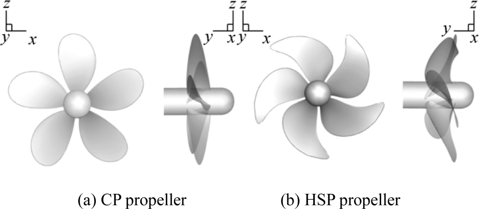
Seiun Maru CP and HSP are five-bladed marine propellers designed in Japan. CP has a modified MAU section with a fixed radial pitch, while HSP has a modified SRI-B section characterized by a variable radial pitch. The propellers have diameters of 3.6 m and are widely used as benchmarks for flow simulations (Carlton 2012). Propellers are modeled using a Fortran code based on the geometric characteristics, and the spatial point coordinates for different cross sections are provided (Belhenniche et al. 2016). The main particulars of the two propellers are summarized in Table 1, and propeller geometries are shown in Figure 1.
Table 1 Geometric properties of highly skewed and conventional Seiun Maru propellersProperties HSP CP D (m) 3.60 3.60 Ae/A0 0.70 0.65 P/D0.7R 0.944 0.950 Z 5 5 Boss ratio 0.1972 0.1972 Skew angle (%) 45 10.5 Section Modified SRI-B Modified MAU Material Ni-Al-Br Ni-Al-Br Direction of rotation Right-hand Right-hand 3 Computational Details for Open-Water and Behind-Ship-Hull Conditions
Details of the numerical implementation used are given in this section. Two different cases are examined in this study: open-water and behind-ship-hull cases. The numerical setup was kept similar in both cases as much as possible. Deviations were present where necessary and explained in this section.
3.1 Governing Equations
To obtain the velocity and pressure fields, the conservation form of the unsteady Navier-Stokes equation along with momentum equations was numerically solved. The equations are described as follows:
$$ \frac{\partial \rho }{\partial t}+\frac{\partial \left(\rho {u}_i\right)}{\partial {x}_i}=0 $$ (1) $$ \frac{\partial \left(\rho {u}_i\right)}{\partial t}+\frac{\partial \left(\rho {u}_i{u}_j\right)}{\partial {x}_j}=-\frac{\partial p}{\partial x}+\frac{\partial }{\partial {x}_j}\left(\mu \frac{\partial {u}_i}{\partial {x}_j}-\overline{\rho {u}_i^{\prime }{u}_j^{\prime }}\right) $$ (2) where ui is the averaged velocity, p is the averaged pressure, ρ is the density, μ is the dynamic viscosity, and $ -\overline{\rho {u}_i^{\prime }{u}_j^{\prime }} $ is the Reynolds stress. A well-known fact is that the open-water characteristics can be described by the following no dimensional equations:
$$ {K}_T=\frac{T}{\rho {n}^2{D}^4} $$ (3) $$ {K}_Q=\frac{Q}{\rho {n}^2{D}^5} $$ (4) $$ {\eta}_0=\frac{K_T}{K_Q}.\frac{J}{2\pi} $$ (5) The Reynolds number of the propeller based on chord length at 0.7R is defined as:
$$ \mathit{{Re}}=\frac{C_{0.7R}\sqrt{V^2+\left(0.7\pi nD\right)}}{\nu}\kern0.5em $$ (6) where n denotes the rotational speed; D refers to the propeller diameter; T is the thrust; Q is the torque; ρ and ν are the density and the kinematic viscosity of water, respectively; and C0.7R is the chord length at 0.7R. For noise prediction, FW-H method is a solution developed from the Lighthill equation (Lighthill 1954; Ffowcs Williams and Hawkings 1969) and is derived from continuity and momentum equations. This equation is a good approach to extract sound pressure levels to the far field. Lighthill's acoustic analogy is given as follows:
$$ \frac{\partial^2\rho }{\partial {t}^2}+{c}_0^2{\nabla}^2\rho =\frac{\partial^2{T}_{ij}}{\partial {x}_i{x}_j} $$ (7) where
$$ {T}_{ij}=\overline{\rho {u}_i^{\prime }{u}_j^{\prime }}+{\delta}_{ij}\left(p-\rho {c}_0^2\right)+{\tau}_{ij} $$ (8) where Tij is the Lighthill stress sensor, the first term in the right side represents the Reynolds stresses, the second term is due to changes in pressure and density, and the last term is due to the shear stress tensor. The FW-H equation is represented as follows:
$$ \frac{\partial^2{p}^{\prime }}{\partial {t}^2}-{c}_0^2\frac{\partial^2{p}^{\prime }}{\partial {x}_i^2}=\frac{\partial^2{T}_{ij}}{\partial {x}_i{x}_j}-\frac{\partial }{\partial {x}_i}\left[{P}_{ij}\delta (f)\frac{\partial f}{\partial {x}_j}\right]+\frac{\partial }{\partial t}\left[{\rho}_0{u}_i\delta (f)\frac{\partial f}{\partial {x}_j}\right] $$ (9) where p′ is the sound pressure defined by p′ = p − p0 and c0 denotes the sound speed in the far field. δ(f) is the Dirac delta function, and f is the function of the moving boundary f(x, t) = 0. Pij is the compressive stress tensor defined as follows:
$$ {P}_{ij}=p{\delta}_{ij}-\mu \left(\frac{\partial {u}_i}{\partial {x}_j}+\frac{\partial {u}_j}{\partial {x}_i}-\frac{2}{3}\frac{u_k}{x_k}{\delta}_{ij}\right) $$ (10) The first term on the right-hand side of Eq. (9) is the quadruple source, which was neglected in this study because the speed of sound is faster than the propeller rotational speed. This term is considered only for high Mach numbers. Brentner and Farassat proposed a correlation (Farassat 2007), which is a solution to the FW-H equation in the time domain. In their formulation, the pressure field is defined as follows:
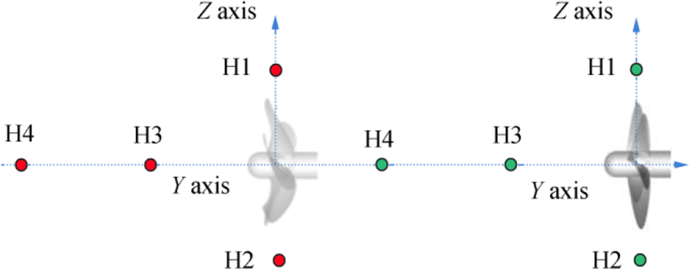
$$ {P}^{\prime}\left(\boldsymbol{x},t\right)={P}_T^{\prime}\left(\boldsymbol{x},t\right)+{P}_L^{\prime}\left(\boldsymbol{x},t\right) $$ (11) where $ {P}_T^{\prime } $ denotes the acoustic pressure level due to thickness and $ {P}_L^{\prime } $ describes the acoustic pressure level due to loading. The two acoustic pressures, $ {P}_T^{\prime } $ and $ {P}_L^{\prime } $, correspond to the monopole and the dipole sources, respectively, e.g., blade thickness rotation and unsteady sheet cavity volume fluctuations are modeled as monopole sources, and blade surface pressure fluctuations are modeled as a dipole source term (Seol et al. 2005). Four receivers were located in the wake and propeller disk. Figure 2 represents the hydrophone arrangements around CP and HSP Seiun Maru marine propellers.
Hydrophones were positioned on the radial and rotation axis, with two hydrophones for each axis. Table 2 shows the geometrical arrangement of all hydrophones used in this study.
Table 2 Coordinates of hydrophones given in Figure 2Hydrophones X (m) Y (m) Z (m) θ (°) H1 0 0 1.5R 90 H2 0 0 − 1.5R 90 H3 0 − 2R 0 0 H4 0 − 4R 0 0 3.2 Grid Sensitivity Study
Determining the correct pressure distributions on the propeller surfaces is vital to obtain reliable hydroacoustic results.
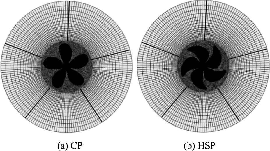
Therefore, at this point of the study, we present a grid sensitivity study that was carried out before continuing on to numerically solve propeller noise. To control the mesh size, the computational domain was divided into 18 blocks. Three inner blocks with one inner block surrounded the propeller, and these inner blocks were covered by 15 outer blocks. A hybrid mesh was adopted for the computational domain; tetrahedral elements were applied for the inner blocks, while hexahedral elements were used for the outer blocks. The blades and the shaft were meshed using constant tetra cells. As stated before, grid structure is important in resolving the pressure distribution along the propeller; therefore, we abstained from using an automatic meshing software. We used a relatively old software called Gambit to manually discretize the fluid domain with a meticulous grid structure.
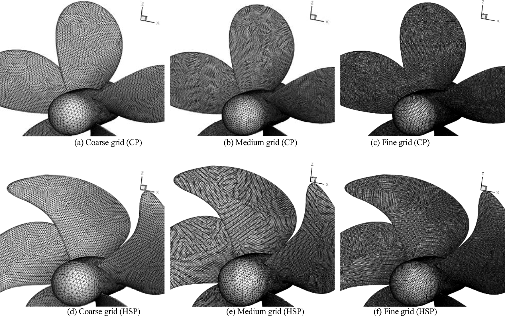
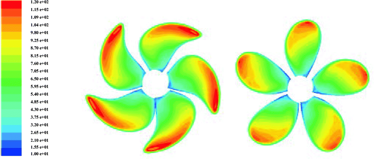
To determine the effect of grid systems on the results, the grid sensitivity was studied by using a grid refinement ratio $ {r}_G=\sqrt{2} $ (Stern et al. 1999). Three grids were used and referred to as coarse, medium, and fine grids. Illustrations of the grids generated on the propeller are shown in Figure 3. ANSYS TGrid 14.0 was used to solve the turbulent boundary layer on solid surfaces. The propeller domain generated in Gambit was exported into TGrid, where four layers of prismatic cells were attached to the blade surface. For the medium mesh, the first cell height of the solid surface was approximately 0.001065D, and the average y+ on the propellers was within 10–120 (see Figure 4), which was suitable for the turbulence model implemented in this study. Propulsion parameters KT, 10KQ, and η0 were evaluated to assess the suitability of the grid structure. Details of the grid system used for the sensitivity study are shown in Tables 3 and 4.
Table 3 Grid systems used in sensitivity analyses for steady simulations of CPBlocks Cells Coarse grid Medium grid Fine grid Inner block 1 (Aft of prop.) Tetra 33 755 75 801 181 460 Inner block 2 (Fwd of prop.) Tetra 32 260 72 134 189 323 Inner block 3 (Propeller bloc) Tetra Blade mesh size, 0.008D Blade mesh size, 0.006D Blade mesh size, 0.004D Shaft mesh size, 0.016D Shaft mesh size, 0.011D Shaft mesh size, 0.008D Max. size in block, 0.029D
303 522Max. size in block, 0.021D
653 468Max. size in block, 0.015D
1 460 323Propeller prism layer number Wedge 04 04 04 Propeller prism layer cells Wedge 147 820 299 236 590 428 Exterior blocks 4–8 Hexa 09 × 18 × 18 = 14 580 12 × 25 × 25 = 37 500 18 × 36 × 36 = 116 640 Exterior blocks 9–13 Hexa 09 × 18 × 18 = 14 580 12 × 25 × 25 = 37 500 18 × 36 × 36 = 116 640 Exterior blocks 14–18 Hexa 09 × 18 × 32 = 25 920 12 × 25 × 45 = 67 500 18 × 36 × 64 = 207 360 Total cells – 572 437 1 173 139 2 862 274 Table 4 Grid systems used in sensitivity analyses for steady simulations of HSPBlocks Cells Coarse grid Medium grid Fine grid Inner block 1 (Aft of prop.) Tetra 33 755 75 801 181 460 Inner block 2 (Fwd of prop.) Tetra 32 260 72 134 189 323 Inner block 3 (Propeller bloc) Tetra Blade mesh size, 0.008D Blade mesh size, 0.006D Blade mesh size, 0.004D Shaft mesh size, 0.016D Shaft mesh size, 0.011D Shaft mesh size, 0.008D Max. size in block, 0.029D
323 253Max. size in block, 0.021D
688 770Max. size in block, 0.015D
1 532 127Propeller prism layer number Wedge 04 04 04 Propeller prism layer cells Wedge 161 552 328 184 637 020 Exterior blocks 4–8 Hexa 09 × 18 × 18 = 14 580 12 × 25 × 25 = 37 500 18 × 36 × 36 = 116 640 Exterior blocks 9–13 Hexa 09 × 18 × 18 = 14 580 12 × 25 × 25 = 37 500 18 × 36 × 36 = 116 640 Exterior blocks 14–18 Hexa 09 × 18 × 32 = 25 920 12 × 25 × 45 = 67 500 18 × 36 × 64 = 207 360 Total cells – 605 900 1 307 389 2 980 570 Figure 5 shows a layout of the fine grid at a cross section of the full domain. Although the block covering the propeller (block 3) might have a different number of elements for the HSP and CP cases, the number of elements in the rest of the domain was strictly the same.
3.3 Boundary and Working Conditions
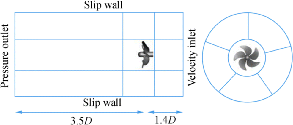
For the boundary conditions of the steady simulation:
– Velocity inlet was located at 1.4D characterized by a uniform flow depending on the advance coefficient J.
– Pressure outlet was located at 3.5D.
– Slip condition was set for the side wall at 1.4D (Belhenniche et al. 2012).
– No slip condition was imposed for the shaft and the propeller (see Figure 6).
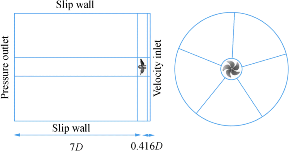
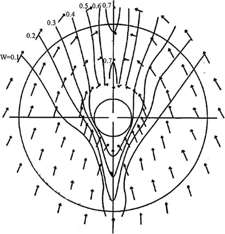
For transient simulations, the same conditions were adopted with the only exception at the inlet, where the axial velocities calculated from a non-uniform ship wake were given as input (Belhenniche et al. 2016).
To maintain the non-uniform wake in the propeller plane, the inlet must not be too distant, which would lead to a dissipation of the non-uniform wake and becoming uniform (Ji et al. 2012a, b). The inlet, outlet, and side wall were located at 0.416D, 7D, and 3D, respectively, from the propeller plane, as shown in Figure 7. The distribution of the nominal ship wake is illustrated in Figure 8.
To match the conditions in the experiments, open-water simulations were performed for CP and HSP Seiun Maru propellers at a model scale with a diameter of 0.4 m and a revolution of 217.8 r/min. Computational results were compared with the experimental data presented in Ukon et al. (1989, 1990, 1991). Simulations were performed to cover the entire advance coefficient range J, i.e., 0.1 ≤J≤1.0. However, for the case of propellers operating behind the ship hull, full-scale propellers were used with rotation rates of 91.3 and 90.7 r/min for CP and HSP respectively, both working at an advance coefficient of J = 0.85. Computational results were also compared with those of the SQCM method (Nakatake et al. 2002). Hydroacoustic calculations were performed behind a non-uniform ship wake (behind-ship-hull condition) (Özden et al., 2016; Yao and Zhang 2018; Ji et al. 2012a, b) for both HSP and CP Seiun Maru marine propellers under the abovementioned conditions for different hydrophone positions by using a transient solver. Although the hull can be included in simulations, such as in (Long et al. 2019), we abstained from modeling the ship due to high-computer memory requirements. Reference pressure was set as 1 μPa, while the velocity of sound in the undisturbed medium was 1500 m/s.
3.4 Details of Numerical Implementation
Farkas et al. (2018) stated that "numerical results are very similar, regardless of turbulence model" for an open-water propeller. Therefore, k − ε turbulence model (Launder and Spalding 1972) was used for both steady (uniform flow) and transient (non-uniform ship wake) simulations to close Reynolds' stress term $ -\overline{\rho {u}_i^{\prime }{u}_j^{\prime }} $. It is a widely used turbulence model in solving the flow around marine propellers; see, for instance, Ji et al. (2012a, b). Numerical equations were solved using ANSYS Fluent 14.0 based on the finite volume method. For the steady simulation, a second-order scheme was selected for pressure discretization, and second-order upwind was chosen to discretize momentum, turbulent kinetic energy, and specific dissipation rate. A moving reference frame approach was used, and velocity-pressure coupling was made by the Semi-Implicit Method for Pressure-Lined Equation algorithm.
For transient simulations, the standard scheme was chosen for pressure discretization, and the QUICK scheme was selected for the momentum equation. A first-order upwind scheme was used for the discretization of turbulent kinetic energy and specific dissipation rate. Velocity and pressure coupling was made by the Pressure-Implicit with Splitting of Operators algorithm. Sliding mesh technique was applied for the transient simulation, which was accomplished by directly rotating the internal domain, including the propeller. Time step size was set to 1.83756 × 10⁻³ s for HSP and 1.82548 × 10⁻³ s for CP, which correspond to rotation angles of 1 degree for each.
The number of iterations between each physical time step was set to 80 to achieve better convergence. For the acoustic simulation, with the use of the time-dependent flow field data as an input, simulation results were used to solve the FW-H equation to extract the acoustic pressure and the sound pressure level for four hydrophones. Time step was again set to correspond to a rotation angle of 1 degree for propellers operating in non-uniform ship wake simulation. In this case, 10 inner iterations between each physical time step were set. All residuals for simulations involved in both cases were below 10−6.
The computer used in this study was an ordinary computer with Intel Core i7-3632QM with 2.20 GHz CPU. The open-water case contained about 3 million elements, and simulations at each advance coefficient took around 12 h. All simulations were performed by assuming a steady state as hypothesis. For the non-uniform ship wake condition, the number of elements was slightly higher. The only simulation carried out for this case was transient. A total of 3.5 million elements with a time step size of about ∆t ≈ 1.8 × 10⁻³ took about 30 days to finish.
4 Hydrodynamic Results
The numerical results of open-water and behind-ship-hull conditions for Seiun Maru CP and HSP are given in this section. Section "Performance Prediction in Open-Water" presents the hydrodynamic performances of the propeller in the open-water case. However, the presence of a ship hull in front of a working propeller changes propulsion characteristics considerably (Kinaci and Gokce 2015). Section "Performance Prediction in Non-uniform Ship Wake" presents the calculated hydrodynamic performances behind a non-uniform ship wake. These two sections are given to provide validations and a solid background for hydroacoustic simulations. Section 4.3 presents the numerical hydroacoustic simulation results.
4.1 Performance Prediction in Open-Water
Numerical simulations were carried out for a wide range of advance coefficients and similar to experiments. Inlet velocity was adjusted to vary the advance coefficient. Results of the grid sensitivity study at J = 0.8 are illustrated in Table 5. Error percentages in this table were calculated by:
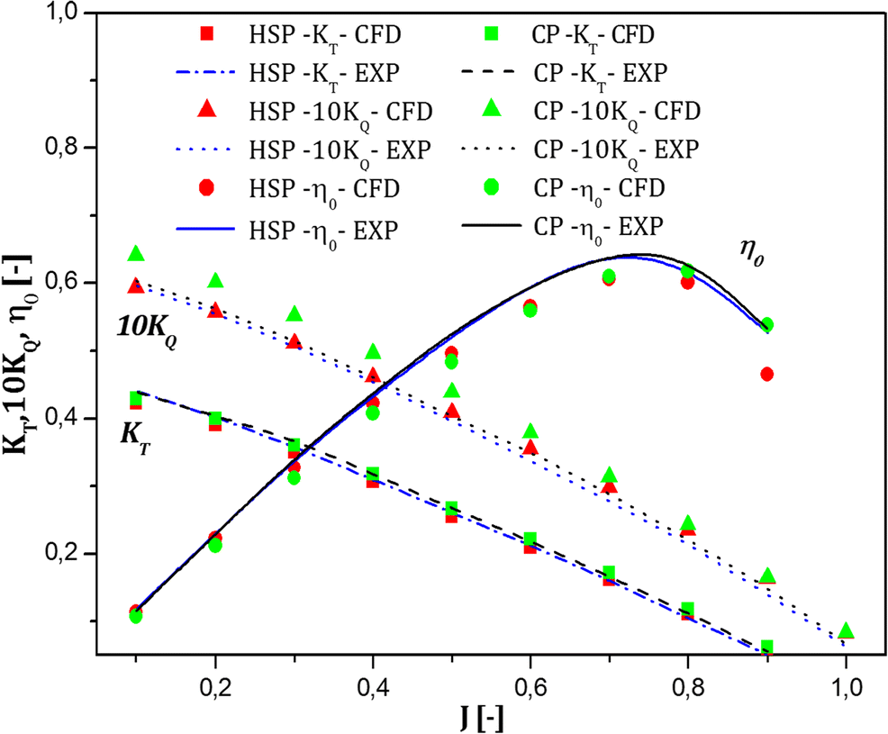
$$ \varepsilon =\frac{\left|{K}_{T,\exp }-{K}_{T,\mathrm{CFD}}\right|}{K_{T,\exp }}\times 100\% $$ (12) Table 5 Grid sensitivity study for CP and HSP at J = 0.8Grid sensitivity CP HSP KT Error|ε|(%) KT Error|ε|(%) Coarse grid 0.120 7.14 0.113 6.60 Medium grid 0.119 6.25 0.112 5.66 Fine grid 0.118 5.35 0.111 4.50 Experiment 0.112 – 0.106 – Table 5 shows that the discrepancy between experimental and numerical solutions decreases with an increasing number of elements. Thus, fin grid system was adopted to present the numerical results. The open-water characteristics for CP and HSP are shown in Figure 9. Results show a comparison of the computed thrust and torque curves predicted against experimental values (Ukon et al. 1989, 1990, 1991), and the computed results fit the experimental ones well.
Similar to experiments, numerical results also suggest that the CP generates higher thrust and torque. Open-water propeller efficiencies seem to be similar both experimentally and numerically. Numerical prediction of torque was somehow higher than that of experiments, which led to lower predicted open-water efficiency; see Eq. (5).
4.2 Performance Prediction in Non-uniform Ship Wake
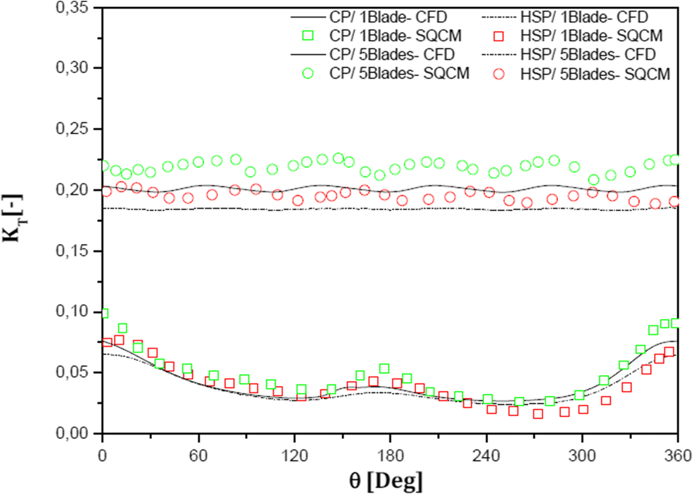
Figure 10 shows the thrust coefficient distributions generated by one-bladed and five-bladed propellers. Qualitatively, thrust predictions are in accordance with the calculations of Nakatake et al. (2002), who used a surface panel method (SQCM). This figure shows that the CFD results are slightly lower than those of SQCM. This result is due to the viscous approach implemented in this study unlike the potential-based SQCM method where the flow is assumed to be inviscid. Another notable detail in this figure is that CP generates higher thrust than HSP. This result is also in accordance with the open-water case, in which CP thrusts were higher than HSP thrusts in the advance coefficient range covered in this study (see Figure 9).
An interesting point that can be observed from this figure is the interaction between propeller blades. Mean thrust coefficients during one revolution of CP and HSP for the one-blade and five-blade cases are given in Table 6. The CP generates a higher thrust than the HSP, as also stated previously. This finding is also valid for the one-blade case.
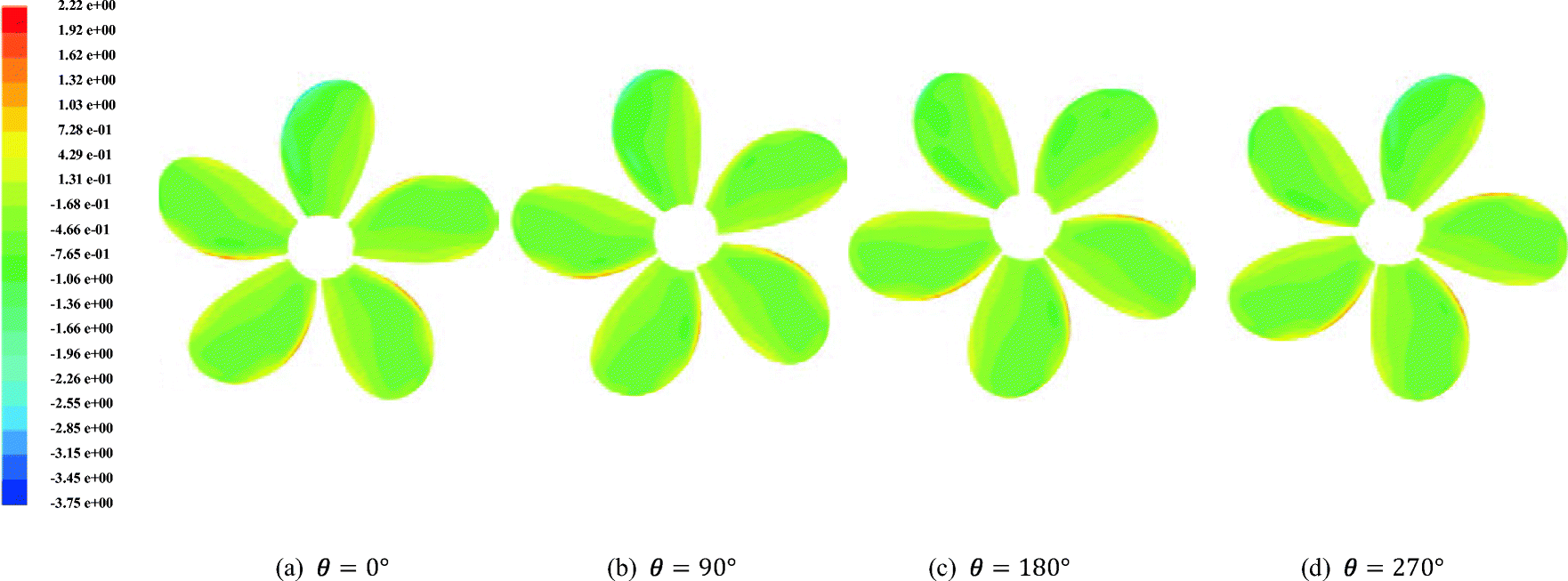
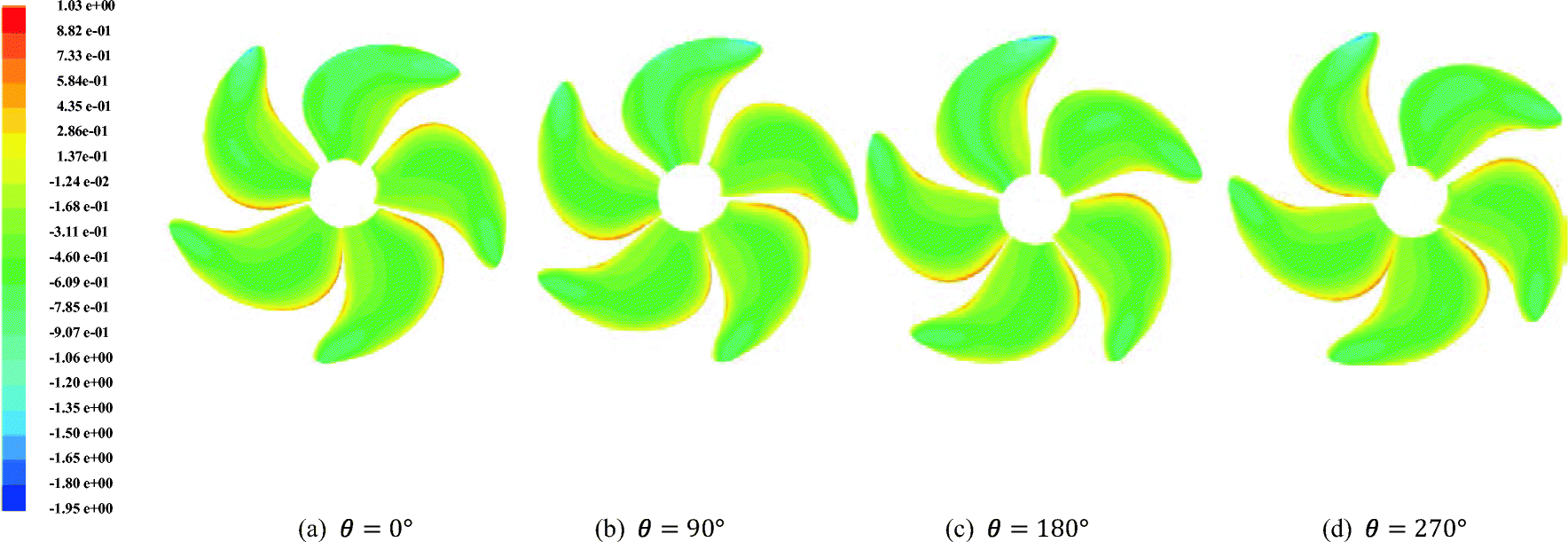
Table 6 Average thrust for both propellers in the behind-ship-hull conditionNo. CP HSP 1 blade 0.0414 0.0375 5 blades 0.2011 0.1844 Figures 11 and 12 show pressure coefficient distributions over CP and HSP on the suction side, respectively, for different angle positions. This figure notes the differences in pressure at each angle. This difference is due evidently to the propeller being subjected to a non-uniform flow. A detail that should be noted from this figure is that the regions of blades closer to the hull have lower pressures, as indicated by blue colors at the upper part of the propeller. In this region, the flow becomes stuck in between the propeller and the bottom side of the hull. The region behaves like a jet, and the velocity increases, thereby decreasing the pressure, which is a sign of the possible occurrence of cavitation.
5 Hydroacoustic Results
After satisfactory agreement with experiments was obtained for the hydrodynamic properties of both Seiun Maru propellers, the noise levels generated by these propellers were predicted numerically. However, hydroacoustic experiments for propellers are difficult to conduct. Full-scale experiments are prone to background noise, and the repeatability of these experiments is nearly impossible to achieve because controlling all environmental conditions to the same levels is difficult. Experiments carried out in towing tanks suffer from refractions from the side walls of the tank (Ianniello et al. 2013). In addition, eliminating noise generated by the towing tank itself is a difficult task. Given all these reasons, the numerical approach is generally validated by hydrodynamic data in many studies. Some examples that adopt such an approach are Ianniello et al. (2013), Bagheri et al. (2015), and; Yao and Zhang (2018). Our numerical approach was validated both in open-water and non-uniform flow conditions previously. However, an additional validation study was carried out and presented in this section to validate our hydroacoustic results before we present our findings.
5.1 Hydroacoustic Validation: the DTMB 4119 Case
A validation test of the FW-H equation was carried out for the well-known DTMB 4119 marine propeller. Numerical results presented in other studies (Bagheri et al. 2015; Sezen et al. 2016) were used for comparison. The same mesh structure and numerical implementation was used here.
First, the open-water characteristics were calculated and compared with experiments and panel method (Brizzolara et al. 2008) at a revolution rate of 600 r/min. Then, the time-dependent pressure data were used as input for the FW-H formulation to predict the far-field noise levels. The propeller had a revolution rate of 960 r/min and was operating at an advance coefficient of J = 0.54. Figure 13 shows the open-water performances of DTMB 4119 and the noise levels calculated at 10R and θ=90°. A comparison with available results (Bagheri et al. 2015; Sezen et al. 2016; Brizzolara et al. 2008) shows good agreement for both hydrodynamic and hydroacoustic calculations. Although these are all numerical results and further validation with experiments is required, the general trends of the curves agree, and the BPF is observable in all of them.
5.2 Noise Predictions in the Behind-Ship-Hull Condition: Non-uniform Ship Wake Case
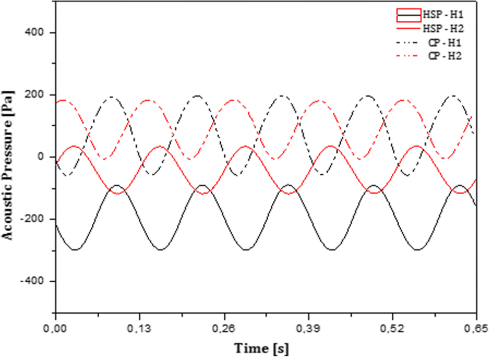
Pressure fluctuations in time for the last rotation are presented in Figure 14 for hydrophones 1 and 2. Five peaks in pressure record correspond to five blades of CP and HSP. The difference in acoustic pressures between hydrophones 1 and 2 for both propellers is due to the non-uniform ship wake, where the lack of axial velocity is more pronounced at the blade top position than at the lowest position. Acoustic pressures for hydrophones 3 and 4 were not presented because pressure peaks could not be identified at these locations. Indeed, pressure signals in time were complex in this chaotic region. The URANS approach may be unable to accurately predict the hydroacoustic signal in the wake generated by the propeller because the method cannot capture almost turbulent structures (Wu et al. 2018). Even so, peaks at noise spectra were identifiable; see Figure 15.
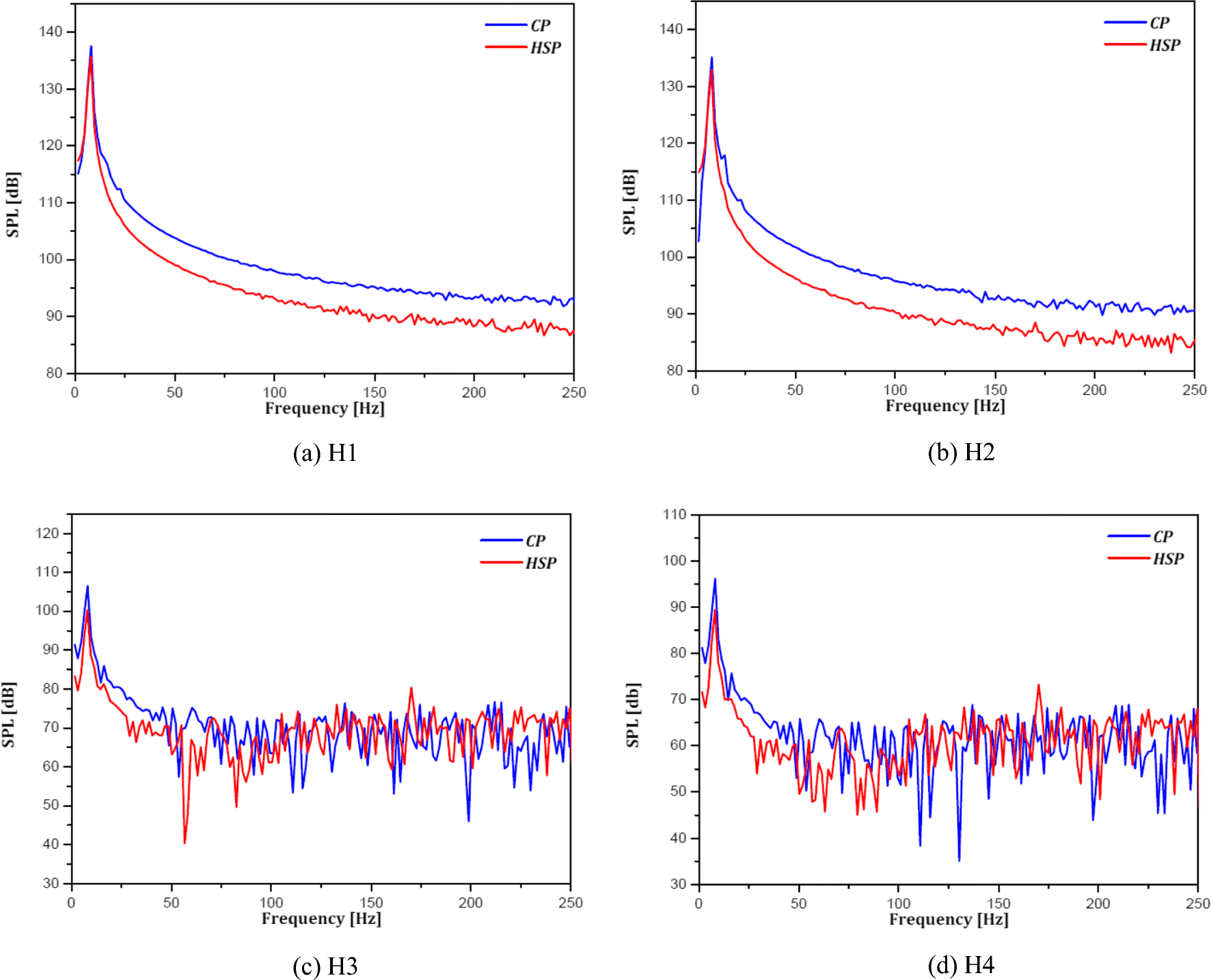
Figure 15 shows the sound pressure levels for hydrophones 1–4. In these figures, frequency f is given by:
$$ f=\frac{1}{2\cdotp \Delta t} $$ (13) However, only frequencies up to 250 Hz are given in these figures. A different time step size selection process was proposed recently by Sezen and Kinaci (2019), thereby allowing higher harmonics of noise to be captured by setting smaller time steps. However, considering only the peaks at the first BPF, accordance may exist in the first harmonics of both propellers. BPF is given by:
$$ \mathrm{BPF}=n\cdotp Z $$ (14) Fundamental (first) harmonics should be 7.602 Hz for CP and 7.558 Hz for HSP. First harmonics were captured clearly at all hydrophone locations, while subharmonics and higher harmonics could hardly be observed. A possible reason for this condition might be the implementation of RANS as a turbulence model, in which many aspects of the flow are averaged. Other harmonics might have been lost during this process, but stronger evidence is needed, and further study must be carried out before pointing out the exact source of this deficiency in results.
Results show that highest values of the sound pressure levels are largely intense in the low-frequency range (0–50), while they are low at higher frequencies. The sound pressure level reaches its maximum at the first order of BPF (1st BPF) and gradually decreases at higher harmonics. Overall sound pressure levels (OASPLs) were also calculated at these hydrophone locations by the following:
$$ \mathrm{OASPL}=10\log \left({\int}_0^{f_{\mathrm{max}}}{10}^{\frac{\mathrm{SPL}(f)}{10}}\cdotp \mathrm{d}f\right) $$ (15) Table 7 shows the OASPLs for both CP and HSP at different hydrophone positions. This table indicates that HSP exhibits slightly less noise than CP. Nevertheless, a minor reduction in the hydrodynamic efficiency of HSP compared with CP should also be noted. An important detail to mention is that these results are for the noncavitating case. However, the hydroacoustic performances will probably be more amplified in the presence of cavitation.
Table 7 Propulsion parameters and sound pressure levels for both propellers at J = 0.85Items CP HSP KT 0.201 0.184 KQ 0.033 0.031 ηB 0.824 0.803 H1 (dB) 141 139 H2 (dB) 138 136 H3 (dB) 110 104 H4 (dB) 100 94 6 Conclusions
Numerical investigations were performed to predict and compare the noise characteristics of CP and HSP Seiun Maru marine propellers behind non-uniform ship wake. Numerical calculations were carried out under noncavitating conditions. RANS equations were coupled with the FW-H equation. The numerical approach was first validated from the hydrodynamic aspect for both open-water and behind-ship-hull conditions. Experimental noise data are not available for the tested marine propellers in the literature. Therefore, the hydroacoustic numerical approach was validated by the DTMB 4119 propeller before moving any further with the study. After satisfactory agreement with other studies in the literature was observed, numerical comparisons of hydrodynamic and hydroacoustic performances of CP and HSP marine propellers were carried out. The following are some highlights and conclusions drawn from this study:
1) The predicted open-water characteristics of CP and HSP agree well with the experimental measurements for a wide range of advance coefficients.
2) The calculated thrust coefficient of both propellers behind a non-uniform ship wake during propeller revolution shows good agreement with the SQCM.
3) Periodic features of the thrust coefficient were observed under non-uniform ship wake by using the unsteady solver. Findings show that CP generates higher thrust.
4) The RANS method with the k − ε turbulence model indicates that it is an effective tool to predict the hydrodynamic performances for both steady (open-water) and transient (non-uniform ship wake) conditions. It also generated satisfactory results for hydroacoustic calculations.
5) Noise levels were presented for several hydrophones. The positions of SPL peaks are in good agreement with the theoretical values of BPF. The highest values of SPL are concentrated in the low-frequency range and decrease at high frequencies.
6) OASPLs were calculated both for CP and HSP behind a non-uniform ship wake. HSP generates less noise than CP, but it is also less hydrodynamically efficient. Thus, a trade-off exists between the hydrodynamic and hydroacoustic performances of a marine propeller, and an optimization study is required prior to the selection of the propulsion system of the ship.
Nomenclature
Acknowledgments: Authors wish to acknowledge the Naval AeroHydrodynamic Laboratory of the Marine Engineering Department for its continuous support. We would also like to thank the Aeronautics and Propulsion Systems Laboratory for its invaluable help.D Propeller diameter P/D0.7R: Pitch ratio at 0.7R C0.7R Chord length at 0.7R Tmax0.7R Maximum blade section thickness at 0.7R Fmax0.7R Maximum blade section camber at 0.7R Ae/A0: Expanded area ratio J Advance coefficient Z Blade number y+ Non-dimensional normal distance from the wall ui Average velocity p Average pressure KT Thrust coefficient KQ Torque coefficient ρ Density of water μ Dynamic viscosity T Propeller thrust Q Propeller torque n Propeller rotational speed η0 Propeller open-water efficiency ηB Propeller behind-ship-hull efficiency Re Reynolds number t Time step f Frequency Cp Pressure coefficient rG Grid refinement $u_i$ Fluctuating velocity component ${\rm{ - }}\overline {\rho u_i^{'}u_j^{'}} $ Reynolds stress tensor p′ Sound pressure c0 Sound speed Pij Compressive stress tensor P′(x, t): Acoustic pressure $P_T^{'}\left( {\mathit{\boldsymbol{x}},t} \right)$ Acoustic pressure resulting from thickness $P_L^{'}\left( {\mathit{\boldsymbol{x}},t} \right)$ Acoustic pressure resulting from loading Tij Lighthill stress tensor SPL Sound pressure level OASPL Overall sound pressure level BPF Blade passage frequency -
Table 1 Geometric properties of highly skewed and conventional Seiun Maru propellers
Properties HSP CP D (m) 3.60 3.60 Ae/A0 0.70 0.65 P/D0.7R 0.944 0.950 Z 5 5 Boss ratio 0.1972 0.1972 Skew angle (%) 45 10.5 Section Modified SRI-B Modified MAU Material Ni-Al-Br Ni-Al-Br Direction of rotation Right-hand Right-hand Table 2 Coordinates of hydrophones given in Figure 2
Hydrophones X (m) Y (m) Z (m) θ (°) H1 0 0 1.5R 90 H2 0 0 − 1.5R 90 H3 0 − 2R 0 0 H4 0 − 4R 0 0 Table 3 Grid systems used in sensitivity analyses for steady simulations of CP
Blocks Cells Coarse grid Medium grid Fine grid Inner block 1 (Aft of prop.) Tetra 33 755 75 801 181 460 Inner block 2 (Fwd of prop.) Tetra 32 260 72 134 189 323 Inner block 3 (Propeller bloc) Tetra Blade mesh size, 0.008D Blade mesh size, 0.006D Blade mesh size, 0.004D Shaft mesh size, 0.016D Shaft mesh size, 0.011D Shaft mesh size, 0.008D Max. size in block, 0.029D
303 522Max. size in block, 0.021D
653 468Max. size in block, 0.015D
1 460 323Propeller prism layer number Wedge 04 04 04 Propeller prism layer cells Wedge 147 820 299 236 590 428 Exterior blocks 4–8 Hexa 09 × 18 × 18 = 14 580 12 × 25 × 25 = 37 500 18 × 36 × 36 = 116 640 Exterior blocks 9–13 Hexa 09 × 18 × 18 = 14 580 12 × 25 × 25 = 37 500 18 × 36 × 36 = 116 640 Exterior blocks 14–18 Hexa 09 × 18 × 32 = 25 920 12 × 25 × 45 = 67 500 18 × 36 × 64 = 207 360 Total cells – 572 437 1 173 139 2 862 274 Table 4 Grid systems used in sensitivity analyses for steady simulations of HSP
Blocks Cells Coarse grid Medium grid Fine grid Inner block 1 (Aft of prop.) Tetra 33 755 75 801 181 460 Inner block 2 (Fwd of prop.) Tetra 32 260 72 134 189 323 Inner block 3 (Propeller bloc) Tetra Blade mesh size, 0.008D Blade mesh size, 0.006D Blade mesh size, 0.004D Shaft mesh size, 0.016D Shaft mesh size, 0.011D Shaft mesh size, 0.008D Max. size in block, 0.029D
323 253Max. size in block, 0.021D
688 770Max. size in block, 0.015D
1 532 127Propeller prism layer number Wedge 04 04 04 Propeller prism layer cells Wedge 161 552 328 184 637 020 Exterior blocks 4–8 Hexa 09 × 18 × 18 = 14 580 12 × 25 × 25 = 37 500 18 × 36 × 36 = 116 640 Exterior blocks 9–13 Hexa 09 × 18 × 18 = 14 580 12 × 25 × 25 = 37 500 18 × 36 × 36 = 116 640 Exterior blocks 14–18 Hexa 09 × 18 × 32 = 25 920 12 × 25 × 45 = 67 500 18 × 36 × 64 = 207 360 Total cells – 605 900 1 307 389 2 980 570 Table 5 Grid sensitivity study for CP and HSP at J = 0.8
Grid sensitivity CP HSP KT Error|ε|(%) KT Error|ε|(%) Coarse grid 0.120 7.14 0.113 6.60 Medium grid 0.119 6.25 0.112 5.66 Fine grid 0.118 5.35 0.111 4.50 Experiment 0.112 – 0.106 – Table 6 Average thrust for both propellers in the behind-ship-hull condition
No. CP HSP 1 blade 0.0414 0.0375 5 blades 0.2011 0.1844 Table 7 Propulsion parameters and sound pressure levels for both propellers at J = 0.85
Items CP HSP KT 0.201 0.184 KQ 0.033 0.031 ηB 0.824 0.803 H1 (dB) 141 139 H2 (dB) 138 136 H3 (dB) 110 104 H4 (dB) 100 94 D Propeller diameter P/D0.7R: Pitch ratio at 0.7R C0.7R Chord length at 0.7R Tmax0.7R Maximum blade section thickness at 0.7R Fmax0.7R Maximum blade section camber at 0.7R Ae/A0: Expanded area ratio J Advance coefficient Z Blade number y+ Non-dimensional normal distance from the wall ui Average velocity p Average pressure KT Thrust coefficient KQ Torque coefficient ρ Density of water μ Dynamic viscosity T Propeller thrust Q Propeller torque n Propeller rotational speed η0 Propeller open-water efficiency ηB Propeller behind-ship-hull efficiency Re Reynolds number t Time step f Frequency Cp Pressure coefficient rG Grid refinement $u_i$ Fluctuating velocity component ${\rm{ - }}\overline {\rho u_i^{'}u_j^{'}} $ Reynolds stress tensor p′ Sound pressure c0 Sound speed Pij Compressive stress tensor P′(x, t): Acoustic pressure $P_T^{'}\left( {\mathit{\boldsymbol{x}},t} \right)$ Acoustic pressure resulting from thickness $P_L^{'}\left( {\mathit{\boldsymbol{x}},t} \right)$ Acoustic pressure resulting from loading Tij Lighthill stress tensor SPL Sound pressure level OASPL Overall sound pressure level BPF Blade passage frequency -
Aktas B, Turkmen S, Sampson, Shi W, Fitzsimmons P, Korkut E, Atlar M (2015) Underwater radiated noise investigations of cavitating propellers using medium size cavitation tunnel tests and full-scale trials. Fourth international symposium on marine propulsors (SMP), Austin, USA Bagheri M, Saeed Seif M, Mehdigholi H, Yaakob O (2015) Analysis of noise behaviour for marine propellers under cavitating and non-cavitating conditions. Ships Offshore Struct 12(1): 1–8. https://doi.org/10.1080/17445302.2015.1099224 Belhenniche SE, Aounallah M, Imine O, Çelik F (2012) Application of CFD in analysis of steady and unsteady turbulent flow past a marine propeller. International Conference of Heat and Mass Transfer ICHMT, Palermo Belhenniche SE, Aounallah M, Imine O, Çelik F (2016) Effect of geometric configurations on hydrodynamic performance assessment of a marine propeller. Brodogradnja 67(4): 31–48. https://doi.org/10.21278/brod67403 Bertschneider H, Bosschers J, Choi GH, Ciappi E, Farabee T, Kawakita C, Tang D (2014) Specialist Committee on Hydrodynamic Noise. Technical report, ITTC Brizzolara S, Villa D, Gaggero S (2008) A systematic comparison between RANS and panel methods for propeller analysis. Proceedings of the 8th International Conference on Hydrodynamics, Nantes Brooker A, Humphrey VF (2014) Measurement of radiated underwater noise from a small research vessel in shallow water. A. Yücel Odabasi Colloquium Series, Istanbul, pp 47–55 Carlton J (2012) Marine propeller and propulsion, 3rd ed. Elsevier Ltd. Dekeling R (2014) Underwater soundscapes. J Ocean Technol 9(1): 2–10 Ekinci S, Çelik F, Guner M (2010) A practical noise prediction method for cavitating marine propellers. Brodogradnja 61(4): 359–366 Farassat F (2007) Derivation of formulations 1 and 1A of Farassat. NASA Langley Research Center, Aeroacoustic Branch Report Farkas A, Degiuli N, Martic I (2018) Assessment of hydrodynamic characteristics of a full-scale ship at different draughts. Ocean Eng 156: 135–152. https://doi.org/10.1016/j.oceaneng.2018.03.002 Ffowcs Williams JE, Hawkings DL (1969) Sound generation by turbulence and surfaces in arbitrary motion. Philos Trans R Soc Lond Ser A Math Phys Sci 264(1151): 321–342 Ghassemi H, Gorji M, Mohammadi J (2018) Effect of tip rake angle on the hydrodynamic characteristics and sound pressure level around the marine propeller. Ships Offshore Struct 13(7): 759–768. https://doi.org/10.1080/17445302.2018.1457207 Gokce MK, Kinaci OK, Alkan AD (2018) Self-propulsion estimations for a bulk carrier. Ships Offshore Struct 14(7): 656–663. https://doi.org/10.1080/17445302.2018.1544108 Ianniello S, Muscari R, Di Mascio A (2013) Ship underwater noise assessment by the acoustic analogy. part Ⅰ: nonlinear analysis of a marine propeller in uniform flow. J Mar Sci Technol 18: 547–570. https://doi.org/10.1007/s00773-013-0227-0 Jasak H, Vukcevic V, Gatin I, Lalovic I (2019) CFD validation and grid sensitivity studies of full-scale ship self propulsion. Int J Naval Archit Ocean Eng 11(1): 33–43. https://doi.org/10.1016/j.ijnaoe.2017.12.004 Ji B, Luo X, Peng X, Wu Y, Xu H (2012a) Numerical analysis of cavitation evolution and excited pressure fluctuation around a propeller in non-uniform wake. Int J Multiphase Flow 43: 13–21. https://doi.org/10.1016/j.ijmultiphaseflow.2012.02.006 Ji B, Luo X, Wu Y, Peng X, Xu H (2012b) Partially-averaged Navier–stokes method with modified k–ε model for cavitating flow around a marine propeller in a non-uniform wake. Int J Heat Mass Transf 55(23–24): 6582–6588. https://doi.org/10.1016/j.ijheatmasstransfer.2012.06.065 Kinaci OK, Gokce MK (2015) A computational hydrodynamic analysis of Duisburg test case with free surface and propeller. Brodogradnja 66(4): 23–38 Kinaci OK, Gokce MK, Alkan AD, Kukner A (2018) On self-propulsion assessment of marine vehicles. Brodogradnja 69(4): 29–51. https://doi.org/10.21278/brod69403 Launder BE, Spalding DB (1972) Mathematical models of turbulence. Academic Press Lighthill MJ (1954) On sound generated aerodynamically Ⅱ. Turbulence as a source of sound. Proc R Soc Lond Ser A Math Phys Sci 222(1148): 1–32 Long Y, Long X, Ji B, Huang H (2019) Numerical simulations of cavitating turbulent flow around a marine propeller behind the hull with analyses of the vorticity distribution and particle tracks. Ocean Eng 189: 106310. https://doi.org/10.1016/j.oceaneng.2019.106310 McKenna MF (2011) Blue whale response to underwater noise from commercial ships. PhD thesis, University of California, San Diego Mousavi B, Rahrovi A, Kheradmand A (2014) Numerical simulation of tonal and broadband hydrodynamic noises of non-cavitating underwater propeller. Polish Maritime Research 21(3): 46–53. https://doi.org/10.2478/pomr-2014-0029 Nakatake K, Ando J, Kataoka K, Yoshitake A (2002) A simple surface panel method SQCM for ship hydrodynamics. International Association for Boundary Element Methods (IABM) Özden MC, Gürkan A, Özden YA, Canyurt TG, Korkut E (2014) Underwater radiated noise prediction for a submarine propeller in different flow conditions. A. Yücel Odabaşı Colloquium Series, Istanbul Pan Y, Zhang H (2010) Numerical hydro-acoustic prediction of marine propeller noise. J Shanghai Jiaotong Univ (Science) 15(6): 707–712. https://doi.org/10.1007/s12204-010-1073-4 Seol H, Jung B, Suh J, Lee S (2002) Prediction of non-cavitating underwater propeller noise. J Sound Vib 257(1): 131–156. https://doi.org/10.1006/jsvi.5035 Seol H, Jung B, Suh J, Lee S (2005) Development of hybrid method for the prediction of underwater propeller noise. J Sound Vib 288(1–2): 345–360. https://doi.org/10.1016/j.jsv.2005.01.015 Sezen S, Kinaci OK (2019) Incompressible flow assumption in hydroacoustic predictions of marine propellers. Ocean Eng 186: 106138. https://doi.org/10.1016/j.oceaneng.2019.106138 Sezen S, Dogrul A, Bal S (2016) Investigation of marine propeller noise for steady and transient flow. The Second Global Conference on Innovation in Marine Technology and the Future of Maritime Transportation, Mugla, Turkey Stern F, Wilson RV, Coleman HW, Paterson EG (1999) Verification and validation of CFD simulations. Iowa Institute of Hydraulic Research, Technical Report, No. 407 Ukon Y, Kurobe Y, Kudo T (1989) Measurement of pressure distribution on a conventional and highly skewed propeller model under non-cavitating condition. J Soc Naval Archit Japan 165: 83–94 (in Japanese) Ukon Y, Kurobe Y, Kudo H, Kamiriisa H, Yuasa H, Kubo Y, Itadani Y (1990) Measurement of pressure distribution on a full-scale propeller – measurement on a conventional propeller. J Soc Naval Archit Japan 168: 65–75 (in Japanese) Ukon Y, Kudo T, Kurobe Y, Yuasa H, Kamiirisa H, Kubo H (1991) Measurement of pressure distribution on a full-scale propeller: measurement on a highly skewed propeller. J Soc Naval Archit Japan 170: 111–123 (in Japanese) Wu Q, Huang B, Wang G, Cao S, Zhu M (2018) Numerical modelling of unsteady cavitation and induced noise around a marine propeller. Ocean Eng 160: 143–155. https://doi.org/10.1016/j.oceaneng.2018.04.028 Yao HL, Zhang HX (2018) Prediction of ship effective wake field using a pure RANS-based methodology. Nav Eng J 130(2): 141–152

