2. Ministry of Education Key Laboratory of High Performance Ship Technology, Wuhan University of Technology, Wuhan 430063, China
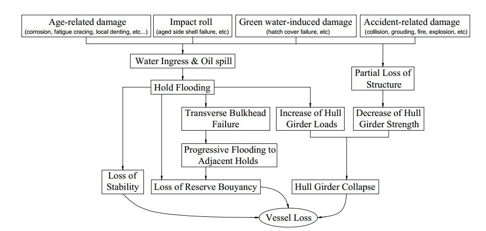
Ships face damages or collapse with various types of losses due to several factors that include ship type, cargo, routes, loads, and so on. The losses incurred are grouped into three categories, as shown in Fig. 1. The first type, loss of stability, is a result of hold flooding. When combined with transverse bulkhead failure, such an accident can lead to second type of loss, which is the loss of reserve buoyancy. The third one is hull girder collapse, which is due to age-related damages, such as corrosion, fatigue carking, local dents, and so on (Paik and Thayamballi, 1998a).
|
Figure 1 Loss scenarios involving different vessels (Paik and Thayamballi, 1998a) |
To ensure that oil tankers equal to or greater than 150 m in length satisfy the residual strength checking criteria According to the International Association Classification of Society -Common structural rules (IACS-CSR) requirements, these must be checked for the status of their seagoing condition (IACS, 2015). Following the requirements, the hull girder residual strength is represented by either hull girder ultimate strength (HGUS) or hull girder ultimate bending capacity. Alternative authors or inspectors in the field of naval architecture and ocean engineering have presented several methods to determine the HGUS. These proposed methods, which are classified into three categories, include direct methods, progressive collapse analysis, and ship accident investigation and model test (Qi and Cui, 2006). Direct methods include the use of empirical formulas, linear method, and analytical method. Meanwhile, progressive collapse analyses include the simplified method (or Smith's method), incremental-iterative method (IACS-CSR), idealized structural unit method, and non-linear finite element method.
When conducting investigations, conductors must consider several influent parameters that degrade the ultimate bending moment capacity of a ship hull girder. For example, initial imperfections, such as residual stresses and deformation, often result from manufacturing and erection actions, whereas operation activities cause other kinds of damages to ship structures, such as corrosion, cracks, and dents (Paik et al., 1998b; 2003a), among others.
In 2001, Sun and Bai investigated the reliability of the ship hull girder and ultimate strength of four different ships. To calculate the ultimate bending moment, they considered time-dependent corrosion and cracks as the main influencing factors and then combined these with the simplified method. Their results showed that the value of conditional reliability index of a double hull very large crude oil carrier (VLCC) in sagging condition is reduced by 80.62% when the ship age exceeds 10 years (Sun and Bai, 2001).
Hu and Cui (2014) as well as Zayed et al. (2013) studied the ultimate strength reliability of a hull girder under conditions of corrosion, fatigue, and constant maintenance of oil tankers Hu and Cui assessed the residual ultimate strength of stiffened panels, un-stiffened plates, ultimate hull girder bending moment, and the reliability of ship hull under conditions of corrosion, fatigue cracks, as well as constant inspection and repair criteria (Hu and Cui, 2004). Meanwhile, to analyze the lifetime reliability of ship structures, Zayed et al. used the inspection and repair actions and combined these with data on different levels of corrosion wastage (Zayed et al., 2013).
Paik et al. considered several types of damages, such as degradation (i.e., corrosion and fatigue cracks) and mechanical damage (i.e., local dent), to assess the effects of these factors on the ultimate strength performance and risk assessment of aged tankers / Floating Production Storage and Offloading (FPSOs). The selected ships were investigated in terms of time-dependent reliability or risk, ultimate strength reduction, damage tolerance design, rational repair and maintenance scheme, and so on (Paik et al., 2003a). In 2009, Paik and Kim applied progressive collapse analysis method, which employed data on net, gross, and 50% corrosion margin, to conduct a comparative study of different scantlings of the structure of a Suezmax class double hull oil tanker. They concluded that the levels of initial imperfections related to fabrication have significant influence on the ultimate strength of a ship hull girder. In this research field, CSR design technology is expected to be increasingly advantageous in terms of the ultimate strength design of tanker structures (Paik et al., 2009).
From 2012 to 2014, Kim et al. published a series of studies regarding the safety assessment and time-variant ultimate longitudinal strength of corroded oil tankers and other types of ship. Using the ALPS/HULL program based on Intelligent Supersize Finite Element Method, they calculated the HGUS under corrosion wastage (Paik et al., 2003b). These studies clearly evaluated the effect of corrosion wastage on the ship hull in terms of moment of inertia, section modulus, repair period requirements, and ultimate strength reduction of stiffened panels or hull girders (Kim et al., 2012; 2014a; 2014b).
Guedes Soares and his collaborators provided in-depth investigations on corroded ships in their publications. Their works concentrated on the reliability of aged ship hull under different factors, such as corrosion. In one study, Guedes Soares and Garbatov (1996) assessed the effect of thickness degradation due to repair policy, corrosion and corrosion rate, and allowable stresses on the reliability of maintained single hull tanker. In another study, different inspection intervals, corrosion rates, as well as allowable stresses and thicknesses were applied to the same problem (Guedes Soares and Garbatov, 1997). Past studies have also investigated the reliability of a maintained ship hull girder subjected to fatigue, different repair policies, corrosion, and maintenance actions (Guedes Soares and Garbatov, 1998), as well as corrosion, crack growth, different loading conditions, fatigue, and maintenance (Guedes Soares and Garbatov, 1999). In 2008, the reliability of a 25-year service single hull oil tanker was assessed. To analyze the reliability of the hull girder, that study employed the first-order reliability method featuring three assumptions of thickness (Parunov et al., 2008).
The abovementioned studies considered the effect of one fixed corrosion rate level on the ultimate hull girder bending moment capacity. In comparison, the aim of the present study is to assess the effect of corrosion wastage on a double hull VLCC. The probabilistic corrosion model that was applied had six different corrosion wastage levels. The checking criteria are then employed to assess the satisfaction of residual hull girder strength at each point of a ship's lifetime.
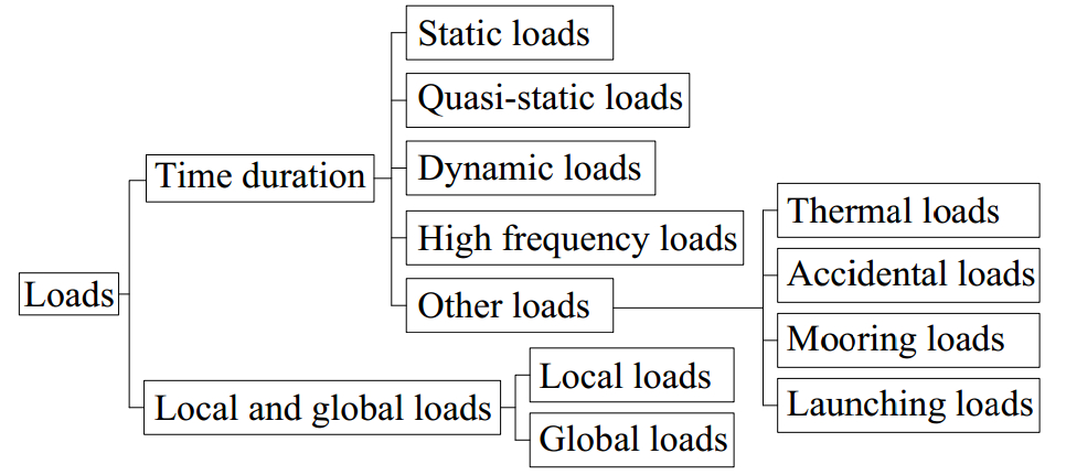
2 Ultimate strength of the hull girder 2.1 Ultimate limit state of oil tankersThe diagram of applied loads on ship hull is drawn in Fig. 2 (Bai, 2003). Hull girder loads can be classified into two main types: Dynamic Hull Girder Loads (DHGL) and Vertical Still Water Hull Girder Loads (VSWHGL). DHGL is divided into five categories, including horizontal wave bending moment, vertical wave bending moment, vertical wave shear force, wave torsional moment, and hull girder loads for dynamic loading cases. Meanwhile, VSWHGL includes vertical still water bending moment and vertical still water shear forces (IACS, 2015). The current study considers only the vertical bending moment, which is obtained and specified by the criteria expressed as
| $ {\mathit{\boldsymbol{\gamma }}_S}{M_{{\bf{SW - U}}}} + {\mathit{\boldsymbol{\gamma }}_W}{M_{{\bf{WV}}}} \le \frac{{{M_u}}}{{{\mathit{\boldsymbol{\gamma }}_R}}} $ | (1) |
|
Figure 2 Classification of loads |
where Mu is the vertical hull girder ultimate bending capacity, MSW-U is the permissible still water bending moment, MWV is the vertical wave bending moment, γS is the partial safety factor for the still water bending moment, γW is the partial safety factor for the vertical wave bending moment, and γR is the partial safety factor for the vertical hull girder ultimate bending capacity.
To ensure the safety of hull girder in seagoing condition, some limit states are considered, including serviceability, fatigue, accident, and ultimate limit states. Among these, ultimate limit state is considered in the present study. This limit state refers to the collapse of a structure resulting from a loss of structural capacity in terms of stiffness and strength, which may typically arise from the plastic collapse and buckling of the main structural components (ISSC, 2012).
2.2 Hull girder ultimate strength methodThe Ultimate Bending Moment Capacity (UBMC) is calculated by using the incremental-iterative method, which is established by IACS-CSR. This method, which considers the critical failure modes of all main longitudinal structural elements belonging to each transverse section, has some assumptions listed below.
● The ultimate strength is calculated based on the hull transverse sections between the two adjacent transverse webs.
● The hull girder transverse section remains plane during each curvature increment.
● The hull material displays an elasto-plastic behavior.
● The hull girder transverse section is categorized into a set of elements, which act independently from one another.
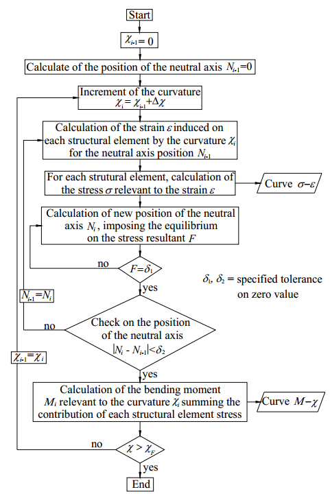
In determining UBMC, the following main steps are followed concurrently with a flow chart, which results in the M-χ curve shown in Fig. 3.
|
Figure 3 Flow chart of the procedure for the evaluation of the M-χ curve (IACS, 2015) |
● Step 1: Divide the transverse section of the hull into several stiffened plate elements.
● Step 2: Define the stress-strain relationships among all elements.
● Step 3: Initialize neutral axis and curvature χ1 for the first incremental step.
● Step 4: Calculate the corresponding stress σi and corresponding strain εi for each element.
● Step 5: Identify the neutral axis ZNA_cur at each incremental step.
● Step 6: Identify the corresponding moment through calculation.
● Step 7: Compare the moment in the current incremental step with that in the previous one. The process is terminated and the peak value is defined if the slope in the M-χ relationship is less than a negative fixed value. Otherwise, increase the curvature by the amount of Δχ and go to Step 4.
Following the aforementioned process, the UBMC (Mu) is identified as the peak point of the M-χ curve, which results from the bending moment components of all incremental steps expressed by
| $ {M_u} = \sum {{\mathit{\boldsymbol{\sigma }}_{ui}}{A_{i - n50}}\left({{Z_i} - {Z_{{\bf{NA\_cur}}}}} \right)} $ | (2) |
where σui is the stress of element, Ai is the net cross-sectional area of element, and Zi is the vertical distance from the baseline to the horizontal neutral axis of the element.
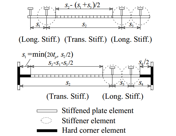
2.3 Ultimate strength of the structural componentsIn accordance with the guidelines of IACS-CSR, the transverse section is divided into three types of elements: hard corner element, stiffened plate element, and stiffener element, as shown in Fig. 4. In identifying the weakest inter-frame failure mode, all relevant failure modes for individual structural elements are considered. Table 1 presents the corresponding failure modes and stress-strain relationships.
|
Figure 4 Element definition (IACS, 2015) |
|
|
Table 1 Modes of failure of individual structural elements |
Various authors or groups of researchers have developed several corrosion models to predict the corrosion wear and corrosion process. These models are classified into two main categories. The first category covers all the models that do not include time of coating life in their assumptions. This means that the corrosion appears immediately once ships begin operation.
The second category includes all other remaining models. One major idea assumed by these corrosion models is that all coating protection systems remain effective during the coating life time; hence, no corrosion may occur throughout this period. After that, corrosion on the steel surface may either appear immediately or follow a transition time before emerging.
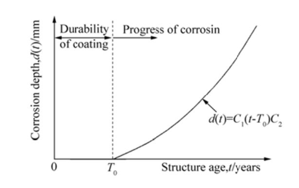
In 2003, Paik et al. proposed a probabilistic corrosion model that they developed based on statistical and measured data obtained from double hull tanker corrosion. Hence, we consider this model as the most suitable among other options in assessing the effects of corrosion on the HGUS of double hull tankers. As indicated in Fig. 5, the corrosion model is divided into two phases, one related to the coating life and another concerned with the progress of corrosion, but without transition duration. The corrosion rate r(t) and corrosion wear d(t) are defined respectively as (Paik et al., 2003a)
| $ r\left(t \right) = {C_1} $ | (3) |
| $ d\left(t \right) = {C_1}{\left({t - {T_0}} \right)^{{C_2}}} $ | (4) |
|
Figure 5 Corrosion model proposed by Paik et al. (2003b) |
where the annualized corrosion rate (C1) follows the Weibull distribution, and coefficient C2 is assumed to be 1.0.
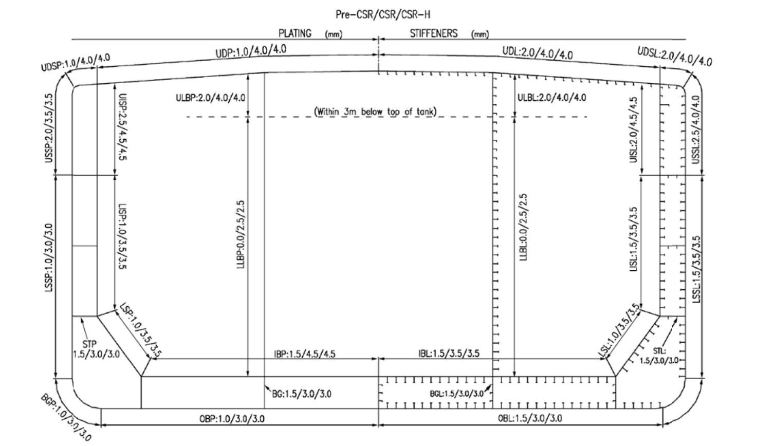
Coefficient C1 is defined for each part of the structural component, such as plating, stiffener flange, and stiffener web. The identified elements with the change of corrosion addition value and the mean value of C1 are indicated in Fig. 6 (Kim et al., 2014b) and Table 2 (Paik and Thayamballi, 2007), respectively.
|
Figure 6 Structural groups and corrosion addition value of a double hull tanker UDP -Upper deck plating, UDSP -Upper deck stringer plating, USSP -Upper side shell plating, LSSP -Lower side shell plating, BGP -Bilge plating, OBP -Outer bottom plating, IBP -Inner bottom plating, LSP -Lower sloping tank plating, LISP -Lower inner side plating, UISP -Upper inner side plating, STP -Side stringer plating, BG -Bottom girder plating, LLBP -Lower longitudinal bulkhead plating, ULBP -Upper longitudinal bulkhead plating, UDL -Upper deck longitudinal, UDSL -Upper deck stringer longitudinal, USSL -Upper side shell longitudinal, LSSL -Lower side shell longitudinal, OBL -Outer bottom longitudinal, IBL -Inner bottom longitudinal, LSL -Lower sloping tank longitudinal, LISL -Lower inner side longitudinal, UISL -Upper inner side longitudinal, STL -Side stringer longitudinal, BGL -Bottom girder longitudinal, LLBL -Lower longitudinal bulkhead longitudinal, and ULBL -Upper longitudinal bulkhead longitudinal |
|
|
Table 2 Annualized corrosion rates of structural group members |
The moment of inertia can be calculated using the equation (Hughes and Paik, 2010)
| $ {I_y} = \sum\limits_{j = 1}^n {\left({{a_j}z_j^2 + {i_j}} \right) - \left({\sum\limits_{j = 1}^n {{a_j}} } \right){g^2}} $ | (5) |
where aj is the cross-sectional area of the jth element, zj is the distance from the baseline of the ship to the neutral axis of jth element, ij is the moment of inertia of the jth element, n is the total number of elements included in the section modulus calculation, and g is the distance from the baseline of the ship to the neutral axis position.
The section modulus at deck (Zd) and bottom (Zb) are defined respectively using the equations (IACS, 2015)
| $ {Z_b} = \frac{{{I_y}}}{g}, \;\;\;\;{Z_d} = \frac{{{I_y}}}{{D - g}} $ | (6) |
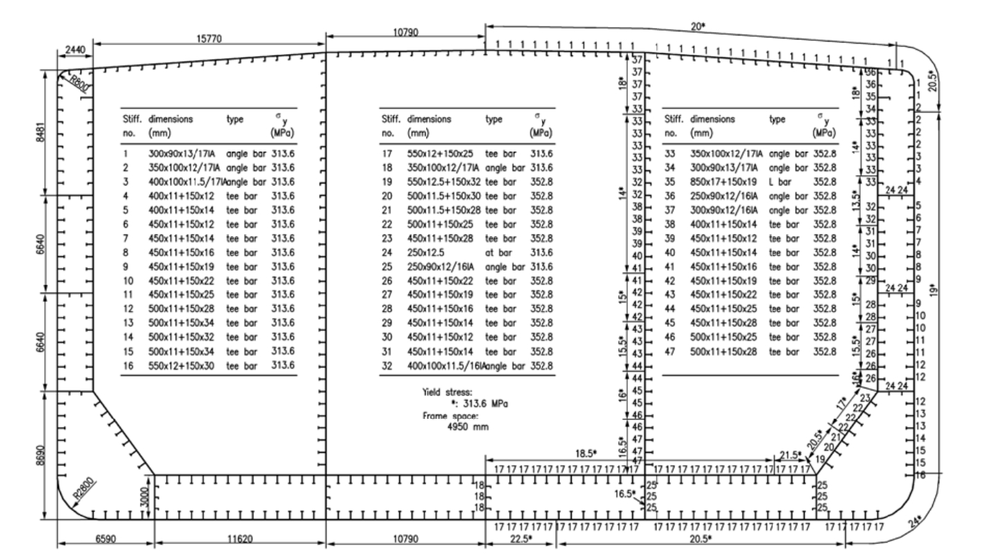
The applied ship in this paper, a 300000 DWT double hull VLCC, is one of the ships used in the benchmark study of the International Ship and Offshore Structures Congress (ISSC, 2012). The main principles are presented in Table 3, and the cross-sectional properties are shown in Table 4. Meanwhile, Fig. 7 illustrates the structural and material properties of the mid-ship section of the selected ship.
|
|
Table 3 Principal dimensions of double hull VLCC |
|
|
Table 4 Hull cross-sectional properties of double hull VLCC |
|
Figure 7 Mid-ship section of a double hull VLCC |
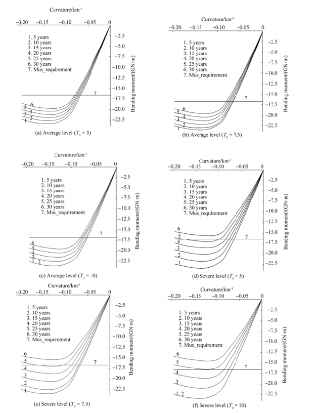
The effect of corrosion on the ship hull is determined in the case of sagging condition with two levels of corrosion wastage ("average" and "severe"). Three assumptions of coating life time (5, 7.5, and 10 years) for each level of corrosion wastage are adopted. The calculative results are obtained with relevant analyses.
Fig. 8 presents the change of vertical bending moment under six different levels of corrosion wastage: ship ages in the 5th, 10th, 15th, 20th, 25th, and 30th years, respectively. Moreover, in comparing the satisfaction of ultimate bending moment of the ship hull girder, the minimum bending moment capacity under the IACS-CSR requirement is also considered.
|
Figure 8 Vertical bending moments in sagging condition |
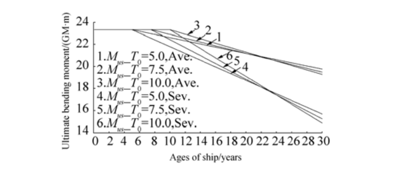
Fig. 9 shows the reduction of ultimate bending moment in six different cases. As can be seen, the degradation of Mus under severe corrosion is consistently higher than the counterpart. Throughout the 30-year period, the ultimate bending moment of ship hull girder in the case of average corrosion (T0=5) is reduced by almost 15%, whereas that for the case of severe corrosion (T0=10) is nearly 38%. Furthermore, in the case of average corrosion, the ultimate bending moment is consistently larger than the minimum bending moment capacity. Whereas, in the case of severe corrosion, the ultimate bending moment is smaller than the requirement when the coating life time is larger.
|
Figure 9 The change of ultimate bending moment in the sagging condition |
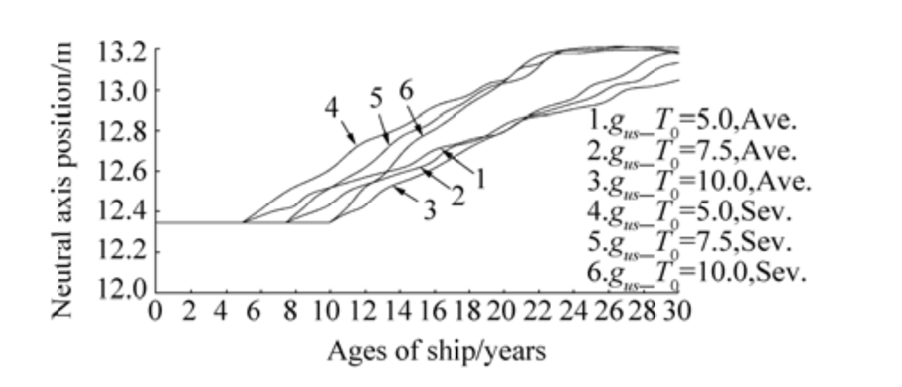
Fig. 10 shows the change of the neutral axis position at the ultimate limit state in sagging condition (gus). As can be seen, the decreasing thicknesses of the structural elements lead to the reduction of total sectional area arising from the neutral axis position. In the case of severe corrosion, the minimum and maximum change of the neutral axis position is obtained (T0=10) with 6.5% for the latter. Meanwhile, in the case of average corrosion, the minimum and maximum change of the neutral axis position is obtained (T0=5) with 5.3% for the former.
|
Figure 10 The change in neutral axis position at the ultimate limit state in the sagging condition |
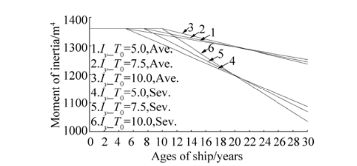
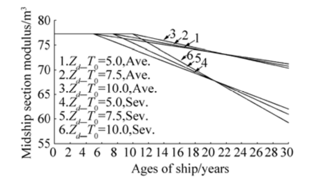
As the thickness of all the structural elements degrades, the moment of inertia decreases significantly, as shown in Fig. 11. The discrepancies between the moment of inertia of the hull section of the intact structure and the 30th year structure under the corrosion levels of "T0=5, Ave." and "T0=10, Sev." are nearly 8% and 24%, respectively. Such changes influence the section moduli at the deck and at the bottom with the similar patterns sown in Fig. 12 and Fig. 13.
|
Figure 11 The change of moment of inertia |
|
Figure 12 The change in section modulus at the deck |
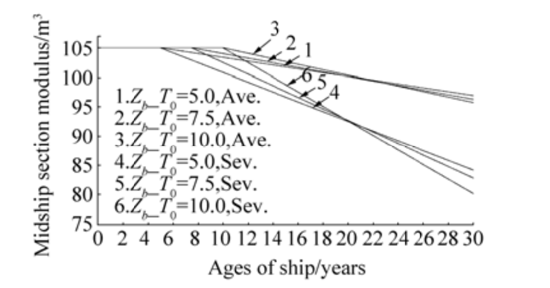
|
Figure 13 The change in section modulus at the bottom |
Table 5 presents the calculated results of the ultimate stress change of several representative elements. As can be seen, the Bottom Girder (BG) element shows the highest decline with about 46% in the case of "T0=10, Sev., " whereas the ultimate stress of bilge plating (BGP) element is not affected by the corrosion-induced thickness degradation. Clearly, the effect of severe corrosion on the ultimate stress capacity of the element is twice as much as that of average corrosion.
|
|
Table 5 Ultimate stress of elements |
We calculate the checking criteria satisfaction of the residual strength of a ship hull in sagging condition based on different ship ages, and the results are shown in Table 6. First, in the case of severe corrosion wastage, the residual strength requirement of a ship hull is unsatisfied in the cases of Ⅳ and Ⅵ at the age of 21 years, and this state will appear at the age of 22 years for the case of Ⅴ. In comparison, the strengths of ship hulls in the cases of Ⅰ, Ⅱ, and Ⅲ still satisfy the criteria throughout the assumed period.
|
|
Table 6 Checking criteria satisfaction |
The ultimate longitudinal strength under different levels of corrosion wastage of a double hull VLCC is investigated using the incremental-iterative method. On the basis of our investigations, several conclusions can be drawn, as listed below.
1) The UBMC of a hull girder is affected in varying degrees by the levels of corrosion wastage. Nevertheless, the overall degree of change increases along with the increase of corrosion level. The actual value of ultimate bending strength can be determined easily, and such information can be used to evaluate the residual strength of other similar double hull VLCCs.
2) The change of vertical moment of inertia leads to the change in the section moduli at the deck and at the bottom. When the thicknesses of the elements decrease, the values of these parameters also decrease. The discrepancy between them mainly depend on the corrosion rate (C1).
3) For the sagging condition, the greatest extent of degradation resulting from the ultimate stress of elements occurred in the bottom girder, inner side plating, and the stiffener elements. These have a significant impact on ship structure design, because the designers must now consider these locations in calculating and selecting the dimensions and profiles of various elements.
4) The point of dissatisfaction of ship hull girder strength, as shown in Table 6, must also be duly considered. Such an investigation is essential in setting inspection intervals as well as the repair and maintenance schedules of a ship.
However, this study did not consider the initial imperfections, such as production-related deformations, residual stresses, and cracks. In addition, presenting the stress behaviors of separated elements or different zones of a ship's cross-section. Hence, the numerical method should be employed and corrosion wastage, combined with the abovementioned factors, should also be considered in future works in this field.
Bai Y, 2003. Marine structural design. Elsevier Ltd, Oxford, UK. http://www.sciencedirect.com/science/book/9780080439211
( 0) 0)
|
Guedes Soares C, Garbatov Y. Reliability of maintained ship hulls subjected to corrosion[J]. Journal of Ship Research, 1996, 40(3): 235-243. ( 0) 0)
|
Guedes Soares C, Garbatov Y. Reliability assessment of maintained ship hulls with correlated corroded elements[J]. Marine Structures, 1997, 10(8): 629-653. DOI:10.1016/S0951-8339(98)00004-5 ( 0) 0)
|
Guedes Soares C, Garbatov Y. Reliability of maintained ship hull girders subjected to corrosion and fatigue[J]. Structural Safety, 1998, 20(3): 201-219. DOI:10.1016/S0167-4730(98)00005-8 ( 0) 0)
|
Guedes Soares C, Garbatov Y. Reliability of maintained ship hulls subjected to corrosion and fatigue under combined loading[J]. Journal of Constructional Steel Research, 1999, 52(1): 93-115. DOI:10.1016/S0143-974X(99)00016-4 ( 0) 0)
|
Hu Y, Cui WC, Pedersen PT. Maintained ship hull girder ultimate strength reliability considering corrosion and fatigue[J]. Marine Structures, 2004, 17(2004): 91-123. DOI:10.1016/j.marstruc.2004.06.001 ( 0) 0)
|
Hughes OF, Paik JK, 2010. Ship structural analysis and design. The Society of Naval Architects and Marine Engineers, Jersey City. https://repository.tudelft.nl/view/MMP/uuid:1cde0113-3071-4e9c-b4da-e69bc84e9cac/
( 0) 0)
|
IACS, 2015. Common structural rules for bulk carriers and oil tankers. International Association of Classification Societies, London, UK.
( 0) 0)
|
ISSC, 2012. Report of specialist committee Ⅲ. 1 ultimate strength. Proceedings of the 18th International Ship and Offshore Structures Congress, 1, 1-107 Rostock, Germany.
( 0) 0)
|
Kim DK, Park DK, Park DH, Kim HB, Kim BJ, Seo JK, Paik JK. Effect of corrosion on the ultimate strength of double hull oil tankers -Part Ⅱ:hull girders[J]. Structural Engineering and Mechanics, 2012, 42(4): 531-549. DOI:10.12989/sem.2012.42.4.531 ( 0) 0)
|
Kim DK, Kim HB, Zhang XM, Li CG, Paik JK. Ultimate strength performance of tankers associated with industry corrosion addition practices[J]. International Journal of Naval Architecture and Ocean Engineering, 2014a, 6(3): 507-528. DOI:10.2478/ijnaoe-2013-0196 ( 0) 0)
|
Kim DK, Liew MS, Youssef SAM, Mohd MH, Kim HB, Paik JK. Time-dependent ultimate strength performance of corroded FPSOs[J]. Arabian Journal for Science and Engineering, 2014b, 39(11): 7673-7690. DOI:10.1007/s13369-014-1364-4 ( 0) 0)
|
Paik JK, Thayamballi AK, 1998a. The strength and reliability of bulk carrier structures subject to age and accidental flooding. Transactions of the Society of Naval Architects and Marine Engineers, New Jersey, 106, 1-40.
( 0) 0)
|
Paik JK, Kim SK, Lee SK. Probabilistic corrosion rate estimation model for longitudinal strength members of bulk carriers[J]. Ocean Engineering, 1998b, 25(10): 837-860. DOI:10.1016/S0029-8018(97)10009-9 ( 0) 0)
|
Paik JK, Wang G, Thayamballi AK, Lee JM, Park YI, 2003a. Time-dependent risk assessment of aging ships accounting for general pit corrosion, fatigue cracking and local dent damage. 2003 SNAME annual meeting, World Maritime Technology Conference, San Francisco, USA.
( 0) 0)
|
Paik JK, Lee JM, Hwang JS, Park YI, 2003b. A time-dependent corrosion wastage model for the structures of single and double hull tankers and FSOs and FPSOs. Transaction of the Society of Naval Architects and Marine Engineers, New Jersey, 40(3), 201-217. http://www.ingentaconnect.com/content/sname/mt/2003/00000040/00000003/art00006
( 0) 0)
|
Paik JK, Thayamballi AK. Ship-shaped offshore installations[M]. New York: Cambridge University Press, 2007.
( 0) 0)
|
Paik JK, Kim DK, Kim MS. Ultimate strength performance of Suezmax tanker structures:Pre-CSR versus CSR designs[J]. International Journal of Maritime Engineering, 2009, 151(Part A2): 39-58. ( 0) 0)
|
Parunov J, Mage P, Guedes Soares C, 2008. Hull-girder reliability of an aged oil tanker. OMAE 2008: Proceedings of the 27th International Conference on Offshore Mechanics and Arctic Engineering, Estoril, Portugal, 207-215. DOI: 10.1115/OMAE2008-57183
( 0) 0)
|
Qi E, Cui W. Analytical method for ultimate strength calculations of intact and damaged ship hulls[J]. Ships and Offshore Structures, 2006, 1(2): 153-163. DOI:10.1533/saos.2006.0121 ( 0) 0)
|
Sun HH, Bai Y, 2001. Ultimate strength and reliability assessment for the ship hull girders used in ISSC-2000 benchmark study. Proceedings of the 8th International Symposium on Practical Design of Ships and Other Floating Structures, Shanghai, China, 2, 1005-1012. http://trid.trb.org/view/716275
( 0) 0)
|
Zayed A, Garbatov Y, Guedes Soares C. Reliability of ship hulls subjected to corrosion and maintenance[J]. Structural Safety, 2013, 43(2013): 1-11. DOI:10.1016/j.strusafe.2013.01.001 ( 0) 0)
|
 2017, Vol. 16


