2. Science and Technology on Underwater Vehicle Laboratory, Harbin Engineering University, Harbin 150001, China;
3. School of Marine Science and Technology, Newcastle University, NE1 7RU, UK
Generally, the propeller works aft in waves. The traditional ship self-propulsion test-ship power prediction method does not consider the hydrodynamic performance of the propeller under wave conditions unless coefficient correction is performed later. ITTC summarized four methods to calculate the increase of ship power in waves: direct powering method, torque rotational speed method, thrust rotational speed method, and resistance equal to thrust method (Arribas, 2007). However, all four methods have some assumptions, such as the increasing rate of ship power is constant, the thrust and torque of the propeller are proportional to the wave height quadratic, etc. These assumptions cannot reflect the actual condition of the ship in the waves; hence, none of the above methods can provide an accurate calculation of the ship's resistance increase in ballast condition. Therefore, it is necessary to investigate the hydrodynamic performance of the propeller under wave conditions (Ding, et al. 1998; Bu, et al. 2005; Kuang, et al. 2006; Liang, et al. 2006; Cheng, et al. 2007).
In the theoretical research, Natio and Nakamura (1979) assumed that the inflow velocity, thrust, and torque fluctuated sinusoidally. Then, they calculated the fluctuation thrust of the propeller under wave conditions with open-water characteristics curves. Fallinsen et al. (1981) considered the influence of the free surface on propeller hydrodynamics. They supposed the frequency of the propeller heave in waves is much smaller than the frequency of rotation. So, each time step of propeller heave motion can be considered as a steady problem. Then, the thrust coefficients were calculated at each time step of a propeller cycle, and their average value was considered as the mean thrust coefficient of the propeller under wave conditions. Tao et al.(1984, 1991) calculated the open-water propeller hydrodynamic performance in-regular waves by using 3D Green function method in which the propeller was replaced by sink disk. The calculation result were in accordance with tests. In addition, the effects of the immersion of propeller axis on the propeller performance are also calculated. Cao et al. (1988), attempted to get the open-water propeller characteristics, which are necessary for analyzing self-propulsion in wave, they performed the open-water tests with varying depth of propeller shaft. Then a simple quasi-steady calculation method is applied to predict the open-water characteristics of propeller in waves. The calculated values show good agreement with the results of model tests. Wang et al. (1989) proposed a quasi-steady lifting surface method for the prediction of characteristics of a propeller immersed near the water surface without air ventilation. The vortex lattice method was applied. The propeller loading and blade thickness were denoted respectively by discrete line vortex and source elements which were placed on the camber surface. The unknown strengths of vortex elements were determined by satisfying the no-penetration condition on the camber surface, the linearized free surface condition and the Kutta condition at trailing edges. Tao et al. (1999) used the Green function in potential flow theory to calculate the thrust decrease. They simplified the rotating propeller as a propeller with countless blades, and the velocity potential consists of the steady and unsteady components, with the unsteady components being the variable parameter in the waves. The source-sink distribution method was used to calculate the changing thrust. Yu (2008) analysed the hydrodynamic performance of propeller in wave. He divided the program into heaving due to the wave interspersed with diffraction of the waves. The heaving process was simulated by combining the technique of dynamic mesh and sliding mesh. Lee et al. (2010) used an overset grid approach to simulate the propeller performance under wave conditions. Califano and Steen et al. (2011) numerically simulated the phenomenon of ventilation on a fully submerged propeller, and found that the tip vortex plays an important role in ventilation of the conventional propellers, which is the object of the present study. Yari and Ghassemi (2016) used the boundary element method to numerically simulate the surface-piercing propeller in unsteady open-water conditions, and predicted the propeller's performance, unsteady ventilation pattern, and cross-flow effect on partially submerged propellers.
From an experimental research aspect, Lee, et al. (1983) researched the depth change and open-water characteristics relationship of propeller. They also studied the performance of a propeller under racing conditions. The propeller load fluctuations in waves are discussed together with blade stress and hull pressure fluctuations in waves. Jia, et al. (1990) continued the open-water tests with different conditions. They investigated the scaling problem of the ventilated propellers immersed near the free surface and studied the scaling theory, proposed the methods of judging the state of partial ventilation or super ventilation. And also developed the approximate formulate for predicting the performance of ventilated propeller. Paik, et al. (2005) performed the experiments in a circulating water channel to investigate the effects of a free surface on the wake behind a rotating propeller by using the particle image velocimetry technique. They found the free surface affect the axial velocity component and vortex structure behind the propeller. Guo, et al. (2012) conducted the experiment of a certain propeller under the same regular waves and different depths of propeller shaft. They studied the influence of depths of propeller shaft on thrust coefficient, torque coefficient and efficiency in calm water. The ventilation, runaway phenomenon of the propeller and the unsteady performance of the propeller in waves were also analyzed.
This paper performed a preliminary study and analysis on the influence of waves on the hydrodynamic performance of the propeller by experimental and numerical simulation methods.
2 Geometry and numerical methodsThe experiment is performed in the Ship Model Towing Tank Lab in Harbin Engineering University, China.
The propeller section is investigated separately in this experiment. The main geometrical parameters of the propeller are shown in Table 1. The propeller rotational speed, n is 1 200 r/min. The propeller advance coefficient is controlled between J = 0.1-0.7 by changing the inflow velocity. Table 2 shows the location parameters of the open-water tank in this experiment, and the definitions of these parameters are shown in Fig. 1. Table 3 shows the regular wave parameters used in this experiment (two-parameter ITTC spectrum), where Aw is the amplitude. HW is the wave height. λ is the wave length. And T is the wave period. The wave direction is opposite to the driving direction of the towing carriage.
|
|
Table 1 Main geometrical parameters of propeller |
|
|
Table 2 Main experimental parameters |

|
Figure 1 Schematic diagram of the open water tank |
|
|
Table 3 Wave parameters |
It is difficult to perform a direct simulation of the turbulence around complex engineering structures. Instead, time averaged methods (e.g. Reynolds averaging technique) are usually applied to simplify the instantaneous Navier-Stokes equations. The numerical simulations performed in the present work are based on the Reynolds-Averaged Navier-Stokes equations (Chakraborty and Cant, 2015).
| $ \rho \frac{{\partial {u_i}}}{{\partial {x_i}}} = 0 $ | (1) |
| $ \begin{array}{l} \frac{{\partial {u_i}}}{{\partial t}} + \rho \frac{\partial }{{\partial {x_j}}}({u_i}{u_j}) = - \frac{{\partial p}}{{\partial {x_i}}} + \\ \rho \frac{\partial }{{\partial {x_j}}}\left[ {\nu \left({\frac{{\partial {u_i}}}{{\partial {x_j}}} + \frac{{\partial {u_j}}}{{\partial {x_i}}}} \right)} \right] - \frac{\partial }{{\partial {x_j}}}(- \rho \overline {{u_i}'{u_j}'}) \end{array} $ | (2) |
where ui and uj(i, j=1, 2, 3) are the time averaged velocity components; xi and xj(i, j=1, 2, 3) are the coordinates in longitudinal, transverse, and vertical directions respectively; ρ is the fluid density; p is the time averaged pressure, ν is the water kinetic viscosity, and
The Shear Stress Transport (SST)k-ω model is used for turbulence modeling, which employs the solution of transport equations for k and ω:
| $ \frac{\partial }{{\partial t}}\left({\rho k} \right) + \frac{\partial }{{\partial xi}}\left({\rho kui} \right) = \frac{\partial }{{\partial xj}}\left({\Gamma_k\frac{{\partial k}}{{\partial xj}}} \right) + G_k - Y_k $ | (3) |
| $ \frac{\partial }{{\partial t}}\left({\rho \omega } \right) + \frac{\partial }{{\partial xi}}\left({\rho \omega ui} \right) = \frac{\partial }{{\partial xj}}\left({\Gamma_\omega \frac{{\partial \omega }}{{\partial xj}}} \right) + G_\omega - Y_\omega + D_\omega $ | (4) |
where G represents the generation of turbulent kinetic energy, k, or specific dissipation rate, ω, Y represents the dissipation of k or ω, D represents the cross-diffusion term, and Γ represents the effective diffusivity of k or ω. Further details regarding these equations are available in Aupoix (2015).
The turbulent viscosity for the k-ω SST model is evaluated using:
| $ {\mu _T} = \rho a\frac{k}{{\max \left({a\omega, {F_2}S} \right)}} $ | (5) |
with coefficients α = 5/9, and F2 = tanh(Φ2), and
| $ \Phi = \max \left[ {2\frac{{\sqrt k }}{{0.09\omega y}}, \frac{{500\mu }}{{\rho {y^2}\omega }}} \right] $ | (6) |
where y is the distance from the nearest wall.
2.3 Capture of free surfaceThe VOF method is used for simulating the free surface in this paper. The VOF transport equation is formulated as follows:
| $ \frac{{\partial \alpha }}{{\partial t}} + \nabla \cdot [(U - {U_g})\alpha ] + \nabla \cdot [{U_r}(1 - \alpha)] = 0 $ | (7) |
where α represents the volume of the fraction, the relative proportion of the two-phase fluid; α is used to distinguish the fluid of two phases. Furthermore U represents the velocity field while Ug represents the velocity of the mesh points. When α = 0, the fluid is air. When α = 1, the fluid is water. When α is between 0 and 1, this area is an interface of air and water.
2.4 Wave governing equationsFirst-Order VOF Waves and Fifth-Order VOF Waves are provided in STAR CCM+, and the former is employed in the present paper. For the First-Order VOF waves, the equation for horizontal velocity is:
| $ {V_h} = a{\pmb{\omega}} \cos ({\pmb{K}} \cdot x - {\pmb{\omega}} t){{\rm e}^{Kz}} $ | (8) |
The equation for vertical velocity is
| $ {V_v} = a{\pmb{\omega}} \sin ({\pmb{K}} \cdot x - {\pmb{\omega}} t){{\bf{e}}^{Kz}} $ | (9) |
The equation for surface elevation is
| $ {A_w} = a\cos ({\pmb{K}} \cdot x - {\pmb{\omega}} t) $ | (10) |
The wave period T is defined as:
| $ T = \frac{{2{\rm{\pi }}}}{{\omega '}} $ | (11) |
The wave length is defined as:
| $ \lambda = \frac{{2{\rm{\pi }}}}{K} $ | (12) |
where a is the wave amplitude; ω' is the frequency; K is the wave vector; K is the magnitude of the wave vector; and z is the vertical distance from the mean water level.
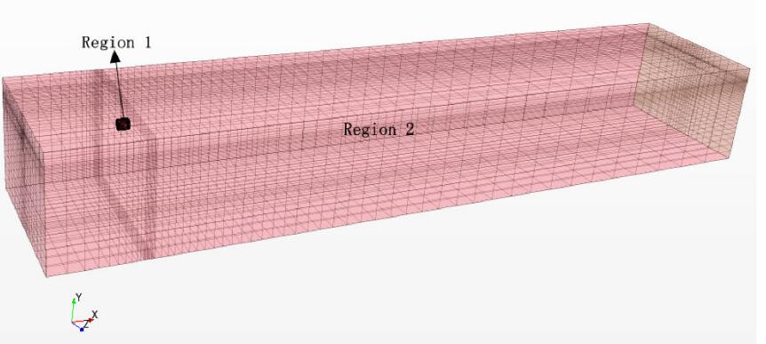
2.5 Problem configurationForm Fig. 2, the computational domain is a cuboid shape. It is divided into two regions, Region1 which is the column which surrounds the propeller and hub, and Region 2, which is the control region of other parts. The mesh for Region 1 is refined and coarser mesh is applied in Region 2. The global computational domain length is L = 27.5 m, which is five times the wave length LW while the depth and width are D = 5 m and B = 5 m respectively. During the simulations, Region1 rotates with the propeller blades.

|
Figure 2 Grid of the whole flow field |
The polyhedral mesh is employed in Region1 as shown in Fig. 3. And this mesh has highly adaptability to the complex mesh. By applying a polyhedral mesh, the number of cells for the present work can be reduced to one fifth that of a tetrahedral mesh strategy (Poranne et al., 2015).

|
Figure 3 Polyhedron grid of the propeller domain and the boundary layer grid near the blades |
The upstream face of the global domain is set as the velocity inlet, while the downstream face is set as the pressure outlet (standard atmospheric pressure). In the present work, the unsteady sliding mesh model and VOF method are employed. The propeller's rotational speed is set as n = 1 200 r/min. The time step of the unsteady propeller is defined as the period that the propeller rotates 2 degrees. From Fig. 4, the model of the propeller under water conditions is established.

|
Figure 4 Propeller under wave conditions |
In this section, the hydrodynamic performance results of the propeller for both open water and wave conditions are presented.
3.1 Open-water performance test of the propellerThe dimensionless parameters, KT and KQ (13 and 14) are used to represent the thrust and torque changes influenced by the propeller advance coefficient J.
| ${K_T} = \frac{T}{{\rho {n^2}{D^4}}}$ | (13) |
| ${K_Q} = \frac{Q}{{\rho {n^2}{D^5}}}$ | (14) |
| $ J = \frac{{{V_A}}}{{nD}} $ | (15) |
| $ \eta = \frac{{{K_T}}}{{{K_Q}}}.\frac{J}{{2{\rm{\pi }}}} $ | (16) |
where T is the propeller thrust. Q is the propeller torque. n is the rotational speed of the propeller. D is the diameter of propeller. And VA is the advance speed of propeller. The depth of the propeller shaft is 1.5D in calm water (enough depth can eliminate the influence of the free surface).
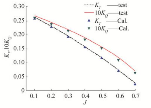
Fig. 5 shows the comparison between numerical and experimental results of the propeller thrust and torque coefficients in open-water conditions. It can be found that the calculated values have good agreement with the results from experimental tests. The numerical calculation model in the present work is validated as an effective and accurate approach for the thrust coefficients with an error of about 2% and the torque coefficient error is about 2.5% when J = 0.5.

|
Figure 5 Numerical and experimental results of open-water characteristics curves of the propeller (hs/D > 1.5) |
The advance speed of the propeller when the propeller is under wave conditions is given by:
| $ {V_A}' = {V_A} + {V_h} = {V_A} + a\omega \cos ({\pmb K} \cdot {\pmb x} - \omega t){{\bf{e}}^{Kz}} $ | (17) |
Meanwhile, the advance coefficient of the propeller under wave conditions is:
| $ J' = \frac{{{V_A}'}}{{nD}} $ | (18) |
Since this paper focuses only on the propeller hydrodynamic performance for a certain inflow velocity under wave conditions, the propeller advance coefficient is taken as a time average
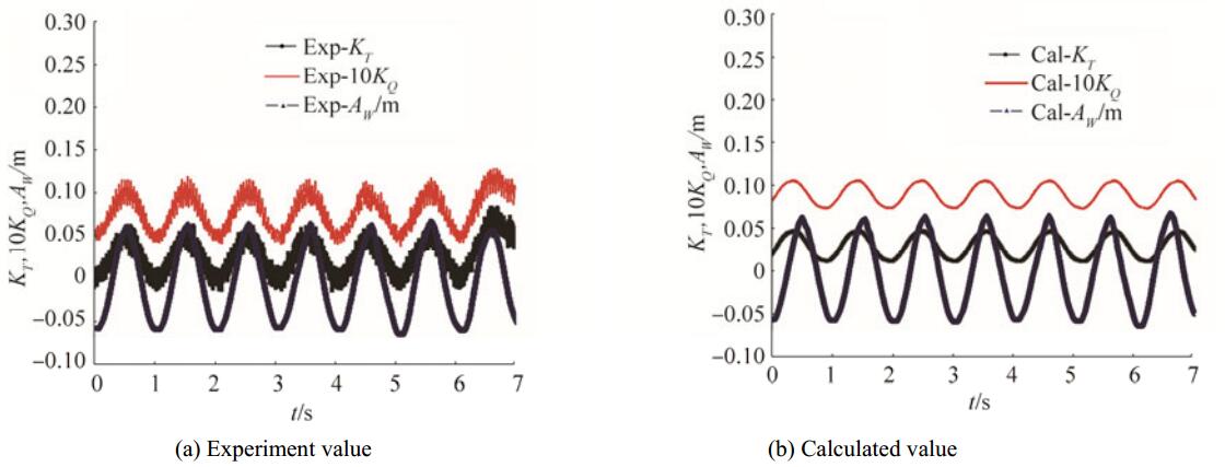
Unsteady hydrodynamics performance of the propeller with different submerging depths under wave conditions will be investigated. It should be noted that both the thrust and torque coefficients of the propeller in the previous chapter are also time averaged. Even when the propeller is working in still water with a sufficiently submerging depth, the period of thrust, and torque coefficients should be unsteady, the value should conform to the blade frequency, but the amplitude variation is small (2%-3%). Therefore, when the propeller works in wave conditions, it is not reasonable anymore to consider one period only. The unsteady characteristics of the propeller working in waves in the circulation water channel conditions with a propeller shaft depth, hs/D = 0.8 are to be analyzed. From Figures 6 and 7, the change of thrust coefficient KT, torque coefficient KQ, and the real-time wave height along Aw with the time in different velocities are displayed.

|
Figure 6 Unsteady characteristics of the propeller in waves (hs/D=0.8, J=0.3) |

|
Figure 7 Unsteady characteristics of the propeller in waves (hs/D=0.8, J=0.7) |
Unsteady characteristics of the propeller (both thrust and torque) are very visible under wave conditions. The changing amplitude of the thrust and torque coefficients is much larger, and the unsteady bearing force is obvious, so the unsteady features cannot be ignored when analyzing the propeller's unsteady characteristics under wave conditions. At the same time, the strength checking should also consider the unsteady features.
The unsteady period of the propeller is coincident with the wave period for the existence of the regular wave. The minimum thrust and torque appears in the wave trough, and the maximum of thrust and torque appears in the wave crest.
The periodicity of the thrust and torque coefficients becomes smooth and much more sinusoidal when the advance velocity is larger, but the periodicity changes abruptly when the advance velocity is smaller. It can be concluded that the propeller shaft bears a much more unsteady force at a smaller advance velocity.
The tendency and magnitude of the experimental value fluctuations are similar to the numerically calculated values except for the obvious roughness which is probably caused by the vibration of the actuating motor and instruments in the experiment.
Because of the good agreement between the experimental and numerical investigations, the numerical results will be displayed in Fig. 8 only. By comparing the data in Fig. 8, both thrust and torque coefficients (KT and KQ) in the regular wave can be found to be smaller than those in calm water. The propeller open-water efficiency in the regular waves is observed to be larger than that in calm water within the range of J = 0.45~0.6, however, generally, it can be concluded that the efficiency of the propeller working in waves is lower than that observed in calm water. From Fig. 8, we can see that both the thrust and torque coefficients in the regular waves are smaller than those in calm water. Though, the open-water efficiency in the regular waves is larger than that in calm water in some areas, it is redundant, since the decrease of thrust coefficient is smaller than that of the torque coefficient. Generally, the propeller propulsive efficiency reduces in waves.

|
Figure 8 Propeller open-water characteristic curves in calm water and in regular waves (numerical simulation) |
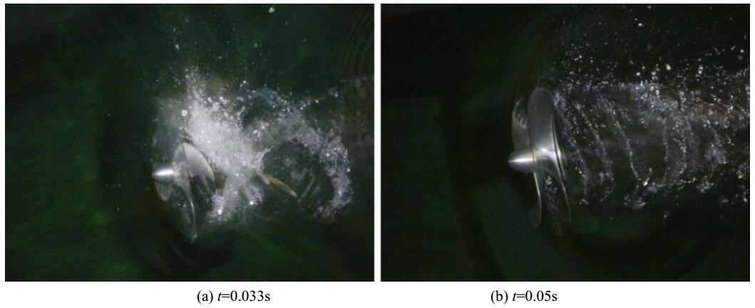
Fig. 9 shows the ventilation phenomenon during a wave period (t = 0, 0.017, 0.033, 0.05 s). From Fig. 9(a), the propeller functions well under the wave crest, and then the ventilation phenomenon begins to appear as shown in Fig. 9(b). The propeller performance is affected, and the thrust and torque are decreased to the level shown in Fig. 9(c). The air ingested by the propeller flows to the rear with the current as in Fig. 9(d), beyond that a new period begins. This phenomenon is coincident with the experimental phenomenon shown in Fig. 10. The ventilation phenomenon may lead to the flow separation on the propeller blade back which would form a low-pressure area. Then, the propeller propulsive efficiency reduces in waves with the decrease of thrust and torque.

|
Figure 9 The ventilation phenomenon in one wave period (J = 0.3, numerical simulation) |

|
Figure 10 The ventilation phenomenon in one wave period (J = 0.3, experimental phenomenon) |
Based on the experimental and numerical analyses of the propeller's hydrodynamic performance in calm water and waves, we can conclude that:
By comparing the propeller hydrodynamic performance in waves with that in calm water, it is not accurate to simply state that the propeller propulsive efficiency reduces in waves.
The important reason for the propeller's hydrodynamics performance change is the effluent and spatter phenomenon caused by the decreased depth of shaft.
The unsteady characteristics of the propeller in waves are very important. The changing amplitude of the thrust and torque coefficients is much larger, and the unsteady bearing force is obvious, so the unsteady features cannot be ignored when analyzing the propeller's unsteady characteristics under wave conditions.
Through comparing the experimental and numerical calculation results, we can summarize that the numerical simulation method has high accuracy when calculating the propulsive performance of the propeller under wave conditions.
Considering the limitation of the experimental conditions, there may be some external factors affecting the results during the experimental process, such as the height of the propeller's open-water tank, the levelness, and gradient of the open-water tank, vibration of the towing tank trailer and instruments, etc. All could affect the experiment. Therefore, the numerical simulation method has broad prospects.
In the experimental and numerical simulations, the regular wave parameters are constant. Some further research is still required, such as the propeller's performance in different irregular and regular waves, the method to calculate the open-water characteristic curves of the propeller while considering the horizontal velocity changes of the waves under wave conditions.
Arribas FP. Some methods to obtain the added resistance of a ship advancing in waves[J]. Ocean Engineering, 2007, 34: 946-955. DOI:10.1016/j.oceaneng.2006.06.002 ( 0) 0)
|
Aupoix B. Roughness corrections for the K-omega shear stress transport model:status and proposals[J]. Journal of Fluids Engineering-Transactions of the ASME, 2015, 137: 1-10. DOI:10.1115/1.4028122 ( 0) 0)
|
Bu JP, Lee CM, Lee SJ. Comparative measurements on the flow structure of a marine propeller wake between an open free surface and closed surface flows[J]. Journal of Marine Science and Technology, 2005, 10: 123-130. DOI:10.1007/s00773-004-0190-x ( 0) 0)
|
Califano A, Steen S. Numerical simulations of a fully submerged propeller subject to ventilation[J]. Ocean Engineering, 2011, 38(14-15): 1582-1599. DOI:10.1016/j.oceaneng.2011.07.010 ( 0) 0)
|
Cao ML. The open-water characteristics of a propeller with varying depth of shaft and in waves[J]. Journal of Shanghai Jiaotong University, 1988, 22(3): 27-35. ( 0) 0)
|
Chakraborty N, Cant RS. Effects of turbulent Reynolds number on turbulent scalar flux modeling in premixed flames using Reynolds-averaged Navier-Stokes simulations[J]. Numerical Heat Transfer Part a-Applications, 2015, 67: 1187-207. DOI:10.1080/10407782.2014.955375 ( 0) 0)
|
Cheng YZ, Wang YX, Jiang CB. A coopling model nonlinear wave and sandy seabed dynamic interaction[J]. China Ocean Engineering, 2007, 21(1): 77-89. ( 0) 0)
|
Ding H, 1998. The prediction of propeller's performance and stall in waves. MD thesis, Shanghai Jiaotong University, 68-78.
( 0) 0)
|
Faltinsen OM, Minsaas KJ, Liapis N, Skjordal SO. Prediction of resistance and propulsion of a ship in a seaway[J]. The Shipbuilders' Res Association of Japan, 1981: 505-529. ( 0) 0)
|
Guo CY, Zhao DG, Wang C, Chang X. Experimental research on hydrodynamic characteristics of propeller in waves[J]. Journal of Ship Mechanics, 2012, 16(9): 1005-1015. ( 0) 0)
|
Jia DS, Wang GQ, Cao ML, Sheng ZB. Air ventilation and hydrodynamic performance of propeller[J]. Journal of Shanghai Jiaotong University, 1990, 24(4): 32-41. ( 0) 0)
|
Kuang CP, Lee JH, Liu SG, Gu J. Numerical study on plume interaction above an alternating diffuser in stagnant water[J]. China Ocean Engineering, 2006, 20(2): 287-302. ( 0) 0)
|
Lee CS, 1983. Propeller in wave-state of the art. The proceedings of the Second International Symposium on Practical Design, Tokyo, Japan, 139-148.
( 0) 0)
|
Lee SK, Yu K, Chen HC, Tseng RK, 2010. CFD Simulation for propeller performance under seaway wave condition. Proceedings of the Twentieth (2010) International Offshore and Polar Engineering Conference, Beijing, China, 648-652.
( 0) 0)
|
Natio S, Nakamura S. Open-water characteristics and load fluctuations of propeller in waves[J]. Journal of Kansai Society of Naval Architects, 1975: 51-63. ( 0) 0)
|
Natio S, Nakamura S. Open-water characteristics and load fluctuations of propeller at racing conditions in waves[J]. Journal of Kansai Society of Naval Architects, 1979: 51-63. ( 0) 0)
|
Poranne R, Chen RJ, Gotsman C. On linear spaces of polyhedral meshes[J]. IEEE Transactions on Visualization and Computer Graphics, 2015, 21: 652-662. DOI:10.1109/TVCG.2014.2388205 ( 0) 0)
|
Tao YS, Ding H, Feng TC. An approximation method for calculating thrust variation of propeller in waves[J]. Journal of Ship Mechanics, 1999, 3(5): 1-6. ( 0) 0)
|
Tao YS, Zhang F, Feng TC. A study on propeller thrust and torque increase in regular waves[J]. Shipbuilding of China, 1991, 1: 47-57. ( 0) 0)
|
Tao YS, Zhou XY. The self-propelled factors and stall phenomenon of hooker in waves[J]. Shipbuilding Engineering, 1984, 3: 24-32. ( 0) 0)
|
Wang GQ, Jia DS. Influence of free surface on propeller characteristics[J]. Shipbuilding of China, 1989, 1: 1-8. ( 0) 0)
|
Yari E, Ghassemi H. Numerical study of surface tension effect on the hydrodynamic modeling of the partially submerged propeller's blade section[J]. Journal of Mechanics, 2016, 32(5): 653-664. DOI:10.1017/jmech.2016.38 ( 0) 0)
|
Yu X, 2008. Research on hydrodynamic performance of propeller in heaving conditions. MD thesis, College of Shipbuilding Engineering, Harbin Engineering University, 55-68.
( 0) 0)
|
 2017, Vol. 16


