Ocean exploration and an understanding of the underwater world are of utmost importance. To explore the deep seas, it is a necessity to design suitable appliances and equipment to negate the need for human presence in the undersea. To this end, a variety of unmanned submarines have been developed. Autonomous Underwater Vehicles (AUVs) or simply Underwater Vehicles (UWVs) are used in many applications such as measurement and sea-probing, exploration and exploitation of seabed minerals, inspection and maintenance of offshore structures, and anti-submarine warfare (Nematollahi et al., 2015). The operating conditions of AUVs at sea can be categorized into three types; at the sea-surface vicinity, at intermediate depths, and in the vicinity of the sea-floor. The main challenge for the design of underwater vehicles is to match their capabilities with different operating conditions while retaining maneuverability. The wave-making phenomena of the AUVs, while they are moving horizontally near the sea-surface, results in non-zero lift forces and pitch moments, even for axi-symmetric bodies. Due to these effects, providing dynamic stability for AUVs moving close to the sea-surface has great importance and complexity. During its operation, an AUV will experience frequent sea-surface effects, especially when receiving data from GPS navigation. For this reason, an assessment of the hydrodynamic loadings acting on subsea bodies close to the sea-surface and at different speeds is important. To evaluate the hydrodynamic performance of immersed moving AUVs, fluid-flow governing equations need to be accurately solved. Practically, as the forces and momentum in these equations are expressed in terms of hydrodynamic coefficients, these coefficients should be obtained before making a prototype. There are some experimental, semi-experimental, and numerical methods which can be used to compute the hydrodynamic coefficients of moving underwater bodies, especially for axi-symmetric bodies moving far from the sea-surface. However, when an immersed moving vehicle reaches the sea-surface vicinity, the coefficients calculated for high or intermediate depths are no longer valid and cannot be used to assess maneuverability and stability in these conditions. In this case, the dynamics of the body's motion is affected by the free-surface and some free-surface waves are induced. Prediction of the hydrodynamic coefficients of an AUV as a function of immersion depth is of utmost importance in engineering.
The overall resistance of AUVs moving near the sea-surface consists of two components: viscous resistance including friction and pressure, and wave-making resistance (Vorus et al., 2010). Recent advances in numerical techniques have provided affordable solutions for calculating hydrodynamic coefficients. Finite volume methods based on Computational Fluid Dynamics (CFD) are effective for simulating the effect of the water-surface on underwater bodies. In the field of identifying submarine hydrodynamic features at greater depths and far from the sea-surface, a lot of studies have been carried out by researchers in the form of laboratory tests and numerical methods. For example, Zhao et al. (2009) and Shao et al. (2013) numerically solved the steady flow around vertical and oblique cylinders. Laboratory experiments on the structure of flow around a cylinder, the coefficients of forces acting on it, and its effect on the water-surface have been carried out by Malavasi and Guadagnini (2007) considering various flow conditions and heights from a channel bottom.
Significant work has also been performed to predict the hydrodynamic coefficients of AUVs, for example studies by Phillips et al. (2010) Tang et al. (2009) Lee et al. (2011) and Ross et al. (2004). In comparison to the many studies that have been carried out on the hydrodynamic coefficients of immersed objects far from the free-surface conditions, few researchers have focused on two-phase flow and the free-surface effects on the hydrodynamic forces and moments of such bodies. Due to the complexity and nonlinearity of two-phase flow and the free-surface problem, only a few researchers, such as Hajmohammadi et al. (2014a; 2014b) have used analytical methods to solve their governing equations. Among the numerical work carried out to predict hydrodynamic forces on immersed bodies due to surface waves, the work of Wiley (1994) can be noted. Malik et al. (2013) also used CFD to calculate wave forces in both the time and frequency domains. In the above studies, the assumptions of potential flow, a slender body, and finite motion have been used and the accuracy of the results depends on the validity of these assumptions. A few researchers such as Jagadeesh et al. (2009; 2010) and Nematollahi et al. (2015) used the Reynolds averaged Navier Stokes, RANS equations to study the effect of a free-surface on the hydrodynamic coefficients of an axi-symmetric underwater body. All used full-turbulence models to analyze the hydrodynamics of these bodies. However, their results show considerable differences compared with experimental data, especially at low immersion depths.
As these bodies move at a relative lower speed underwater, the boundary layer regime over their surfaces may experience a transition from laminar to turbulent flow, and some regions might be exposed to laminar or transitional flows. Therefore, in this study, numerical results of CFD simulations around an underwater body in depth in vicinity of the free surface were obtained using two numerical turbulence/transition models. The full-turbulence model of k-ε and the four-equation transition model of Menter's Transition-SST (Menter et al., 2006), were compared with experimental data. Accounting for the effects of the transitional process from laminar to turbulent flow on these bodies is the novelty feature of this research.
2 Problem definitionIn this study, the hydrodynamic characteristics of an axi-symmetric body moving near the water surface, considering the effects of the laminar to turbulent transition process in the boundary layers is investigated numerically. The study was carried over the speed range 0.4 to 1.4 m/s and at immersion depths from 0.75 to 4 times the diameter of the body. Simulations were performed based on solving the RANS equations and using two turbulence/transition models: 1) the full-turbulence model of k-ε and 2) the four-equation turbulence/transition model of Menter's Transition-SST. Two transport equations in the second model were developed to predict the location of the transition onset from a laminar to turbulent regime, and the lengths of these transitions. This model also can simulate the turbulent regions of boundary layers as reported by Menter et al. (2006). Modeling of the laminar/turbulent transition is very important for the correct prediction of hydrodynamic characteristics of fluid flow as the transition substantially influences skin friction and therefore energy loss (Taghavi et al., 2006; 2008; 2009).
The hydrodynamic coefficients obtained from the simulations were then compared with the experimental results of Jagadeesh et al. (2009). A schematic of an axi-symmetric body is shown in Figure 1, where h is the distance from the water-surface and D is the maximum diameter of the body. Dimensionless parameters used in the simulation includes the Reynolds number Re=ρU∇1/3/μ ranging from 1.05×10⁵ -3.67×10⁵), immersion factor H=h/D ranging from 0.75 -4, and Froude number, Fr.

|
Figure 1 Schematic of a symmetrical AUV body |
For the hydrodynamic modeling of an AUV in the vicinity of a free-surface, the continuity, momentum, and a RANS based turbulence/transition model were solved for both air and water phases using the VOF approach. In the RANS equation, the Reynolds stresses,
The continuity and RANS equations are as follows:
| $\frac{{\partial {U_j}}}{{\partial {x_j}}} = 0$ | (1) |
| $\frac{{\partial {U_i}}}{{\partial t}} + \left({{U_j}\frac{{\partial {U_i}}}{{\partial {x_j}}} + \frac{{\partial \overline {{u_i}{u_j}} }}{{\partial {x_j}}}} \right) = - \frac{{\partial P}}{{\partial {x_j}}} + \frac{1}{{Re}}{\nabla ^2}{U_i}$ | (2) |
The transport equations of the k-ε full-turbulence model need to be solved to obtain the Reynolds stresses, as follows:
| $\frac{{\partial k}}{{\partial t}} + \left({{U_j} - \frac{1}{{{\sigma _k}}}\frac{{\partial {\nu _t}}}{{\partial {x_j}}}} \right)\frac{{\partial k}}{{\partial {x_j}}} = \frac{1}{{{R_k}}}{\nabla ^2}k + G - \varepsilon $ | (3) |
| $\frac{{\partial \varepsilon }}{{\partial t}} + \left({{U_j} - \frac{1}{{{\sigma _\varepsilon }}}\frac{{\partial {\nu _t}}}{{\partial {x_j}}}} \right)\frac{{\partial \varepsilon }}{{\partial {x_j}}} = \frac{1}{{{R_\varepsilon }}}{\nabla ^2}\varepsilon + \frac{\varepsilon }{k}\left({{C_{\varepsilon 1}}G - {C_{\varepsilon 2}}\varepsilon G} \right)$ | (4) |
In the above equations, Ui represents the main components of velocity, p is the pressure, and G is the level of kinetic energy production. Other details of the model can be seen in Jagadeesh et al. (2010). The Menter's Transition-SST turbulence/transition model was developed by Menter et al. (2006) to model the laminar, transitional, and turbulence features in transitional flows. It can predict the location of transition onset based on empirical correlations and can also provide an estimation of the length of the transition region. It should be noted, that the development of RANS-based transition/turbulence models for predicting transitional flows has been of more interest since the year 2000. A literature review on transitional fluid-flow simulations can be found in Taghavi et al. (2006; 2008; 2009).
The Menter's Transition-SST turbulence/transition model is a powerful tool for modeling transitional flows. This model has four transport equations: two for predicting the transition onset and evaluating intermittency within the transitional region, and the other two for modeling turbulence characteristics using the k-ω-SST turbulence model. The k-ω-SST model benefits both the k-ω and k-ε turbulence models and was in good agreement with the experimental results. The first equation of the Menter's Transition-SST turbulence/transition model is the intermittency transport equation, used for evaluating the laminar/turbulence quantities within the transition region. The transport equation for the intermittency, γ, is as follows:
| $\begin{array}{l} \frac{{\partial \left({\rho \gamma } \right)}}{{\partial t}} + \frac{{\partial \left({\rho {U_j}\gamma } \right)}}{{\partial {x_j}}} = {P_{\gamma 1}} - {E_{\gamma 1}} + \\ {P_{\gamma 2}} - {E_{\gamma 2}} + \frac{\partial }{{\partial {x_j}}}\left[ {\left({\mu + \frac{{{\mu _t}}}{{{\sigma _\gamma }}}} \right)\frac{{\partial \gamma }}{{\partial {x_j}}}} \right] \end{array}$ | (5) |
The second transport equation transports a scalar variable called the transition's Reynolds number of momentum thickness,
| $ \frac{{\partial \rho {u_j}{{\widetilde {Re}}_{\theta t}}}}{{\partial {x_j}}} = {P_{\theta t}} + \frac{\partial }{{\partial {x_j}}}\left[ {{\sigma _{\theta t}}\left({\mu + {\mu _t}} \right)\frac{{\partial {{\widetilde {Re}}_{\theta t}}}}{{\partial {x_j}}}} \right] $ | (6) |
The third and fourth transport equations of this turbulence/transition model are same as the equations of the k-ω-SST turbulence model.
To solve the transport equations, a commercial CFD code (Fluent 16.0) was used. This is based on the finite volume method. The SIMPLE algorithm was also used for coupling the pressure and velocity fields within the domain. A second-order upwind was used for discretizing the momentum and turbulence/transition models.
4 Multiphase modelingThe main issues for modeling in this present work were the computational simulation of the water free-surface and capture of the relevant surface-wave propagation. Two common methods are proposed in the literature to perform these simulations; the marker-and-cell (MAC) and the VOF. Both have the ability for nonlinear simulation and wave-breaking. The MAC method calculates the free-surface by recording the momentum of fluid particles. This method requires the location of each particle therefore; it often occupies a large amount of storage space and needs considerable computing time (Tome and McKee et al., 1994). In contrast, the VOF method is more consistent with many engineering applications, including the calculation of free-surface flow (Shen et al., 2004; Zhao et al., 2010). In the present work, the VOF model was used to calculate surface waves made by the underwater body moving near the water free-surface. The governing principals of the VOF method, developed by Hirt and Nichols (1981) are based on the conservation of mass and momentum for two or more non-miscible fluids. It has been used to detect the interface between fluid phases. In this method, the fluid phase in a computational cell is modeled by the volume fraction of each fluid, such that their fractions are between zero and one, and their sum is equal to one.
Mathematical equations to measure the volume fraction αi can be expressed as follows:
| $\frac{{\partial {\alpha _i}}}{{\partial t}} + {\pmb{U}} \times \nabla {\alpha _i} = 0$ | (7) |
| $\mathop \sum \limits_{i = 1}^2 {\alpha _i} = 1$ | (8) |
| $\rho = {\alpha _1}{\rho _1} + \left({1 - {\alpha _1}} \right){\rho _2}$ | (9) |
where ρ1 and ρ2 are the densities of two different types of immiscible fluids.
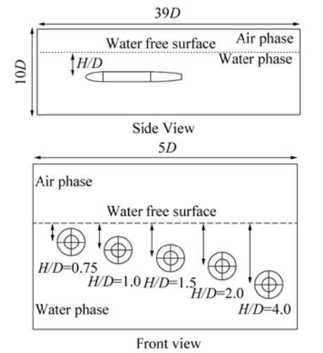
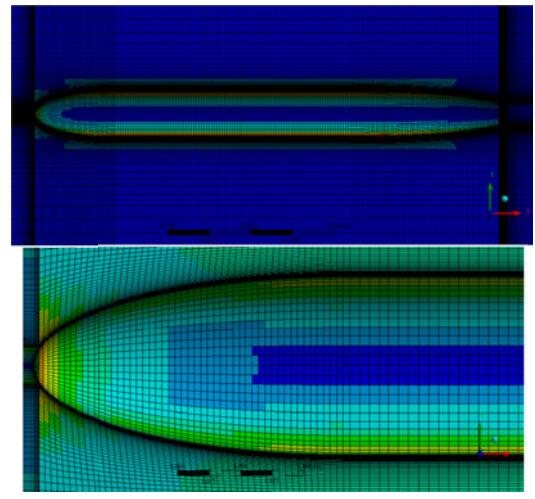
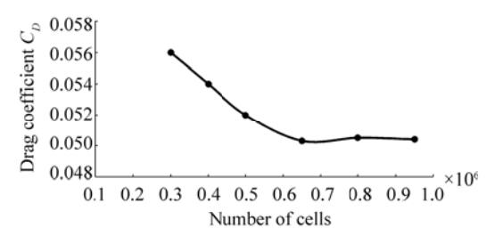
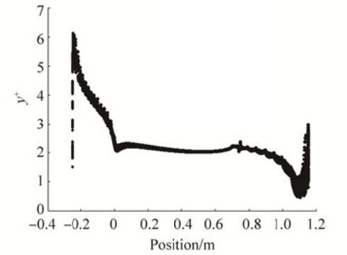
5 The computational domain and boundary conditionsFor the numerical simulation, a 3D computational domain of 39D×10D×5D was used according to Jagadeesh et al., (2009). The computational domain is shown in Figure 2. A schematic of the immersion depths of the body is also shown. At the entrance to the domain, the inlet pressure boundary condition was set by the two parameters of speed and free-surface height. The boundary condition of the output pressure at the outlet was characterized by determining the height of the free-surface. The upper and lower boundaries of the domain were set as a slipping wall. The side boundary surfaces were adjusted to a symmetrical plane. To discretizing the computational domain a structured mesh was used (Fig. 3). To better capture the flow-field quantities close to the free-surface, smaller cells were used at the water/air boundary. To ensure that the numerical results remained independent of the number of cells within the computational domain, and to select adequate cell sizes for the smaller cells nearest to the body's surface, the number and size of cells were changed for body speeds of 1.4 m/s and depths of h/D = 0.75. Table 1 shows number of cells that can be achieved in the domain corresponding to the range of y+. Figure 4 shows the drag or resistance coefficient dependency on the number of cells in the computational domain. According to these results, for a domain with over 0.8 million cells, the drag/resistance coefficient does not change significantly. Fig. 5 shows the variations in y+ for the selected case of E in Table 1.
|
Figure 2 Schematic of the computational domain |
|
Figure 3 Schematic of the structured grid |
|
|
Table 1 Different cases for domain meshing |
|
Figure 4 Study of the grid independency |
|
Figure 5 Variations in y+ along the body for the case of E of Table 1 and [H = 0.75D, 1.4 m/s] |
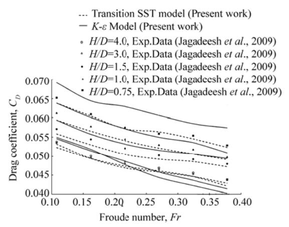
The hydrodynamic characteristics of an underwater vehicle, with a body of revolution subjected to the effects of a water free-surface, were investigated numerically. Hydrodynamic coefficients were determined over the speed range 0.4 to 1.4 m/s (Re = 3.67×10⁵) and at different depths of H (0.75D -4.0D). For the simulation, two different turbulence/transition models were used and the results compared with the experimental data obtained by Jagadeesh et al.(2009, 2010). In this study, the results are presented for different immersion depths, according to the dimensionless number
|
Figure 6 Variation in drag coefficient versus Froude number at different depths |
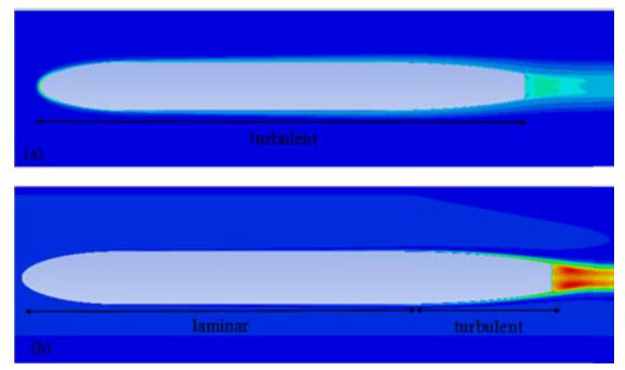
The intermittency in the Menter's SST-Transition model, Eq. (5), indicates turbulent or laminar features within the fluid flow field. It has a maximum value of one within the fully-turbulent region and a minimum value of zero in the fully-laminar region. In the transition region the intermittency varies from zero to one.
The basic difference between the full-turbulence k-ε model and Menter's SST-Transition model is the determination of the transitional region in the latter model. In the k-ε model, the whole boundary layer around the body is assumed to be turbulent, while in the transition/turbulence Menter model, the laminar, transitional and turbulent boundary layers are distinguishable. The turbulent kinetic energy contours and the intermittency factor are shown in Figs. 7 and 8, respectively. Fig. 7(a) shows the turbulent kinetic energy of the k-ε model at Fr = 0.11. As mentioned, in this turbulence model, the whole boundary layer region is assumed to be turbulent, which is different in reality. Fig. 7(b) shows the turbulent kinetic energy computed by Menter's SST-Transition model at Fr = 0.11. Fig. 7(b) shows that the SST-Transition model has enough capability to capture the transitional boundary layers, from laminar to turbulent. In Fig. 8, the intermittency coefficient over the body surface, obtained from the SST-transition model, is shown for the same flow conditions as used for the results in Fig. 7.
|
Figure 7 Contours of turbulent kinetic energy; a) k-ε turbulence model and b) Menter's SST-Transient model |

|
Figure 8 Variations in intermittency over the body surface, computed using Menter's SST-Transition model (laminar region, blue; turbulent region, red) |
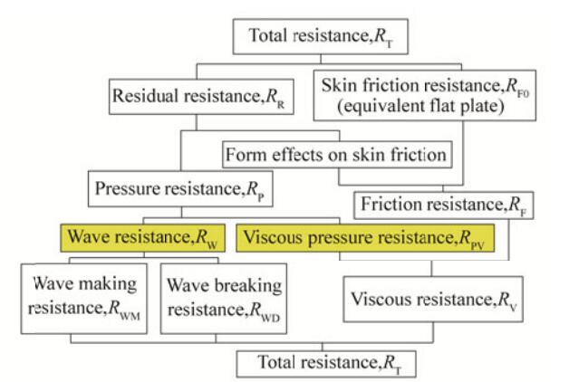
By reducing the immersion depth of the underwater body, its interaction with the water-surface increases, therefore, an additional term, the wave-making resistance, should be added to the overall drag of the body, similar to that obtained for deep-sea conditions. In hydrodynamic studies of AUVs, the wave-making drag/resistance is an important parameter. The wave-making resistance is defined as the difference between the total body drag while moving in the water-surface vicinity and that under deep-sea conditions, where there is not any interaction between the body and the water-surface. For this comparison, the same speed and angle of attack conditions are considered.
An analysis and classification of resistance forces in marine applications is shown in Fig. 9, which provides different levels of resistance forces (Bertram, 2012; Rawson, 2001). A basic and well-known classification for overall resisting force in marine engineering is the sum of wave resistance, pressure resistance, and friction resistance, RT = RW + RPV + RF. According to this definition, the pressure resistance is as follows: RP = RW + RPV.
|
Figure 9 The components of total resistance RT in marine applications (Rawson, 2001) |
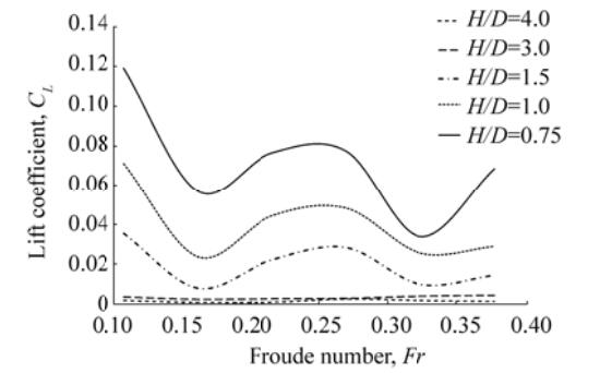
As expected, the reason for the increase in total resistance or drag coefficient with reducing immersion depth is the increase in the wave-making resistance component on the underwater body. However, for greater immersion depths, the wave-making resistance partially decreases or fully removed. The results show that for an immersion depth H > 3D the wave-making resistance is negligible. Fig. 10 shows the effect of the free-surface on the lift coefficient, CL, when the underwater body moves in the water-surface vicinity. This figure shows that when the underwater body moves in a depth H > 3D, due to the symmetry condition of the flow fields around the body, the lateral force tends to be very small and negligible. As the immersion depth decreases, the flow field around the underwater body will be asymmetric and lateral forces and pitch moments will be created while the body moves horizontally. For these AUV configurations, the lateral force is positive and upward, so it lifts the body up toward the water-surface.
|
Figure 10 Variation in lift coefficient, CL, versus Froude number, Fr, at different depths |
The effects of underwater body motion on the water-surface profiles at different speeds can be also obtained. Fig. 11 shows the water free-surface or wave profiles at the speed of u = 1.4 m/s for various depths. It is evident that by decreasing the immersion depth, the relevant wave height increases. It was also observed that for H > 3, no considerable wave was generated on the water-surface.
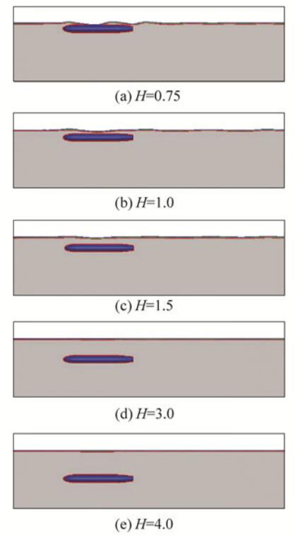
|
Figure 11 Water free-surface profile characteristics versus immersion depth, u=1.4 m/s and Fr=0.38 |
Fig. 12 shows the effect of speed variation of the underwater body on wave profiles for the depth H=0.75D. It can be observed that with increasing body speed, the generated wave height also increases. The wavelength also increases and is approximately equal to the length of underwater body. At low speeds, the wavelength is lower and hence the wave frequency on body increases.

|
Figure 12 Water free-surface profile due to underwater body motion at H=0.75D under different speeds |
In this paper, a set of numerical simulations of two-phase flow were conducted to evaluate the effects of moving in the vicinity of a water free-surface on the hydrodynamic coefficients of an AUV. The results were compared with the experimental results of Jagadeesh et al. (2009) and showed good agreement. This study was performed at different depths from H = 0.75D to H = 4D, and with different Froude numbers,
Bertram V, 2012. Practical ship hydrodynamics. Elsevier. http://www.sciencedirect.com/science/article/pii/B9780750648516500084
( 0) 0)
|
Hajmohammadi MR, Nourazar SS. On the insertion of a thin gas layer in micro cylindrical Couette flows involving power-law liquids[J]. International Journal of Heat and Mass Transfer, 2014a, 75(31): 97-108. DOI:10.1016/j.ijheatmasstransfer.2014.03.065 ( 0) 0)
|
Hajmohammadi MR, Nourazar SS, Campo A. Analytical solution for two-phase flow between two rotating cylinders filled with power law liquid and a micro layer of gas[J]. Journal of Mechanical Science Technology, 2014b, 28(5): 1849-1854. DOI:10.1007/s12206-014-0332-y ( 0) 0)
|
Hirt CW, Nichols BD. Volume of fluid (VOF) method for the dynamics of free boundaries[J]. Journal of computational physics, 1981, 39(1): 201-25. DOI:10.1016/0021-9991(81)90145-5 ( 0) 0)
|
Jagadeesh P, Murali K. RANS predictions of free surface effects on axisymmetric underwater body[J]. Engineering Applications of Computational Fluid Mechanics, 2010, 4(2): 301-313. DOI:10.1080/19942060.2010.11015318 ( 0) 0)
|
Jagadeesh P, Murali K, Idichandy VG. Experimental investigation of hydrodynamic force coefficients over AUV hull form[J]. Journal of Ocean Engineering, 2009, 36(1): 113-118. DOI:10.1016/j.oceaneng.2008.11.008 ( 0) 0)
|
Lee SK, Joung TH, Cheo SJ, Jang TS, Lee JH. Evaluation of the added mass for a spheroid-type unmanned underwater vehicle by vertical planar motion mechanism test[J]. International Journal of Naval Architecture and Ocean Engineering, 2011, 3(3): 174-180. DOI:10.2478/IJNAOE-2013-0060 ( 0) 0)
|
Malavasi S, Guadagnini A. Interactions between a rectangular cylinder and a free-surface flow[J]. Journal of Fluids and Structures, 2007, 23(8): 1137-1148. DOI:10.1016/j.jfluidstructs.2007.04.002 ( 0) 0)
|
Malik SA, Pan G, Liu YA. Numerical simulations for the prediction of wave forces on underwater vehicle using 3D panel method code[J]. Research Journal of Applied Sciences, Engineering and Technology, 2013, 5(21): 5012-5021. ( 0) 0)
|
Menter FR, Langtry RB, Likki SR, Suzen YB, Huang PG, V ِ lker S. A correlation-based transition model using local variablespart I:model formulation[J]. Journal of Turbomachinery, 2006, 128(3): 413-422. DOI:10.1115/1.2184352 ( 0) 0)
|
Nematollahi A, Dadvand A, Dawoodian M. An axisymmetric underwater vehicle-free surface interaction:a numerical study[J]. Journal of Ocean Engineering, 2015, 96: 205-214. DOI:10.1016/j.oceaneng.2014.12.028 ( 0) 0)
|
Phillips A, Turnock SR, Furlong M. The use of computational fluid dynamics to aid cost-effective hydrodynamic design of autonomous underwater vehicles[J]. Proceedings of the Institution of Mechanical Engineers, Part M:Journal of Engineering for Maritime Environment, 2010, 224(4): 239-254. DOI:10.1243/14750902JEME199 ( 0) 0)
|
Rawson KJ, 2001. Basic ship theory. Vol. 1, Butterworth-Heinemann.
( 0) 0)
|
Ross A, Fossen TI, Johansen TA. Identification of underwater vehicle hydrodynamic coefficients using free decay tests[J]. IFAC Conference on Control Applications in Marine Systems, Ancona, Italy, 2004. ( 0) 0)
|
Shao WY, Zhang YP, Zhu DZ, Zhang TQ. Drag force on a free surface-piercing yawed circular cylinder in steady flow[J]. Journal of Fluids and Structures, 2013, 43: 145-163. DOI:10.1016/j.jfluidstructs.2013.09.007 ( 0) 0)
|
Shen YM, Ng CO, Zheng YH. Simulation of wave propagation over a submerged bar using the VOF method with a two-equation k–ε turbulence modeling[J]. Journal of Ocean Engineering, 2004, 31(1): 87-95. DOI:10.1016/S0029-8018(03)00111-2 ( 0) 0)
|
Taghavi ZR, Salari M. Prediction of Boundary Layer Transition at High Freestream Turbulence Conditions Using a Physical Model[J]. Aerospace Mechanics Journal, 2006, 2(2): 85-95. ( 0) 0)
|
Taghavi ZR, Salari M, Etemadi M. Prediction of laminar, transitional and turbulent flow regimes, based on three-equation k-ω turbulence model[J]. Aeronautical Journal, 2008, 112(1134): 469-476. DOI:10.1017/S0001924000002438 ( 0) 0)
|
Taghavi ZR, Salari M, Kolaei A. Prediction of boundary layer transition based on modeling of laminar fluctuations using RANS approach[J]. Chinese Journal of Aeronautics, 2009, 22(2): 113-120. DOI:10.1016/S1000-9361(08)60076-X ( 0) 0)
|
Tang S, Ura T, Nakatani T, Thornton B, Jiang T. Estimation of the hydrodynamic coefficients of the complex-shaped autonomous underwater vehicle TUNA-SAND[J]. Journal of Marine Science and Technology, 2009, 14(3): 373-386. DOI:10.1007/s00773-009-0055-4 ( 0) 0)
|
Tome MF, McKee S. GENSMAC:A computational marker and cell method for free surface flows in general domains[J]. Journal of Computational Physics, 1994, 110(1): 171-186. DOI:10.1006/jcph.1994.1013 ( 0) 0)
|
Vorus WS, Paulling JR, 2010. The Principles of Naval Architecture Series. http://ci.nii.ac.jp/ncid/BB16857751
( 0) 0)
|
Willy CJ, 1994. Attitude control of an underwater vehicle subjected to waves. Ph. D thesis, Massachusetts Institute of Technology and Woods Hole Oceanographic Institute. http://agris.fao.org/agris-search/search.do?recordID=AV2012099075
( 0) 0)
|
Zhao M, Cheng L, Zhou T. Direct numerical simulation of three-dimensional flow past a yawed circular cylinder of infinite length[J]. Journal of Fluids and Structures, 2009, 25(5): 831-847. DOI:10.1016/j.jfluidstructs.2009.02.004 ( 0) 0)
|
Zhao XZ, Hu CH, Sun ZC. Numerical simulation of extreme wave generation using VOF method[J]. Journal of Hydrodynamics, Ser. B, 2010, 22(4): 466-477. DOI:10.1016/S1001-6058(09)60078-0 ( 0) 0)
|
 2017, Vol. 16


