2. Department of Ocean Engineering and Naval Architecture, Indian Institute of Technology Kharagpur, Kharagpur 721302, India
Gravity wave transformation due to change in bottom topography is of fundamental importance in the understanding of wave energy distribution in continental shelves and is a key issue in coastal zone management. Due to global warming, there is a rise in the occurrences of storm surges which adversely affect coastal regions. As a part of the development of warning system for disaster mitigation, several measures are taken to predict the effect of wave transformation in coastal regions. Among various costal processes associated with wave transformation due to variation in bottom bed geometry, combined effect of refraction and diffraction of waves is well attributed by the mild-slope type models which are also known as depth-integrated equations. The mild-slope model is based on the assumption that bottom slope is mild and was first derived by Berkhoff (1972) using vertical averaging procedure which was re-derived by Smith and Sprinks (1975) using Green's second identity in a lucid manner. However, Berkhoff's equation neglects the terms concerned with higher order bottom effects namely square of the bottom slope and bottom curvature with the mild-slope assumption. Using variational principle and retaining these neglected terms Chamberlain and Porter (1995) derived a new depth-integrated equation, known as the Modified Mild-Slope Equation (MMSE). It was shown that the effects of both the curvature and slope-squared terms are important in understanding combined refraction and diffraction. Further, Porter and Staziker (1995) extended the MMSE to include the influence of any number of evanescent modes and provided expressions to be used at the bottom slope discontinuities to ensure mass conservation at those points. The MMSE with mass conserving jump conditions works very well for bottom slopes up to 1. Also, in the case of sinusoidal ripple beds, results from MMSE were verified by the experimental data of Davies and Heathershaw (1984) and found favorable agreement. A good treatment of mild-slope equations can be found in Porter (2003). An extensive literature on mild-slope models and the development of boundary element method for solving mild-slope equations can also be obtained from Cerrato et al. (2016). In addition, the MMSE was extended to study water wave scattering by floating structures over uneven bottom such as a floating ice-sheet which has been modeled as an elastic plate (see Porter and Porter (2004)), a flexible membrane (see Manam and Kaligatla, 2012; Kaligatla and Manam, 2016).
Of late, study on wave interaction with coastal structures such as breakwaters has received considerable progress because of their direct impact on various coastal activities including shore protection, creation of tranquility zones in ports and harbors, environmental protection, recreation and miliary operations. Especially, for reduction of wave reflection and load on coastal infrastructures, wave absorbing structures such as porous structures have often been used due to their ability in dissipating wave energy. Models involving porous structures fixed near sea walls have been proposed for creating tranquility zones near harbors/ports/bays. Use of such breakwaters with dissipation characteristics is much acceptable due to their well performance in reducing wave loads on rigid sea walls.
Michael et al. (1998) analyzed interaction between waves and surface-piercing partial vertical slotted barrier by using eigenfunction expansion method. The excellent review of Chwang and Chan (1998) illustrates the theory for waves past porous structures as well as the use of those structures as wavemakers and as breakwaters to reduce resonance in harbors. Sahoo et al. (2000b) investigated the role of thin partial porous barrier in various vertical positions in trapping and generation of waves in semi-infinite fluid region by using the method of eigen function expansion and the least square method while the problem was again considered by Sahoo et al. (2000a) for oblique waves. Huang et al. (2011) reviewed the recent progress on the hydraulic performance and wave loadings of perforated/ slotted coastal structures. Koley et al. (2014) considered a wave trapping system consisting of porous barriers of finite width kept in front of a sea wall and solved the problem by applying eigen function expansion method and multi-domain boundary-element method. Apart from the use of single barriers, there is a significant interest in the use of dual barriers which can act as an effective breakwater system for protecting marine facilities. Liu and Li (2011) investigated the effectiveness of dual barriers which consists of pervious barrier in the seaside and rigid impervious barrier in the shoreward as a wave absorber. Karmakar et al. (2013) studied the performance of multiple surface-piercing permeable membrane wave barriers and have shown the occurrence of Bragg resonance in reflection coefficient. Karmakar and Soares (2014) studied scattering of water waves by multiple bottom-standing flexible porous wave barriers and found that the transmitted wave height can be reduced significantly due to the presence of multiple barriers. Mondal and Gayen (2015) investigated wave interaction with dual circular porous plates in deep water using hyper singular integral equation technique. Recently, Mandal et al. (2015) analyzed wave scattering by multiple porous flexible barriers, arranged in uniform depth of water, by applying wide-spacing approximation method.
However, when waves reach from open sea to shoreline, they bring with them and remove sand and other debris. Clay or mud and small rocks deposited by waves result in silting up of deep water channels/harbours which is often act as a hindrance in the navigational passage. One of the simplest ways for overcoming this awkward situation is achieved by introducing a step down in sea bottom bed near the bay/harbor mouth (see Billingham and King (2000)). The consideration of step down bottoms in the design of wave trapping models motivates to study its effect on waves that are incident on step while interacting with coastal structures. Suh and Park (1995) developed a model for predicting wave reflection from a perforated-wall caisson breakwater mounted on rubble mound foundation. They employed Galerkin eigen function method of Massel (1993) which is associated with depth-integrated model and studied reflection of oblique waves from that structure. Applying the matched eigen function expansion method Bhattacharjee and Guedes Soares (2011) studied diffraction of obliquely incident waves by a floating rigid structure near a wall with a bottom of vertical step. Das and Bora (2014) considered a model consisting of a porous structure on multi-step type bottom before a sea wall and analyzed oblique wave damping by the porous structure. Some of the recent developments on wave-structure interaction problems involving step type bottom can be found in Dhillon et al. (2016). But, a bottom with varying step is more realistic than a bottom with vertical step(s). Behera et al. (2015) developed a wave trapping model involving a sea bottom with varying step and a thin porous barrier placed near a sea wall. In the wave trapping problem studied in this paper, emphasis was given to find the criteria for creating a tranquility zone with minimum load on the sea wall. They used MMSE with interfacial matching conditions of Porter and Staziker (1995) in the varying bottom region and obtained reflection coefficient of waves, force on the barrier and wall. Behera et al. (2016) studied the oblique wave scattering by a bottom-standing or surface-piercing flexible porous barrier in water of finite depth having bottom undulation using the methods of least-squares and multi-mode approximation associated with the modified mild-slope equation. In most of the studies in the literature concerned with wave trapping by porous barrier near a wall, emphasis was given on the role of single porous barrier of varied configurations for creating minimum load on the barrier and the sea wall.
In the present study, oblique wave trapping by a pair of porous barriers located near a rigid wall is analyzed in the presence of undulated bottom bed. The physical problem is studied under the assumption of small amplitude water wave theory and Darcy's law is used to analyze wave past porous structures whilst, modified mild-slope equation is used to deal with the uneven bottom bed. In the uniform water depth regions, velocity potentials are expanded using the eigen function expansions. On the other hand, in the region of variable bottom, the modified mild-slope model is used to obtain the velocity potentials. Then, the solution of the MMSE is matched with the velocity potentials in the uniform bed regions to obtain a system of equations for the determination of unknown physical quantities. Moreover, mass conserving jump conditions are applied to account for slope discontinuity in bottom bed profile. Various physical quantities such as reflection coefficient and wave forces on the wall and the porous barriers, and surface wave elevation are computed and analyzed to understand the roles of depth ratio, angle of incidence, structural porosity, length of varying bottom, gap between the barriers and wall for an effective wave trapping system.
2 Formulation of the boundary value problemIn this Section, oblique wave trapping by a pair of thin porous barriers is formulated in the Cartesian coordinate system in the presence of varying bottom topography. The physical problem is studied under the assumption of the linearized water wave theory and the porous barrier is assumed to have fine pores. The problem is considered in the three dimensional Cartesian co-ordinate system with x-y plane being the mean free surface in the horizontal direction and negative z-axis being in the vertically downward direction. The problem is formulated assuming that the fluid is inviscid and incompressible and the flow is irrotational and simple harmonic in time. The fluid domain is divided into five sub-regions based on the geometry of the problem as shown in Fig. 1. Two thin porous barriers having fine pores are considered and are fixed vertically from bottom to free surface at finite distances in front of a rigid wall. In this arrangement, first barrier is the one which is close to the undulated bed whilst, the second barrier is the one which is close to rigid wall. Moreover, the distance between the two barriers is assumed to be L1 and the gap between the second barrier and the wall is assumed to be L as in the Fig. 1. Assuming the bottom bed is uniform in y-direction, the varying bottom bed profile is represented by

|
Figure 1 Schematic diagram of wave trapping system involving dual porous barriers |
| $ \left(\frac{{{\partial }^{2}}}{\partial {{x}^{2}}}+\frac{{{\partial }^{2}}}{\partial {{z}^{2}}}-\beta _{y}^{2} \right){{\phi }_{j}}=0\text{ } $ | (1) |
The free surface boundary condition is
| $ \frac{\partial {{\phi }_{j}}}{\partial z}-K{{\phi }_{j}}=0\text{, on }z=0\text{, for }j=\text{ 1, 2, 3, 4, 5} $ | (2) |
where K= ω2 / g and g is the gravitational constant.
The boundary condition on the uniform bottoms are given by
| $ \frac{\partial {{\phi }_{j}}}{\partial z}=0\text{ on }z=-{{h}_{j}}\text{ for }j=1\text{, 3, 4, 5} $ | (3) |
and the boundary condition for the varying bottom is written as
| $ \frac{\partial {{\phi }_{2}}}{\partial z}+\frac{\text{d}h}{\text{d}x}\frac{\partial {{\phi }_{2}}}{\partial x}=0\text{ on }z=-h(x), 0\le x\le {{L}_{3}} $ | (4) |
On the rigid vertical wall, the no flow condition in the horizontal direction yields
| $ \frac{\partial {{\phi }_{5}}}{\partial x}=0\text{ at }x={{L}_{3}}+{{L}_{2}}\text{+ }{{L}_{1}}+L $ | (5) |
The boundary conditions on the porous barriers at x = L3 +L2 and x =L3 +L2 + L1 are given by (as in Behera et al., 2015)
| $ \begin{align} &\frac{\partial {{\phi }_{3}}}{\partial x}=\frac{\partial {{\phi }_{4}}}{\partial x}\text{ and }\frac{\partial {{\phi }_{j}}}{\partial x}=\text{i}{{\beta }_{0}}{{G}_{1}}({{\phi }_{3}}-{{\phi }_{4}})\text{ } \\ &\text{ for }-{{h}_{2}}\le z\le 0, \text{ }j=3, 4 \\ \end{align} $ | (6) |
and
| $ \begin{align} &\frac{\partial {{\phi }_{4}}}{\partial x}=\frac{\partial {{\phi }_{5}}}{\partial x}\text{ and }\frac{\partial {{\phi }_{j}}}{\partial x}=\text{i}{{\beta }_{0}}{{G}_{2}}({{\phi }_{4}}-{{\phi }_{5}})\text{ } \\ &\text{ for }-{{h}_{2}}\le z\le 0, \text{ }j=4, 5 \\ \end{align} $ | (7) |
respectively, where G1 and G2 are complex porous effect parameters. In general, according to Yu (1995) the complex porous effect parameters have been defined as
| $ {{G}_{1}}=\frac{{{\varepsilon }_{1}}({{f}_{1}}+\text{i}{{s}_{1}})}{{{\beta }_{0}}{{d}_{1}}(f_{1}^{2}+s_{1}^{2})}, \text{ }{{G}_{2}}=\frac{{{\varepsilon }_{2}}({{f}_{2}}+\text{i}{{s}_{2}})}{{{\beta }_{0}}{{d}_{2}}(f_{2}^{2}+s_{2}^{2})}\text{ } $ | (8) |
with ε1, ε2 are the porosity of the barriers, f1, f2 are the resistance coefficients, s1, s2 are the inertial coefficients, d1, d2 the thickness of the porous barriers. The real and imaginary parts of the complex porous-effect parameters in G1 and G2 correspond to the linearized resistance effect of the porous medium against the flow and inertia effect of the fluid inside the porous medium, respectively. The inertial coefficients s1, s2may simply be taken as unity (see Li et al., 2006; Suh et al., 2011). The values of the resistance coefficients f1, f2 must be estimated through experiments. An empirical formula for this resistance coefficient was provided by Suh et al. (2011). The transparency of the porous structure may be increased by increasing both the parts of the porous parameter. The porous-effect parameter can be considered as a real number (Chwang, 1983) when the resistance effect of the porous medium dominates the inertial effect.
Finally, the radiation condition is given by
| $ {{\phi }_{1}}=\left({{A}_{0}}{{\text{e}}^{\text{i}{{p}_{0}}x}}+{{R}_{0}}{{\text{e}}^{-\text{i}{{p}_{0}}x}} \right)\frac{\cosh {{\beta }_{0}}(z+{{h}_{1}})}{\cosh {{\beta }_{0}}{{h}_{1}}}\text{ as }x\to -\infty $ | (9) |
where A0 is prescribed incident wave amplitude and R0 is corresponding reflected wave amplitude that is to be determined and p0= β0 cos θ.
3 Method of solutionFor the solution of the physical problem described above, method of eigen function expansion is applied in each subdomain and solutions are matched at the interface boundaries. Since the bottom is varying in the finite interval (0, L3) and is uniform outside this interval, MMSE is employed in (0, L3). The bottom profile is assumed to be continuously differentiable function in (0, L3) and is allowed to have slope discontinuities at x=0 and x=L3. The solution of the MMSE is matched with the solutions in the uniform bottom regions at these slope discontinuous points. Moreover, mass conserving jump conditions as in Porter and Staziker (1995) are used at these points. In region 1, the unknown velocity potential ϕ1 is written as
| $ \begin{align} &\ \ \ \ \ \ \ {{\phi }_{1}}(x, z)={{A}_{0}}{{\text{e}}^{\text{i}{{p}_{0}}x}}{{f}_{0}}({{\beta }_{0}}, z)+\sum\limits_{n=0}^{\infty }{{{R}_{n}}{{\text{e}}^{-\text{i}{{p}_{n}}x}}}{{f}_{n}}({{\beta }_{n}}, z) \\ &\text{where}\ \ \ \ {{f}_{n}}({{\beta }_{n}}, z)=\cosh{{\beta }_{n}}(z+{{h}_{1}})/\cosh{{\beta }_{n}}{{h}_{1}} \\ &\text{with}\ \ \ \ \ \ \ \ \ {{p}_{n}}=\sqrt{\beta _{n}^{2}-\beta _{y}^{2}}\text{ for }n=0, \text{ }1, \text{ }2, \text{ }3, \text{ }... \\ \end{align} $ | (10) |
The constant A0 is a known amplitude of an incident wave and R0 being an unknown amplitude of the corresponding reflected wave that is to be determined along with the unknowns Rn. Here, β0 is the positive real root and βn for n=1, 2, 3, ... are the purely imaginary roots of the dispersion equation βtanh βh1=K in β. These roots can be found numerically. In region 2, the velocity potential ϕ2 is written as
| $ {{\phi }_{2}}(x, z)=\sum\limits_{n=0}^{\infty }{{{\psi }_{n}}(x){{Z}_{n}}(h, z)}\text{ } $ | (11) |
where
| $ {{Z}_{n}}=\cosh {{k}_{n}}(z+h)/\cosh {{k}_{n}}h $ |
The wave number k0 is a positive real root and k1, k2, k3, ... are purely imaginary roots of the dispersion equation k tanh kh=K in k. In contrast to the uniform bottom case, here the roots k0, k1, k2, k3... are functions of x as they depend on the bottom function h(x). The eigenfunctions Zn are borrowed from the flat bottom solution and kn is being considered as function of x. This is the key assumption for the development of mild-slope equations. It is to be noted that Eq. (11) is an approximation for the velocity potential ϕ2(x, z). In the regions 3, 4 and 5, the velocity potentials ϕ3, ϕ4 and ϕ5 are expressed as
| $ {{\phi }_{3}}(x, z)=\sum\limits_{n=0}^{\infty }{({{B}_{n}}{{\text{e}}^{\text{i}{{q}_{n}}x}}+{{C}_{n}}{{\text{e}}^{-\text{i}{{q}_{n}}x}}){{g}_{n}}({{\gamma }_{n}}, z)} $ | (12) |
| $ {{\phi }_{4}}(x, z)=\sum\limits_{n=0}^{\infty }{({{D}_{n}}{{\text{e}}^{\text{i}{{q}_{n}}x}}+{{E}_{n}}{{\text{e}}^{-\text{i}{{q}_{n}}x}}){{g}_{n}}({{\gamma }_{n}}, z)} $ | (13) |
| $ \text{and }{{\phi }_{5}}(x, z)=\sum\limits_{n=0}^{\infty }{{{M}_{n}}\cos {{q}_{n}}(x-{{x}_{1}}){{g}_{n}}({{\gamma }_{n}}, z)} $ | (14) |
respectively, where
A differential equation for the unknown function
| $ \int_{-h}^{0}{\left({{\phi }_{2}}\frac{{{\partial }^{2}}{{Z}_{m}}}{\partial {{z}^{2}}}-{{Z}_{m}}\frac{{{\partial }^{2}}{{\phi }_{2}}}{\partial {{z}^{2}}} \right)}\text{d}z=\left[ {{\phi }_{2}}\frac{\partial {{Z}_{m}}}{\partial z}-{{Z}_{m}}\frac{\partial {{\phi }_{2}}}{\partial z} \right]_{z=-h}^{z=0} $ | (15) |
It may be noted that the function Zm satisfies
| $ \begin{matrix} \frac{{{\partial }^{2}}{{Z}_{m}}}{\partial {{z}^{2}}}-k_{m}^{2}{{Z}_{m}}=0, \text{ }-h<z<0;\text{ }\frac{\partial {{Z}_{m}}}{\partial z}-K{{Z}_{m}}=0, \text{ }z=0;\text{ } \\ \frac{\partial {{Z}_{m}}}{\partial z}=0, \text{ }z=-h\text{ } \\ \end{matrix} $ | (16) |
On utilizing Eqs. (1), (2), (4) and (16) in the expression (15), we get
| $ \int_{-h}^{0}{\left(k_{m}^{2}{{Z}_{m}}{{\phi }_{2}}+{{Z}_{m}}\left[ \frac{{{\partial }^{2}}{{\phi }_{2}}}{\partial {{x}^{2}}}-\beta _{y}^{2}{{\phi }_{2}} \right] \right)}\text{d}z=-{{\left[ {{Z}_{m}}\frac{\text{d}h}{\text{d}x}\frac{\partial {{\phi }_{2}}}{\partial x} \right]}_{z=-h}} $ | (17) |
The approximation (11) for ϕ2can be sought and then Eq. (17) becomes
| $ \begin{align} &\sum\limits_{n=0}^{N}{\left\{ \left(k_{m}^{2}{{\psi }_{n}}+\frac{{{\text{d}}^{2}}{{\psi }_{n}}}{\text{d}{{x}^{2}}}-\beta _{y}^{2}{{\psi }_{n}} \right)\int_{-h}^{0}{{{Z}_{m}}{{Z}_{n}}\text{d}z} \right.}+ \\ &\text{ }{{\psi }_{n}}\int_{-h}^{0}{{{Z}_{m}}\frac{{{\partial }^{2}}{{Z}_{n}}}{\partial {{x}^{2}}}\text{d}z}+2h'\text{ }\int_{-h}^{0}{{{Z}_{m}}\frac{\partial {{Z}_{n}}}{\partial h}\text{d}z\frac{\text{d}{{\psi }_{n}}}{\text{d}x}}+ \\ &\text{ }\left. {{\left[ {{Z}_{m}}{{Z}_{n}}h'\frac{d{{\psi }_{n}}}{dx}+{{\psi }_{n}}{{(h')}^{2}}{{Z}_{m}}\frac{\partial {{Z}_{n}}}{\partial h} \right]}_{z=-h}} \right\}=0\text{ } \\ \end{align} $ | (18) |
where h' and h" are first and second order derivatives of h respectively. This equation can further be simplified by applying the following identity which is derived by Leibniz rule.
| $ \begin{align} &\frac{\text{d}}{\text{d}x}\int_{-h}^{0}{{{Z}_{m}}{{Z}_{n}}\frac{\text{d}{{\psi }_{n}}}{\text{d}x}\text{d}z-}\int_{-h}^{0}{{{Z}_{n}}\frac{\partial {{Z}_{m}}}{\partial h}\text{d}z\text{ }h'\frac{\text{d}{{\psi }_{n}}}{\text{d}x}=} \\ &\text{ }h'\int_{-h}^{0}{{{Z}_{m}}\frac{\partial {{Z}_{n}}}{\partial h}\text{d}z\frac{\text{d}{{\psi }_{n}}}{\text{d}x}}\text{+}\int_{-h}^{0}{{{Z}_{m}}{{Z}_{n}}\text{d}z\frac{{{\text{d}}^{2}}{{\psi }_{n}}}{\text{d}{{x}^{2}}}}\text{+} \\ &\text{ }h'{{\left[ {{Z}_{m}}{{Z}_{n}} \right]}_{z=-h}}\frac{\text{d}{{\psi }_{n}}}{\text{d}x}\text{ } \\ \end{align} $ | (19) |
Finally, using the orthogonal property
| $ \begin{align} &\frac{\text{d}}{\text{d}x}\left({{a}_{m}}\frac{\text{d}{{\psi }_{m}}}{\text{d}x} \right)+\left(k_{m}^{2}-\beta _{y}^{2} \right){{a}_{m}}{{\psi }_{m}}+ \\ &\sum\limits_{n=0}^{N}{\left[ \left({{b}_{nm}}-{{b}_{mn}} \right)h'\frac{\text{d}{{\psi }_{n}}}{\text{d}x}+\left\{ {{b}_{nm}}h''+{{c}_{nm}}{{\left(h' \right)}^{2}} \right\}{{\psi }_{n}} \right]}=0 \\ \end{align} $ | (20) |
where
| $ \begin{align} &{{a}_{m}}(h)=\int_{-h}^{0}{Z_{m}^{2}\text{d}z}\text{, }{{b}_{nm}}(h)=\int_{-h}^{0}{{{Z}_{m}}\frac{\partial {{Z}_{n}}}{\partial h}}\text{d}z\text{, } \\ &\text{ }{{c}_{nm}}(h)=\frac{\text{d}{{b}_{nm}}}{\text{d}h}-\int_{-h}^{0}{\frac{\partial {{Z}_{m}}}{\partial h}\frac{\partial {{Z}_{n}}}{\partial h}}\text{d}z\text{, for }m=0, \text{ }1, \text{ }2, \text{ }..., N. \\ \end{align} $ |
Eq. (20) can be solved numerically for the functions
| $ \left. \begin{align} &{{\psi }_{0}}(x)={{A}_{0}}{{\text{e}}^{\text{i}{{p}_{0}}x}}+{{R}_{0}}{{\text{e}}^{-\text{i}{{p}_{0}}x}} \\ &{{\psi }_{n}}(x)={{R}_{n}}{{\text{e}}^{-\text{i}{{p}_{n}}x}} \\ \end{align} \right\}\text{at }x=0\text{ for }n=1, \text{ 2, }...\text{, }N $ | (21) |
and
| $ \left. \begin{align} &{{\psi }_{0}}(x)={{B}_{0}}{{\text{e}}^{\text{i}{{q}_{0}}x}}+{{C}_{0}}{{\text{e}}^{-\text{i}{{q}_{0}}x}} \\ &{{\psi }_{n}}(x)={{B}_{n}}{{\text{e}}^{\text{i}{{q}_{n}}x}}+{{C}_{n}}{{\text{e}}^{-\text{i}{{q}_{n}}x}} \\ \end{align} \right\}\text{at }x={{L}_{3}}\text{ for }n=1, \text{ 2, }...\text{, }N $ | (22) |
Further, to ensure the conservation of mass across the interface boundaries at x=0 and L3, using expressions for
| $ \begin{array}{l} \left. \begin{array}{l} {a_0}\frac{{{\rm{d}}{\psi _0}}}{{{\rm{d}}x}} + {\rm{i}}{p_0}{a_0}{\psi _0} + h'\sum\limits_{m = 0}^N {{b_{m0}}{\psi _m}} = 2{\rm{i}}{p_0}{a_0}{A_0}\\ {a_n}\frac{{{\rm{d}}{\psi _n}}}{{{\rm{d}}x}} + {\rm{i}}{p_n}{a_n}{\psi _n} + h'\sum\limits_{m = 0}^N {{b_{mn}}{\psi _m}} = 0 \end{array} \right\}\\ \;\;\;\;\;\;\;\;\;\;\;\;\;\;\;\;\;\;\;\;\;\;\;\;\;\;\;\;\;\;\;\;\;\;\;\;\;{\rm{at }}\;\;x = 0 + {\rm{ }},{\rm{ }}n = 1,{\rm{ }}2,{\rm{ }}...,N \end{array} $ | (23) |
| $ \begin{array}{l} \left. \begin{array}{l} {a_0}\frac{{{\rm{d}}{\psi _0}}}{{{\rm{d}}x}} - {\rm{i}}{q_0}{a_0}{\psi _0} + h'\sum\limits_{m = 0}^N {{b_{m0}}{\psi _m}} = - 2{\rm{i}}{q_0}{a_0}{C_0}{{\rm{e}}^{ - {\rm{i}}{q_0}x}}\\ {a_n}\frac{{{\rm{d}}{\psi _n}}}{{{\rm{d}}x}} - {\rm{i}}{q_n}{a_n}{\psi _n} + h'\sum\limits_{m = 0}^N {{b_{mn}}{\psi _m}} = - 2{\rm{i}}{q_n}{a_n}{C_n}{{\rm{e}}^{ - {\rm{i}}{q_n}x}} \end{array} \right\}\\ \;\;\;\;\;\;\;\;\;\;\;\;\;\;\;\;\;\;\;\;\;\;\;\;\;\;\;\;\;\;\;\;\;\;\;\;\;{\rm{ at }}\;\;x = {L_3} - ,{\rm{ }}n = 1,{\rm{ }}2,{\rm{ }}...,N \end{array} $ | (24) |
Finally, the expansions in Eqs. (12)-(14) are used in the conditions in Eqs. (6) and (7) which yield
| $ \begin{array}{l} \left. \begin{array}{l} \sum\limits_{n = 0}^N {\left\{ \begin{array}{l} {\rm{i}}{q_n}{B_n}{{\rm{e}}^{{\rm{i}}{q_n}x}} - {\rm{i}}{q_n}{C_n}{{\rm{e}}^{ - {\rm{i}}{q_n}x}} - \\ {\rm{i}}{q_n}{D_n}{{\rm{e}}^{{\rm{i}}{q_n}x}} + {\rm{i}}{q_n}{E_n}{{\rm{e}}^{ - {\rm{i}}{q_n}x}} \end{array} \right\}{J_{mn}} = 0} ,\\ \sum\limits_{n = 0}^N {\left\{ \begin{array}{l} [{\rm{i}}({q_n} - {\beta _0}{G_1}){B_n} + {\rm{i}}{\beta _0}{G_1}{D_n}]{{\rm{e}}^{{\rm{i}}{q_n}x}} + \\ [ - {\rm{i}}({q_n} + {\beta _0}{G_1}){C_n} + {\rm{i}}{\beta _0}{G_1}{E_n}]{{\rm{e}}^{ - {\rm{i}}{q_n}x}} \end{array} \right\}{J_{mn}} = 0} , \end{array} \right\}\\ \;\;\;\;\;\;\;\;\;\;\;\;\;\;\;\;\;\;\;\;\;\;\;\;\;\;\;\;\;\;\;\;\;\;\;\;\;\;\;\;\;\;\;\;\;\;\;\;\;\;\;\;{\rm{at }}\;\;x = {L_2} + {L_3} \end{array} $ | (25) |
and
| $ \begin{array}{l} \left. \begin{array}{l} \sum\limits_{n = 0}^N {\left\{ \begin{array}{l} {\rm{i}}{q_n}{D_n}{{\rm{e}}^{{\rm{i}}{q_n}x}} - {\rm{i}}{q_n}{E_n}{{\rm{e}}^{ - {\rm{i}}{q_n}x}} + \\ {q_n}{M_n}\sin {q_n}(x - {x_1}) \end{array} \right\}{J_{mn}} = 0} ,\\ \sum\limits_{n = 0}^N {\left\{ \begin{array}{l} {\rm{i}}{\beta _0}{G_2}({D_n}{{\rm{e}}^{{\rm{i}}{q_n}x}} + {E_n}{{\rm{e}}^{ - {\rm{i}}{q_n}x}}) + \\ {M_n}[{q_n}\sin {q_n}(x - {x_1}) - \\ {\rm{ i}}{\beta _0}{G_2}\cos {q_n}(x - {x_1})] \end{array} \right\}{J_{mn}} = 0} , \end{array} \right\}\\ \;\;\;\;\;\;\;\;\;\;\;\;\;\;\;\;\;\;\;\;\;\;\;\;\;\;\;\;\;\;\;\;\;\;\;\;\;\;\;\;\;\;\;\;\;\;\;\;\;\;\;\;{\rm{at }}\;\;x = {L_1} + {L_2} + {L_3} \end{array} $ | (26) |
where
| $ {{J}_{mn}}=\int_{-h}^{0}{{{g}_{m}}{{g}_{n}}\text{d}z}, \text{ for }m, n=0, \text{ }1, \text{ }2, \text{ }..., N $ |
Eq. (20) provides a system of N+1 second order coupled linear ordinary differential equations. In the present paper, for numerical results we have used only one mild-slope equation related to propagating wave mode which is referred as the single mode approximation in literature as in Chamberlain and Porter (1995). For a large class of mild-slope models, the single mode approximation gives reasonable accuracy for realistic physical problems. For example, Bennetts et al. (2009) observed that higher modes have negligible contribution in the study of interaction of flexural gravity waves with periodic geometry in a floating ice sheet. As the mild-slope equation in ψ0 is of second order, its general solution has two unknown constants K1, K2(say). Thus, the unknown constants B0, C0, D0, E0, M0, R0 along with K1 and K2 can be determined by solving numerically Eqs. (21)-(26).
4 Numerical resultsIn this Section, numerical results are presented to analyze the role of dual barriers in trapping surface gravity waves. In order to solve the modified mild-slope equation numerically, the in-built function NDSolve is employed in Mathematica. For numerical results, a fixed wave length of plane gravity wave
| $ {{K}_{r}}=\left| {{R}_{0}}/{{A}_{0}} \right| $ | (27) |
| $ {{C}_{f}}={{\left. \text{i}\rho \omega \int_{-{{h}_{2}}}^{0}{\left\{ {{\phi }_{4}}(x, z)-{{\phi }_{3}}(x, z) \right\}} \right|}_{x=({{L}_{3}}+{{L}_{2}})}}\text{d}z $ | (28) |
| $ {{C}_{g}}={{\left. \text{i}\rho \omega \int_{-{{h}_{2}}}^{0}{\left\{ {{\phi }_{5}}(x, z)-{{\phi }_{4}}(x, z) \right\}} \right|}_{x=({{L}_{3}}+{{L}_{2}}+{{L}_{1}})}}\text{d}z\text{ } $ | (29) |
| $ {{C}_{w}}={{\left. \text{i}\rho \omega \int_{-{{h}_{2}}}^{0}{{{\phi }_{5}}(x, z)} \right|}_{x={{x}_{1}}}}\text{d}z $ | (30) |
where Cf, Cg and Cw are the forces acting on the first and second barriers and on the wall respectively. Further, the non-dimensional forms of the horizontal wave forces on the porous barriers and rigid wall are denoted as F1, F2 and Fw and are given by
| $ {{F}_{1}}=\frac{\left| {{C}_{f}} \right|}{\rho gh_{1}^{2}}, \text{ }{{F}_{2}}=\frac{\left| {{C}_{g}} \right|}{\rho gh_{1}^{2}}\text{ and }{{F}_{w}}=\frac{\left| {{C}_{w}} \right|}{\rho gh_{1}^{2}} $ | (31) |
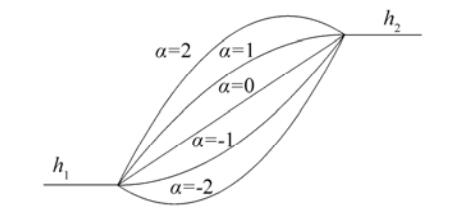
Here, the bed profiles shown in Fig. 2 are considered using the bed function h(x) as
| $ \begin{align} &h(x)={{h}_{1}}-({{h}_{1}}-{{h}_{2}})\left\{ 1-\alpha {{(1-x/{{L}_{3}})}^{2}}+(\alpha -1)(1-x/{{L}_{3}}) \right\} \\ &\;\;\;\;\;\;\;\;\;\;\;\;\;\;\;\;\;\;\;\;\;\;\;\;\;\;\;\;\;\;\;\;\;\;\;\;\;\;\;\;\;\;\;\;\;\;\;\;\;\;\;\;\;\;\;\;\;\;\;\;\;\text{}0<x<{{L}_{3}} \\ \end{align} $ | (32) |
|
Figure 2 Bottom profiles for different values of α |
where α = 0 corresponds to a plane sloping step type bed, α ≥ 1 corresponds to a protrusion above the depth h2, and for
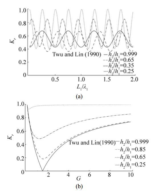
In Figs. 3(a) and (b), results of the present problem are compared with Figs. 2 and 4 of Twu and Lin (1990) pertaining to wave trapping by two porous barriers and a wall in the presence of uniform bottom. Results of Twu and Lin (1990) are recovered by choosing h2/h1 almost one in computation as a limiting case. The parameter values
|
Figure 3 Reflection coefficient Kr versus (a) L1/λ1 with G=5, L2/λ1=0.4 and (b) porous effect parameter G where G1=G, G2=2G with L1/λ1=0.5, L2/λ1=0.5 for different values of depth ratio h2/h1 |
|
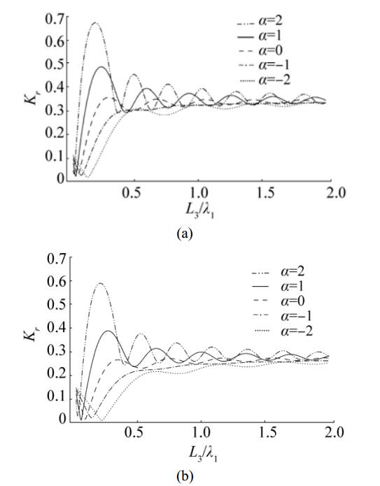
Figure 4 Reflection coefficient Kr versus L3/λ1 for different values of α and for (a) λ=0º and (b) λ=30º with G1=1+i, G2=1+i, h2/h1=0.25, L/λ1=0.4, L1/λ1=0.4, L2/λ1=0.4 |
For each value of the depth ratio h2/h1 reflection coefficient is periodic as in Twu and Lin (1990) and it increases significantly for smaller values of h2/h1. Moreover, phase shift in the reflection coefficient is observed when h2/h1 decreases form one and the points L1/λ1 at which minimum reflection occurs increase as the depth ratio h2/h1 decreases due to the presence of step type varying bottom. Fig. 3(b) shows reflection coefficient versus porous effect parameter G where G1=G, G2=2G for different values of depth ratio h2/h1. In water of uniform depth, Twu and Lin (1990) showed that when the distance between the wall and porous barrier is half of the distance between two porous barriers, whether G1=G, G2=2G or G1=2G, G2=G there was no change in the reflection coefficient and full wave was trapped at G=1.5. However, this is not the case in the presence of varying bottom and the minimum in reflection increases as the depth ratio h2/h1 decreases. In Fig. 3(b) it can be seen that higher reflection of wave occurs for larger absolute values of G and smaller values of depth ratio h2/h1.
The reflection coefficient Kr is plotted versus the non-dimensional horizontal length of the varying bed L3/λ1 for various values of bed shape parameter α for normally incident waves in Fig. 4(a) and for oblique incident waves with θ=30º in Fig. 4(b). In general, wave reflection is more in case of normally incident waves compared to obliquely incident waves. Moreover, wave reflection is highest in case of α > 1 and lowest for bed having depression with α < -1.
Further, wave reflection is very small for smaller values of L3/λ1 which attains an oscillatory steady state as L3/λ1 increases. However, the amplitude in the oscillatory pattern decreases for larger values of L3/λ1. A comparison with Fig. 3 of Behera et al. (2015) reveals that there is a significant reduction in wave reflection in case of wave trapping by two barriers compared to that of the single barrier.
|
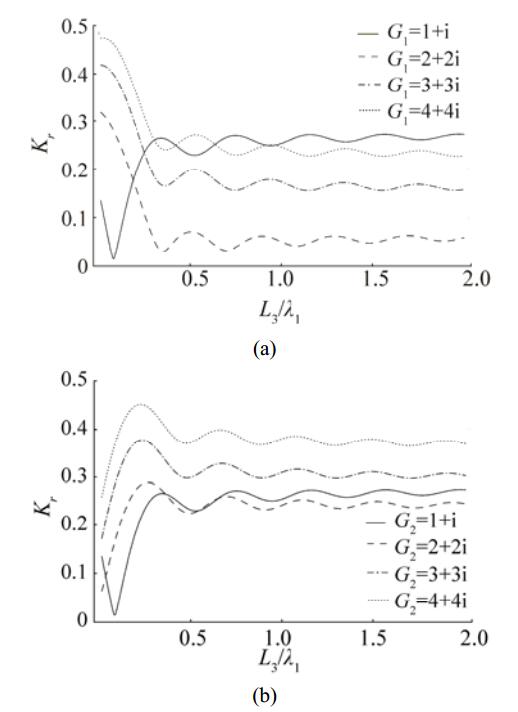
Figure 5 Reflection coefficient Kr versus L3/λ1 for different values of (a) G1 while G2=1+i is fixed and (b) G2 while G1=1+i is fixed, with θ=30º, α=0, h2/h1=0.25, L2/λ1=0.4, L1/λ1=0.4, L/λ1=0.4 |
In the subsequent discussion, the results are computed and analyzed for plane sloping bed which corresponds to α=0. Figs. 5(a) and (b) show the variations of the reflection coefficient versus the non-dimensional horizontal length of the varying bed L3/λ1 for different values of the porous-effect parameters of the barriers. Both the figures reveal that with an increase in the absolute value of the porous-effect parameter of the first barrier, there is a significant reduction in wave reflection compared to the second barrier. However, for smaller values of L3/λ1, wave reflection is more for first barrier compared to the second barrier. Further, minimum wave reflection is observed for G1 =2+2i and G2 =1+i for the first barrier and for G1 =1+i and G2 =2+2i for the second barrier.
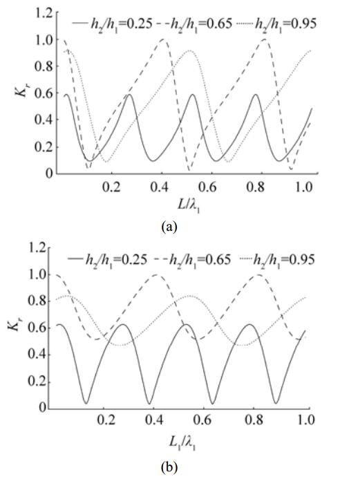
Fig. 6(a) shows the variations of the reflection coefficient versus the non-dimensional distance L/λ1 between the second barrier and the rigid wall for different values of depth ratio h2/h1. Fig. 6(a) demonstrates that wave reflection follows an oscillatory periodic pattern as the distance L/λ1 increases. However, as depth ratio h2/h1 increases, the amplitude of the oscillatory pattern in wave reflection increases. The increase in amplitude may be due to the fact that effect of wave transformation due to increase in the depth ratio h2/h1 is decreasing significantly. Further, there is a phase shift in the oscillatory pattern of wave reflection due to an increase in depth ratio h2/h1. Fig. 6(b) shows the variations of the reflection coefficient versus the non-dimensional distance L1/λ1 between the two barriers for different values of depth ratio h2/h1. Fig. 6(b) illustrates that for higher values of depth ratio h2/h1, minimum reflection increases significantly as depth ratio h2/h1 increases. Moreover, as the distance between the barriers increases, wave reflection follows an oscillatory periodic pattern which is similar to that observed in Fig. 6(a). Both the figures reveal that with an increase in depth ratio h2/h1, number of optima in wave reflection decreases for fixed gap length between the barriers as well as the barrier and the rigid wall.
|
Figure 6 Reflection coefficient Kr versus (a) L/λ1 for fixed L1/λ1=0.4 and (b) L1/λ1 for fixed L/λ1=0.4 and for different values of h2/h1 with G1=2+2i, G2=1+i, θ=0º, L2/λ1=0.4, L3/λ1=1 |
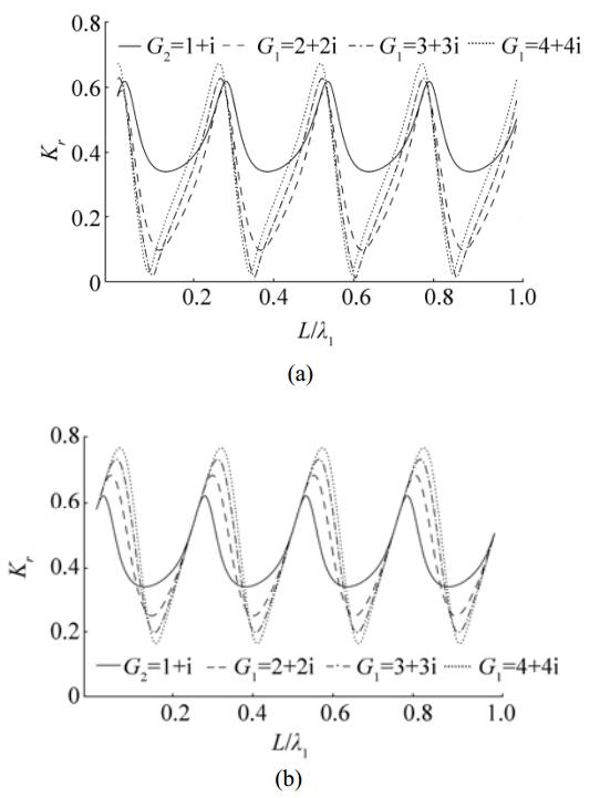
Fig. 7 shows the variations of the reflection coefficient versus the non-dimensional distance L/λ1 between second barrier and the rigid wall for different values of porous-effect parameters. Both the figures reveal that the reflection coefficient follows a periodic oscillatory pattern as the distance between the second barrier and the wall increases which is similar to Fig. 6. A comparison between Figs. 7(a) and 7(b) shows that more wave energy is reflected with an increase in the absolute value of the porous-effect parameter G2 of the barrier close to the rigid wall which demonstrates that more wave energy is trapped due to the barrier close to the undulated bed. Further, Fig. 7(b) reveals that a major increase in the maximum values of wave reflection occur due to the change in the porosity of the second barrier.
|
Figure 7 Variations of reflection coefficient Kr versus L/λ1 for (a) different values of G1 while G2=1+i is fixed and (b) different values of G2 while G1=1+i is fixed, with h2/h1=0.25, θ=0º, L1/λ1=0.4, L2/λ1=0.4, L3/λ1=1 |
Fig. 8 demonstrates the variations of the reflection coefficient versus the non-dimensional distance L1/λ1 between the two barriers for different values of porous-effect parameters. These figures depict that wave reflection follows an oscillatory periodic pattern as the non-dimensional distance L1/λ1 increases which is similar to the observation made in Fig. 7. Fig. 8(a) reveals that with an increase in the absolute value of the porous-effect parameter G1 of the first barrier, wave reflection decreases considerably. On the other hand, a reverse trend in wave reflection is observed with an increase in the absolute value of the porous-effect parameter G2 of the second barrier. A comparison between Figs. 8(a) and 8(b) illustrates that the first barrier having higher porosity plays a significant role in trapping most of the wave energy.

|
Figure 8 Variations of reflection coefficient Kr versus L1/λ1 for (a) different values of G1 while G2=1+i is fixed and (b) different values of G2 while G1=2+2i is fixed, with h2/h1=0.25, θ=0º, L/λ1=0.3, L2/λ1=0.4, L3/λ1=1 |
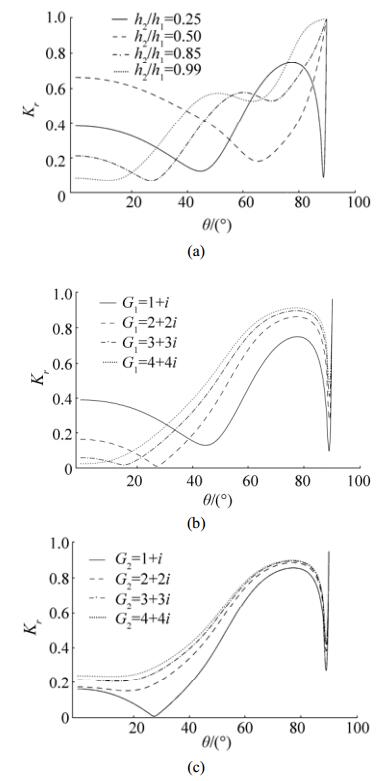
Fig. 9 illustrates the variations of the reflection coefficient as a function of angle of incident θ. Particularly, Fig. 9(a) demonstrates Kr for varying depth ratio h2/h1 while Figs. 9(b) and 9(c) represent Kr for varying porous-effect parameter. Fig. 9(a) depicts that there exist two minima in reflection when h2/h1=0.25and a sharp variation in reflection is arising at larger incident wave angles in the range 80º -90º. This is due to linear slopping bed with small depth ratio values. However, the sharp variation is diminishing remarkably as the depth ratio h2/h1 is tending to one. As a result, the two minima in wave reflection reduces to a single minimum. Also, it is observed that in the case of almost flat bottom, minimum in wave reflection occurs for smaller angles between 0º and 15º. In Figs. 9(b) and 9(c), effect of variation of porous-effect parameter on wave reflection is explored for smaller depth ratio h2/h1=0.25. Both the figures illustrate that due to the presence of two barriers, there exist two minima in the reflection coefficients for two different angles of incidence for certain values of porous-effect parameters and often zero minimum in reflection is also observed. Fig. 9(b) reveals that with an increase in the absolute value of the porous-effect parameter G1 of the first barrier, one of the minima in reflection occurs for smaller angle of incidence. This shift in reflection may be due to a change in phase of the incident and reflected waves as the absolute value of the porous-effect parameter increases. On the other hand, Fig. 9(c) depicts that with an increase in the absolute value of the porous-effect parameter G2 of the second barrier, one of the minima is disappearing which may be due to dissipation of incident wave energy by the porous barriers.
|
Figure 9 Variation of reflection coefficient Kr versus the angle of incidence θ for (a) different values of depth ratio h2/h1=0.25 with G1=1+i and G2=1+i, (b) different values of G1 with G2=1+i and (c) different values of G2 with G1=2+2i. Various fixed parameters are h2/h1=0.25, L/λ1=0.3, L1/λ1=0.3, L2/λ1=0.4, L3/λ1=1 |
In Figs. 10(a) and (b), reflection coefficients versus angle of incidence θ are plotted for different values of non-dimensional distance L/λ1 between the second barrier and the wall, and L1/λ1 between the two porous barriers respectively. It is observed that with an increase in L/λ1, there is a right shift in the minima with an increase in θ and the minimum in wave reflection which occurs for higher angle of incidence diminishes. A similar pattern is also observed in Fig. 10(b) when the non-dimensional distance L1/λ1 between the porous barriers increases. Thus, both the figures demonstrate that the minima close to the higher angle of incidence diminishes with an increase in the gap between the barriers, or the barrier and wall. However, when the gap between the barriers increases more waves will be trapped in comparison to the increase in the distance between the second barrier and the wall for smaller angle of incidence.

|
Figure 10 Reflection coefficient Kr versus the angle incidence θ for (a) different values of L/λ1 while L1/λ1=0.3 is fixed and (b) different values of L1/λ1 while L/λ1=0.3is fixed, with G1=2+2i, G2=1+i, h2/h1=0.25, L2/λ1=0.4, L3/λ1=1 |
Figs. 11(a) and (b) show the variations of horizontal wave force acting on the rigid wall Fw versus the non-dimensional distance L/λ1 between the second barrier and the wall for different values of porous-effect parameters. In Fig. 11(a), as the absolute value of the porous-effect parameter of the first barrier G1 increases, horizontal forces acting on the wall increase which is similar to that of wave trapping by single barrier as in Behera et al. (2015). However, wave forces acting on the wall in the presence of single barrier demonstrates that there is a significant reduction in wave forces acting on the wall due to the presence of double barrier as most of the wave energy will be dissipated by the porous structures. Figs. 11(a) and 11(b) show that less wave force is exerted on the wall due to the rise in the absolute value of the porous-effect parameter of the second barrier G2 compared to that of the first barrier. However, certain phase shift in the optima of the oscillatory pattern of the wave forces are observed with the increase in the absolute value of G2. A comparison of Figs. 7(b) and 11(b) demonstrates that minimum wave reflection is associated with the maximum force exerted on the rigid wall which is similar to wave trapping by single barrier.

|
Figure 11 Variations of force on the wall Fw versus the frequency parameter L/λ1 for (a) different values of G1 while G2=1+i is fixed and (b) different values of G2 while G1=1+i is fixed with h2/h1=0.25, θ=30º, L1/λ1=0.4, L2/λ1=0.4, L3/λ1=1 |
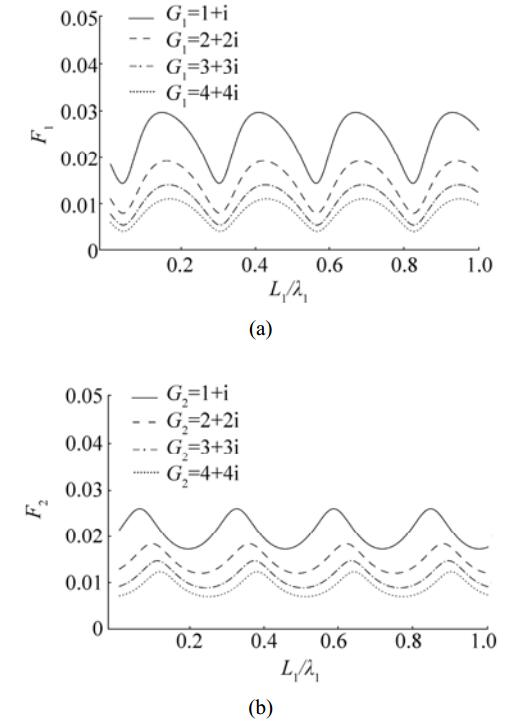
Figs. 12(a, b) show the variations of horizontal wave forces acting on the barriers versus the non-dimensional distance L1/λ1 between the barriers for different values of porous-effect parameters. Wave forces on the barrier change in an oscillatory manner with an increase in the gap between the barriers. Moreover, with an increase in the absolute values of porous-effect parameters, wave forces on the barrier decrease due to the increase in wave energy dissipation and transmission of more energy through the porous structures. A comparison with Fig. 11 reveals that maxima in wave force on the porous barriers is associated with minima in wave forces on the rigid wall and vice versa. Further, a comparison with Fig. 7 depicts that maximum wave reflection by the barrier is associated with maximum wave forces on the barriers. Thus, by suitable positioning of the barriers between the wall the undulated bottom, wave load on the wall can be reduced and a tranquility zone can be created.
|
Figure 12 (a) Variations of force F1 on the first barrier versus L1/λ1 for different values of G1 with G2=1+i and (b) variations of force F2 on the second barrier versus L1/λ1 for different values of G2 with G1=1+i, whilst h2/h1=0.25, θ=30º, L/λ1=0.4, L2/λ1=0.4, L3/λ1=1 |
Surface wave elevation in non-dimensional form Re{η}/A0 is plotted in Fig. 13 versus horizontal length x/λ1 for different values of porous effect parameter G. In general for smaller values of the complex porous-effect parameter |G|, amplitude in free surface elevation is less which is due to dissipation of a major part of the incident wave energy by the porous barriers. Further, certain increase in wave amplitude is observed in the undulated bed region compared to the open water region due to decrease in water depth. Moreover, for moderate value of the complex porous-effect parameter |G| wave amplitude in the confined zones between the barriers, and the second barrier and the rigid wall are smaller than that of the open water region. On the other hand, wave amplitude is high in wave trapping zones for higher values of the complex porous-effect parameter |G| which is due to more transmission through the porous barriers. Moreover, due to discontinuity in pressure on both sides of the porous barriers, certain discontinuity in surface wave elevation is observed across the porous barriers. Thus, Fig. 13 illustrates that more wave energy has been trapped for larger porosity of the barriers.
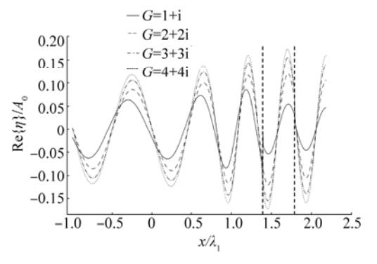
|
Figure 13 Variations of surface elevation Re{η}/A0 versus x/λ1 for different values of G(G1=G2=G) with h2/h1=0.25, θ=0º, L3/λ1=1, L/λ1=L1/λ1=L2/λ1=0.4 and α=0 |
Fig. 14 shows the free surface elevation against horizontal length x/λ1 for different values of incident wave angle θ for G1=G2=1+i. The general pattern in wave amplitude is similar to that observed in Fig. 13. However, for large values of incident angle wave amplitude is less within the confined zones than that in the open water regions due to loss of energy by the porous structures.

|
Figure 14 Variations of surface elevation Re{η}/A0 versus x/λ1 for different values of θ with h2/h1=0.25, G1=G2=1+i, L3/λ1=1, L/λ1=L1/λ1=L2/λ1=0.4 and α=0 |
In the present manuscript, oblique wave trapping by dual porous barriers located near a rigid wall is studied in the presence of undulated bottom bed of varied configurations. The mathematical boundary value problem is handled for solution using the eigenfunction expansion method for the uniform bed region and modified mild-slope approximation for the undulated bed region. For understanding the effectiveness of dual porous barriers and steps of varied configurations in creating an effective wave trapping system, the reflection coefficient, free surface elevation, and wave load on porous barriers and rigid wall are computed and analyzed for various wave and structural parameters. The study reveals that wave reflection increases with an increase in the variation in water depth as the wave propagate from deep water region to shallower depth. Further, wave reflection vary significantly due to change in bottom profile for smaller horizontal length of bottom undulation. For oblique incident waves, reflection is less compared to that of the normalized incident wave and there is a significant reduction in wave reflection due to the presence of dual porous barriers. Moreover, in the presence of dual barriers, minimum wave reflection can occur for two different angles of incidence and one of the minima will be diminishing for higher porosity. It is observed that for moderate structural porosity, by adjusting the gap between the dual porous barriers and gap between the barrier and the rigid wall, an efficient wave trapping system can be developed which will exert negligible wave force on the rigid porous barriers and the rigid wall. The concept and methodology can be extended to analyze wave scattering/trapping by an array of porous barriers having bottom undulation and the study will be of immense support to marine scientists/engineers engaged in the design of coastal structures for shore protection and creation of tranquility zones in marine environment in an effective manner.
AcknowledgementThe authors thank the reviewers for their valuable comments which have improved the presentation of this paper. Manisha expresses her gratitude to CTS, IIT Kharagpur for giving support under visitors program during which the revised manuscript was finalized.
Behera H, Kaligatla RB, Sahoo T. Wave trapping by porous barrier in the presence of step type bottom[J]. Wave Motion, 2015, 57: 219-230. DOI:10.1016/j.wavemoti.2015.04.005 ( 0) 0)
|
Behera H, Sahoo T, Ng Chiu-On. Wave scattering by a partial flexible porous barrier in the presence of a step-type bottom topography[J]. Coastal Engineering Journal, 2016, 58(3): 1650008. DOI:10.1142/S057856341650008X ( 0) 0)
|
Bennetts LG, Biggs NRT, Porter D. The interaction of flexural-gravity waves with periodic geometries[J]. Wave Motion, 2009, 46(1): 57-73. DOI:10.1016/j.wavemoti.2008.08.002 ( 0) 0)
|
Berkhoff JCW, 1972. Computation of combined refractiondiffraction. Proceedings of 13th International Conference on Coastal Engineering ASCE, Vancouver, Canada, 471-490. DOI: 10.1061/9780872620490.027 http://cedb.asce.org/cgi/WWWdisplay.cgi?19839
( 0) 0)
|
Bhattacharjee J, Guedes Soares C. Oblique wave interaction with a floating structure near a wall with stepped bottom[J]. Ocean Engineering, 2011, 38: 1528-1544. DOI:10.1016/j.oceaneng.2011.07.011 ( 0) 0)
|
Billingham J, King AC. Wave Motion[M]. Cambridge, United Kingdom: Cambridge University Press, 2000. DOI:10.1017/CBO9780511841033
( 0) 0)
|
Cerrato A, Gonzalez JA, Rodriguez-Tembleque L. Boundary element formulation of the mild-slope equation for harmonic water waves propagating over unidirectional variable bathymetries[J]. Engineering Analysis with Boundary Elements, 2016, 62: 22-34. DOI:10.1016/j.enganabound.2015.09.006 ( 0) 0)
|
Chamberlain PG, Porter D. The modified mild-slope equation[J]. Journal of Fluid Mechanics, 1995, 291: 393-407. DOI:10.1017/S0022112095002758 ( 0) 0)
|
Chwang AT. A porous-wavemaker theory[J]. Journal of Fluid Mechanics, 1983, 132: 395-406. DOI:10.1017/S0022112083001676 ( 0) 0)
|
Chwang AT, Chan AT. Interaction between porous media and wave motion[J]. Annual Review of Fluid Mechanics, 1998, 30: 53-84. DOI:10.1146/annurev.fluid.30.1.53 ( 0) 0)
|
Das S, Bora SN. Damping of oblique ocean waves by a vertical porous structure placed on a multi-step bottom[J]. Journal of Marine Science and Application, 2014, 13(4): 362-376. DOI:10.1007/s11804-014-1281-7 ( 0) 0)
|
Davies AG, Heathershaw AD. Surface-wave propagation over sinusoidally varying topography[J]. Journal of Fluid Mechanics, 1984, 144: 419-443. DOI:10.1017/S0022112084001671 ( 0) 0)
|
Dhillon H, Banerjea S, Mandal BN. Water wave scattering by a finite dock over a step-type bottom topography[J]. Ocean Engineering, 2016, 113: 1-10. DOI:10.1016/j.oceaneng.2015.12.017 ( 0) 0)
|
Huang Z, Li Y, Liu Y. Hydraulic performance and wave loadings of perforated/slotted coastal structures:A review[J]. Ocean Engineering, 2011, 38(10): 1031-1053. DOI:10.1016/j.oceaneng.2011.03.002 ( 0) 0)
|
Kaligatla RB, Manam SR. Bragg resonance of membranecoupled gravity waves over a porous bottom[J]. International Journal of Advances in Engineering Sciences and Applied Mathematics, 2016, 8: 222-237. DOI:10.1007/s12572-016-0169-y ( 0) 0)
|
Karmakar D, Bhattacharjee J, Guedes Soares C. Scattering of gravity waves by multiple surface-piercing floating membrane[J]. Applied Ocean Research, 2013, 39: 40-52. DOI:10.1016/j.apor.2012.10.001 ( 0) 0)
|
Karmakar D, Guedes Soares C. Wave transformation due to multiple bottom-standing porous barriers[J]. Ocean Engineering, 2014, 80: 50-63. DOI:10.1016/j.oceaneng.2014.01.012 ( 0) 0)
|
Koley S, Behera H, Sahoo T. Oblique wave trapping by porous structures near a wall[J]. Journal of Engineering Mechanics, 2014, 141(3): 1-15. ( 0) 0)
|
Li YC, Liu Y, Teng B. Porous effect parameter of thin permeable plates[J]. Coastal Engineering Journal, 2006, 48(4): 309-336. DOI:10.1142/S0578563406001441 ( 0) 0)
|
Liu Y, Li Y. Wave interaction with a wave absorbing double curtain-wall breakwater[J]. Ocean Engineering, 2011, 38(10): 1237-1245. DOI:10.1016/j.oceaneng.2011.05.009 ( 0) 0)
|
Manam SR, Kaligatla RB. A mild-slope model for membrane-coupled gravity waves[J]. Journal of Fluids and Structures, 2012, 30: 173-187. DOI:10.1016/j.jfluidstructs.2012.01.003 ( 0) 0)
|
Mandal S, Behera H, Sahoo T. Oblique wave interaction with porous, flexible barriers in a two-layer fluid[J]. Journal of Engineering Mathematics, 2015, 100(1): 1-31. DOI:10.1007/s10665-015-9830-x ( 0) 0)
|
Massel SR. Extended refraction-diffraction equation for surface waves[J]. Coastal Engineering, 1993, 19(1): 97-126. DOI:10.1016/0378-3839(93)90020-9 ( 0) 0)
|
Michael I, Sundarlingam P, Gang Y. Wave interactions with vertical slotted barrier[J]. Journal of Waterway, Port, Coastal, and Ocean Engineering, 1998, 124(3): 118-126. DOI:10.1061/(ASCE)0733-950X ( 0) 0)
|
Mondal A, Gayen R. Wave interaction with dual circular porous plates[J]. Journal of Marine Science and Application, 2015, 14(4): 366-375. DOI:10.1007/s11804-015-1325-7 ( 0) 0)
|
Porter D. The mild-slope equations[J]. Journal of Fluid Mechanics, 2003, 494: 51-63. DOI:10.1017/S0022112003005846 ( 0) 0)
|
Porter D, Porter R. Approximations to wave scattering by an ice sheet of variable thickness over undulating bed topography[J]. Journal Fluid Mechanics, 2004, 509: 145-179. DOI:10.1017/S0022112004009267 ( 0) 0)
|
Porter D, Staziker DJ. Extensions of the mild-slope equation[J]. Journal of Fluid Mechanics, 1995, 300: 367-382. DOI:10.1017/S0022112095003727 ( 0) 0)
|
Porter R, Porter D. Water wave scattering by a step of arbitrary profile[J]. Journal of Fluid Mechanics, 2000, 411: 131-164. DOI:10.1017/S0022112099008101 ( 0) 0)
|
Sahoo T, Chan AT, Chwang AT. Scattering of oblique surface waves by permeable barriers[J]. Journal of Waterway, Port, Coastal, and Ocean Engineering, 2000a, 126(4): 196-205. DOI:10.1061/(ASCE)0733-950X ( 0) 0)
|
Sahoo T, Lee MM, Chwang AT. Trapping and generation of waves by vertical porous structures[J]. Journal of Engineering Mechanics, 2000b, 126(10): 1074-1082. DOI:10.1061/(ASCE)0733-9399 ( 0) 0)
|
Smith R, Sprinks T. Scattering of surface waves by a conical island[J]. Journal of Fluid Mechanics, 1975, 72(2): 373-384. DOI:10.1017/S0022112075003424 ( 0) 0)
|
Suh KD, Kim YW, Ji CH. An empirical formula for friction coefficient of a perforated wall with vertical slits[J]. Coastal Engineering, 2011, 58(1): 85-93. DOI:10.1016/j.coastaleng.2010.08.006 ( 0) 0)
|
Suh KD, Park WS. Wave reflection from perforated-wall caisson breakwaters[J]. Coastal Engineering, 1995, 26(3): 177-193. DOI:10.1016/0378-3839(95)00027-5 ( 0) 0)
|
Twu SW, Lin DT. Wave reflection by a number of thin porous plates fixed in a semi-infinitely long flume[J]. Coastal Engineering Proceedings, 1990: 1046-1059. DOI:10.1061/9780872627765.081 ( 0) 0)
|
Yu X. Diffraction of water waves by porous breakwaters[J]. Journal of Waterway, Port, Coastal, and Ocean Engineering, 1995, 121(6): 275-282. DOI:10.1061/(ASCE)0733-950X(1995)121:6(275) ( 0) 0)
|
 2017, Vol. 16


