2. Department of Civil Engineering, University of Djillali Liabes, Sidi Bél-Abbés 22000, Algeria
Breakwaters are important costal structures used to prevent the passage of incident waves and currents; their primary function is to reduce wave transmission to protect shores and create calmer areas, such as in ports and marinas, for the safer operation of maritime transport.
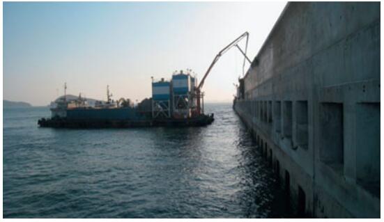
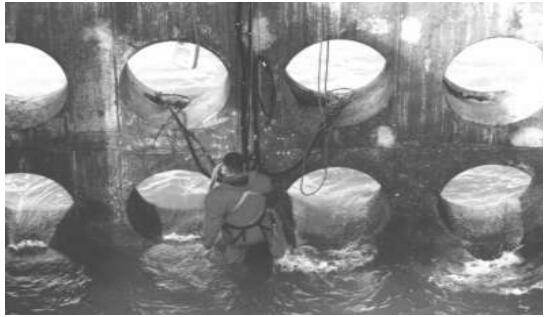
Perforated vertical barriers are sometimes used as breakwaters in special cases. The porosity provided by perforations enhances wave dissipation and, hence, reduces wave reflection and transmission. At the same time, the exchange of waters between the sea and shore sides of the perforated walls is not completely inhibited. Barriers perforations are usually made by leaving out square or circular openings in the walls as respectively shown in Figs. 1 and 2.
|
Figure 1 Perforated wall breakwater of the Dalian Chemical Production Terminal, China, in Huang et al. (2011) |
|
Figure 2 Perforated wall breakwater of Dieppe, France, in Bélorgey et al. (2003) |
Over the last three decades, a tremendous amount of research, both experimental and theoretical, has been dedicated to the study of barriers as breakwaters for perpendicular wave incidences. A highly useful review on the subject was given by Huang et al. (2011). Most of the works referred to in this work were carried out to achieve a reduction in wave reflections and transmissions primarily, and structure stability at the same time. Numerical methods have helped in the validation work and the setting up of simple analytical tools for quick evaluations. These methods are now well established and used with confidence to analyze a variety of breakwater configurations.
For normal wave incidence, Hagiwara (1984) developed analytical solutions of the reflection and transmission coefficients based on an integral equation upon single-and double-porous walls; the results of this study compared well with experimental measurements. Isaacson et al. (1999) studied the interaction of normal waves with a pair of slotted barriers using an eigenfunction expansion method and compared results with experimental measurements. The authors found results that were in generally satisfactory agreement provided that the relevant empirical coefficients representing the energy dissipation were suitably chosen. Huang (2007) estimated the reflection and transmission coefficients of single-and double-slotted thin walls using simple algebraic expressions with reasonable accuracy.
To assess the hydrodynamic performance of a surface piercing wave absorbing double curtain-wall breakwater with a porous front wall and an impermeable back wall, Liu and Li (2011) developed an analytical solution based on the eigenfunction expansion and least-squares methods; they then showed that, with appropriate structure parameters, both the reflection and transmission coefficients of the breakwater may be maintained below 0.5 over a wide range of relative water depths. Liu et al. (2014) employed the eigenfunction expansion method to investigate the wave motion over a submerged Jarlan-type breakwater consisting of a perforated front wall and a solid rear wall and compared results with experimental measurements; these scholars showed that interchanging the front and rear walls exerts no effects on the transmission coefficient, but that adopting a seaside perforated wall would result in a smaller reflection coefficient.
In comparison with porous barriers, which have been extensively investigated experimentally for perpendicular wave attacks, oblique waves have been considered less because of several important experimental shortcomings. Investigating oblique waves in wave flumes is nearly impossible due to reflections arising from the side walls. Thus, unless the waves are damped on the flume side to prevent the occurrence of these added reflections, one cannot carry out such investigations.
The effects of oblique wave attacks are often assumed to be less extensive than those induced by perpendicular wave attacks. This assumption, however, seems to be very conservative. Experimental works on porous barriers with oblique waves are fairly scarce due to the problems described previously. The only works we found in the literature that are related to this subject are those of Ijima et al. (1978) and Li et al. (2002).
Theoretical works on the interaction of oblique waves and barriers (single and double walls) are widely available in the literature. On the basis of integral equations and the Galerkin method, Porter (1995) and Porter and Evans (1995) developed accurate solutions of the scattering of normal and obliquely incident waves by single and double impermeable vertical barriers with gaps. Using the same method, Das et al. (1997) investigated oblique water wave diffraction by two equally thin, parallel, fixed impermeable vertical barriers with gaps present in uniform water depth. The authors found that waves are better reflected by a double barrier system than by a single barrier.
Suh and Park (1995) developed an analytical model based on the Galerkin eigenfunction method to investigate the performance of a perforated wall caisson in oblique waves and then compared their numerical results with the experimental measurements of Ijima et al. (1978), who experimentally studied the interaction of oblique waves with a similar type of breakwater in a wave basin for three incident wave angles (40°, 50°, and 60°). Overall, the agreement between the measurements and calculations was acceptable. A similar study was undertaken both analytically and experimentally for three incident wave angles (0°, 22.5°, and 45°) by Li et al. (2002), who found good agreement between the experimental data and analytical results once more. Teng et al. (2004) employed the eigenfunction expansion method to study the interaction of obliquely incident waves with an infinite number of perforated caissons and found that the reflection coefficients of obliquely incident waves are smaller when the length of caissons is shorter at a low frequency.
Using the same method, Liu et al. (2007) examined the reflection of obliquely incident waves by an infinite array of partially perforated caissons and discussed the effects of a number of parameters in detail. This type of breakwater was found to be more efficient than the caisson breakwater with a fully perforated front wall. Liu et al. (2012) extended the work of Teng et al. (2004) for an infinite array of multi-chamber perforated caissons. Liu et al. (2009) examined the interaction of oblique waves with a perforated front wall breakwater partially filled with rocks in its wave chamber by means of the matched eigenfunction expansion method and found that increasing the thickness of the rock fill will generally increase the refection coefficient. However, increasing the incident angle of the wave causes the reflection coefficient of the breakwater to first decrease, reaching a minimum value, and then increase monotonously. Liu and Li (2010) developed analytical solutions based on the eigenfunction expansion and least-squares methods to examine the interaction of oblique waves with a partially immersed wave absorbing breakwater consisting of a perforated front barrier and a solid rear barrier. The absorptive performance of the breakwater was found to be sensitive to the relative space between the two barriers, the angle of incident waves, the relative draft of the breakwater, and the porosity of the front barrier.
Other researchers included the effects of the seabed configuration, structural rigidity, and even two later fluids in their investigations. Behera et al. (2015a) developed a semi-analytical solution based on the eigenfunction expansion method for oblique waves trapped by a rigid porous barrier near a rigid wall in the presence of varied configurations. The authors found that, compared with a flat bed, reflections show trends depending on the type of bed configuration applied. Using the eigenfunction expansion method and the Multi-Domain Boundary Element Method (MDBEM) separately, Koley et al. (2015) studied oblique wave trapping by bottom-standing and surface-piercing porous structures in front of a vertical rigid wall. Behera et al. (2015b) extended this study for scattering and trapping in two layer fluids. In wave trapping, a surface-piercing porous structure will always act as a better wave-trapping system than a bottom-standing structure regardless of the wave incidence angle. In oblique wave scattering, zero wave reflection can be achieved by a partial porous structure at moderate angles of incidence.
Yueh and Chuang (2012) applied MDBEM to investigate the performance of a vertical porous plate with a single degree of freedom in front of a solid wall and in normal waves. These authors found that the minimum reflection is increased as the system becomes less stiff, and that the system would behave exactly in the same manner as the caisson type breakwater with a rigid porous wall in front when the stiffness is increased beyond a certain value. Similar conclusions were made by Kaligatla et al. (2015), who studied the trapping of oblique surface gravity waves by a vertical submerged flexible porous thin plate located near a rigid wall using integral equations. Mandal et al. (2016) studied oblique wave scattering using multiple porous and flexible surface-piercing and bottom-standing partial barriers in a two-layer fluid and found that both structural flexibility and a moderate choice of porosity could dissipate the maximum wave energy and create an effective protection system.
In this work, the interaction of oblique regular waves with a surface piercing breakwater of double vertical porous thin walls is studied. Specifically, the effects of the leeward side porous wall are examined. A multi-domain boundary element method is developed for the present analysis.
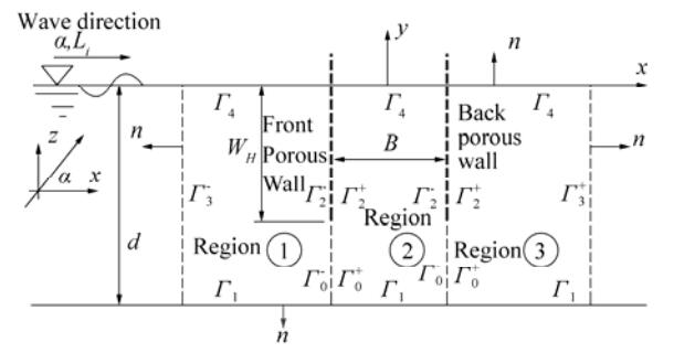
2 Theoretical formulation 2.1 Governing equations and boundary conditionsThe idealized geometry of the three-dimensional problem is shown in Fig. 3. Regular waves of small amplitude a, period T, and wavelength Li impinge from the left at an angle α with respect to the direction of the axis x in water of depth d. Assuming an irrotational flow and incompressible fluid motion, the problem is formulated using a velocity potential
|
Figure 3 Problem definitions for a breakwater system of double porous walls of height WH |
| $ {\Phi (x, {\rm{ }}y, {\rm{ }}z, t){\rm{ = Re[ }}\varphi {\rm{ }}(x, {\rm{ }}y) \cdot {{\rm{e}}^{{\rm{i(}}{k_z}z{\rm{ - }}\omega t{\rm{)}}}}{\rm{ ]}}} $ |
where Re denotes the real component,
We consider a pair of porous walls of height WH separated by a distance B (width of the absorbing chamber) and extending from above the water surface to a certain distance above the channel floor. With this disposition, the total fluid domain is divided in three regions: region 1 is in front of the left wall (seaward side), region 3 is behind the right wall (leeward side), and region 2 is between both walls. With sufficient wall porosity, waves are transmitted to the leeward side. The flow in each region could still be described by a velocity potential because of the assumptions of linear wave theory. Special matching conditions at the interfaces of the flow regions ensure the smooth transfer of mass flow from one region to the next. Note that at this stage in this study, the perforated walls are treated as solid homogeneous porous materials.
The spatial velocity potential in each region (j) satisfies the following boundary conditions:
| $ \left. \begin{array}{l} {\frac{{{\partial ^{\rm{2}}}{\varphi ^{{\rm{(}}j{\rm{)}}}}}}{{\partial {x^{\rm{2}}}}} + {\rm{ }}\frac{{{\partial ^{\rm{2}}}{\varphi ^{{\rm{(}}j{\rm{)}}}}}}{{\partial {y^{\rm{2}}}}} - k_z^2.{\varphi ^{{\rm{(}}j{\rm{)}}}}{\rm{ = 0 }}\;j = {\rm{1, 2, 3 }}}\\ {\rm{ (fluid\;region) }} \end{array} \right\} $ | (1) |
| $ \left. \begin{array}{l} {\frac{{\partial {\varphi ^{{\rm{(}}j{\rm{)}}}}}}{{\partial n}} - \frac{{\mathop \omega \nolimits^2 }}{g} \cdot {\varphi ^{{\rm{(}}j{\rm{)}}}}{\rm{ = 0 }}}\;\;\;j = {\rm{1, 2, 3 \;and \;}}y = {\rm{0 }}\\ {\rm{ (free\;surface\;boundary }}\;\;{\mathit{\Gamma} _4}{\rm{)}} \end{array} \right\} $ | (2) |
| $ \left. \begin{array}{l} {\frac{{\partial {\varphi ^{{\rm{(}}j{\rm{)}}}}}}{{\partial n}}{\rm{ = 0 }}\;\;\;j = {\rm{1, 2, 3 \;and \; }}y = - d}{\rm{ }}\\ {\rm{ (seabed \;boundary }}\;{\mathit{\Gamma} _1}{\rm{)}} \end{array} \right\} $ | (3) |
| $ \left. \begin{array}{l} {\frac{{\partial \left({{\varphi ^{(j)}} - \mathop \varphi \nolimits_I } \right)}}{{\partial n}} + {\rm{i}} \cdot {k_x} \cdot \left({{\varphi ^{(j)}} - \mathop \varphi \nolimits_I } \right){\rm{ = 0 }}\;\;j = {\rm{1}}}{\rm{ }}\\ {\rm{ (radiation \; condition \;at }}\;x{\rm{ }} \to {\rm{ }} - {\rm{ }}\infty {\rm{) }}\\ {\frac{{\partial \left({{\varphi ^{(j)}}} \right)}}{{\partial n}} - {\rm{i}} \cdot {k_x} \cdot \left({{\varphi ^{{\rm{(}}j{\rm{)}}}}} \right){\rm{ = 0 }}\;\;\;j = {\rm{3 }}}{\rm{ }}\\ {\rm{ (radiation \;condition \;at }}\;x{\rm{ }} \to {\rm{ }} + {\rm{ }}\infty {\rm{) }} \end{array} \right\} $ | (4) |
where g is the gravitational acceleration, n is the normal to the boundary pointing out of a flow region, and
At the interfaces of flow regions (1) and (2) and flow regions (2) and (3), special matching conditions are imposed. Along the fictitious boundaries
| $ \left. \begin{array}{l} {\varphi ^{{\rm{(1)}}}} = {\varphi ^{{\rm{(2)}}}}\;\;{\rm{ and }}\;\;\frac{{\partial {\varphi ^{{\rm{(1)}}}}}}{{\partial n}}{\rm{ = }} - \frac{{\partial {\varphi ^{{\rm{(2)}}}}}}{{\partial n}}{\rm{ }}\\ {\rm{ for }}\;x = - B{\rm{/2 \;\;and \;\; - }}d{\rm{ }} \le y \le - {W_H}\\ {\varphi ^{{\rm{(2)}}}} = {\varphi ^{{\rm{(3)}}}}{\rm{ \;\; and \;\; }}\frac{{\partial {\varphi ^{{\rm{(2)}}}}}}{{\partial n}}{\rm{ = }} - \frac{{\partial {\varphi ^{{\rm{(3)}}}}}}{{\partial n}}{\rm{ }}\\ {\rm{ for }}\;x = + B{\rm{/2 \;\;and\;\; }} - d{\rm{ }} \le y \le - {W_H} \end{array} \right\} $ | (5) |
For the porous walls (boundaries
| $ \left. \begin{array}{l} \frac{{\partial {\varphi ^{{\rm{(1)}}}}}}{{\partial n}}{\rm{ = }} - \frac{{\partial {\varphi ^{{\rm{(2)}}}}}}{{\partial n}}{\rm{ = i}}k{G_1}{\rm{(}}{\varphi ^{{\rm{(1)}}}} - {\varphi ^{{\rm{(2)}}}}{\rm{) }}\\ {\rm{ for }}\;\;x = - B{\rm{/2 \;\;and\;\; }} - {W_H} \le y \le 0\\ \frac{{\partial {\varphi ^{{\rm{(2)}}}}}}{{\partial n}}{\rm{ = }} - \frac{{\partial {\varphi ^{{\rm{(3)}}}}}}{{\partial n}}{\rm{ = i}}k{G_2}{\rm{(}}{\varphi ^{{\rm{(2)}}}} - {\varphi ^{{\rm{(3)}}}}{\rm{) }}\\ {\rm{ for }}\;\;x = + B{\rm{/2 \;\;and \;\; }} - {W_H} \le y \le 0 \end{array} \right\} $ | (6) |
G is a dimensionless complex quantity, and the subscripts 1 and 2 refer to the front and back walls, respectively. This quantity is known as the porous effect parameter and can be evaluated by different methods (Huang, 2011). The method of Yu (1995) is adopted in this study for its simplicity:
| $ G = {\rm{ }}\frac{P}{{k \cdot \delta \cdot {\rm{(}}f - {\rm{i}}{\rm{.}}s{\rm{)}}}} = \left| G \right| \cdot {{\rm{e}}^{{\rm{i}} \cdot \theta }}\;\;\;\;{\rm{ for \;0}} \le \theta \le {\rm{\pi /2}} $ | (7) |
where δ is the thickness of the wall, f is the linearized resistance coefficient,
To solve the problem, the radiation condition of Eq. (4) is treated by truncating regions (1) and (3) at two fictitious vertical boundaries with distances of x = –l (boundary
| $ \left. \begin{array}{l} {\varphi ^{(1)}}{\rm{ = }}\left({{{\rm{e}}^{{\rm{i}}{k_x} \cdot {\rm{(}}x + l{\rm{)}}}} + {R_{\rm{0}}}{{\rm{e}}^{ - {\rm{i}}{k_x}{\rm{(}}x + l{\rm{)}}}}} \right){I_{\rm{0}}}(y){\rm{ ; }}\frac{{\partial {\rm{ }}{\varphi ^{(1)}}}}{{\partial {\rm{ }}n}}{\rm{ = }} - \frac{{\partial {\rm{ }}{\varphi ^{(1)}}}}{{\partial {\rm{ }}x}}\\ {\rm{ for}}\;\; x = - l{\rm{ (boundary }}\;\;\mathit{\Gamma} _{\rm{3}}^{\rm{ - }}{\rm{)}}\\ {\varphi ^{(3)}}{\rm{ = }}\left({{T_{\rm{0}}}{{\rm{e}}^{{\rm{i}}{k_x}{\rm{(}}x - l{\rm{)}}}}} \right){I_{\rm{0}}}(y){\rm{ ; }}\frac{{\partial {\rm{ }}{\varphi ^{(3)}}}}{{\partial {\rm{ }}n}}{\rm{ = }}\frac{{\partial {\rm{ }}{\varphi ^{(3)}}}}{{\partial {\rm{ }}x}}\\ {\rm{ for}}\;\; x = {\rm{ }} + l{\rm{ (boundary }}\;\;\mathit{\Gamma} _{\rm{3}}^ + {\rm{)}} \end{array} \right\} $ | (8) |
where
The physical problem described previously by Eq. (1) and the boundary conditions given by Eqs. (2), (3), (5), (6), and (8) present a boundary value problem that is first transformed into integral equations using Green's theorem and then solved by MDBEM. For smooth (constant) elements, the general form of the integral equation is written as:
| $ \left. \begin{array}{l} {\frac{1}{2}\varphi _i^j{\rm{(x, y)}} + \mathop \smallint \limits_{{\mathit{\Gamma} ^j}} \left({\frac{{\partial Q}}{{\partial n}}{\varphi ^j}{\rm{(}}x{\rm{', }}y{\rm{')}} - Q\frac{{\partial {\varphi ^j}{\rm{(}}x{\rm{', }}y{\rm{')}}}}{{\partial n}}} \right){\rm d}\mathit{\Gamma} = 0}\\ {\rm{ (for \; region }}\;j = {\rm{1, 2, 3)}} \end{array} \right\} $ | (9) |
This equation relates the potentials
| $ {Q = - \frac{1}{{2{\rm{\pi }}}}{K_{\rm{0}}}({k_z}.r) {\rm{; }} \frac{{\partial Q}}{{\partial n}} = \frac{{\partial Q}}{{\partial r}} \cdot \frac{{\partial r}}{{\partial n}} = {{\frac{{\mathop k\nolimits_z }}{{2{\rm{\pi }}}}}{K_{\rm{1}}}({k_z}.r)}} \cdot \frac{{\partial r}}{{\partial n}} $ | (10) |
K0 and K1 are the respective zeroth and first orders of the modified Bessel functions of the second kind. The quantity
| $ {{K_{\rm{0}}}({k_z} \cdot r) = - 0.5772 - \ln ({k_z} \cdot r/2)} $ |
Eq. (9) is applied consecutively to all source points in each fluid region (j). To implement MDBEM numerically, the total boundary Γj of each region is discretized into a number of Nj elements (N1, N2, N3, corresponding to the numbers of element-nodes for regions 1, 2, and 3, respectively). The variations of the variables over the elements are assumed to be constant, and the unknowns are defined at the mid-element nodes. The resulting discretized integral equations are written in the following general discrete forms:
| $ \left. \begin{align} &\sum\limits_{i=\text{1}}^{{{N}^{j}}}{\sum\limits_{m=\text{1}}^{{{N}^{j}}}{\text{ }\left[ \underset{\mathit{\Delta} {{\mathit{\Gamma} }_{m}}}{\mathop \int }\, \left(\frac{\partial Q}{\partial n}\mathop{\mathop{+\frac{{{\text{ }\!\!\delta\!\!\text{ }}_{im}}}{2}}_{}}_{} \right){\rm d}\mathit{\Gamma} \right]}\varphi _{m}^{j}}= \\ &\text{ }\sum\limits_{i=1}^{{{N}^{j}}}{\sum\limits_{m=1}^{{{N}^{j}}}{\text{ }\left[ \underset{\mathit{\Delta} {{\mathit{\Gamma} }_{m}}}{\mathop \int }\, Q\cdot {\rm d}\mathit{\Gamma} \right]}\mathop{\frac{\partial \varphi _{m}^{j}}{\partial n}\text{ }}_{}}\text{(for }j=\text{1, 2, 3)} \\ \end{align} \right\} $ | (11) |
where ΔΓm is the length of an element (m) of the boundary Γj and δim is the Kronecker delta. The discretized form of a region (j) can be rewritten in matrix form as:
| $ {\left[ {{\rm{ }}{{{\rm{\bar H}}}_{im}}^{{\rm{(}}j{\rm{)}}}} \right]_{{\rm{ }}{N^j}{\rm{x }}{N^j}}}{\rm{ }}.{\rm{ }}{\left\{ {{\rm{ }}\phi _m^j} \right\}_{{\rm{ }}{N^j}}} = {\left[ {{\rm{ }}{{{\rm{\bar G}}}_{im}}^{{\rm{(}}j{\rm{)}}}} \right]_{{\rm{ }}{N^j}{\rm{x }}{N^j}}}{\rm{ }}{\rm{. }}{\left\{ {\frac{{\partial \phi _m^j}}{{\partial n}}} \right\}_{{N^j}}}{\rm{ (}}j = {\rm{1, 2, 3)}} $ | (12) |
| $ \left. {{{\overline {\rm{H}} }_{im}} = {\rm{ }}\frac{{{{\rm{\delta }}_{im}}}}{2} + \mathop \smallint \limits_{\mathit{\Delta} {\mathit{\Gamma} _m}} \left({\frac{{\partial Q}}{{\partial n}}} \right).{\rm d}\mathit{\Gamma} \;\;{\rm{ and }}\;\;{{\overline {\rm{G}} }_{im}} = {\rm{ }}\mathop \smallint \limits_{\mathit{\Delta} {\mathit{\Gamma} _m}} Q.{\rm d}\mathit{\Gamma} } \right\} $ | (13) |
These coefficients relate a source point (i) to a field point (m) belonging to an element ΔΓm. The integrals in Eq. (13) are evaluated using Gaussian quadrature rules, and the discretized system in Eq. (13) is further expanded to include all flow regions (j = 1, 2, 3) in one system:
| $ \left. \begin{array}{l} {\rm{ }}{\left[ {\begin{array}{*{20}{c}} {}&{}&{}\\ {\left[ {{{{\rm{\bar H}}}^{{\rm{(1)}}}}} \right]}&{\rm{0}}&{\rm{0}}\\ {}&{}&{}\\ 0&{\left[ {{{{\rm{\bar H}}}^{{\rm{(2)}}}}{\rm{ }}} \right]}&{\rm{0}}\\ {}&{}&{}\\ 0&0&{\left[ {{\rm{ }}{{{\rm{\bar H}}}^{{\rm{(3)}}}}} \right]}\\ {}&{}&{} \end{array}} \right]_{N \times {\rm{ }}N}}{\rm{ }}.{\rm{ }}{\left\{ {\begin{array}{*{20}{c}} {\left\{ {{\rm{ }}{\varphi ^{(1)}}} \right\}}\\ \begin{array}{l} \\ \left\{ {{\rm{ }}{\varphi ^{(2)}}} \right\}\\ \end{array}\\ {\left\{ {{\rm{ }}{\varphi ^{(3)}}} \right\}} \end{array}} \right\}_N} = \\ {\rm{ }}{\left[ {\begin{array}{*{20}{c}} {}&{}&{}\\ {\left[ {{\rm{ }}{{{\rm{\bar G}}}^{{\rm{(1)}}}}} \right]}&0&0\\ {}&{}&{}\\ 0&{\left[ {{\rm{ }}{{{\rm{\bar G}}}^{{\rm{(2)}}}}} \right]}&0\\ {}&{}&{}\\ 0&0&{\left[ {{\rm{ }}{{{\rm{\bar G}}}^{{\rm{(3)}}}}} \right]}\\ {}&{}&{} \end{array}} \right]_{{\rm{ }}N \times N}}{\rm{ }}{\rm{. }}{\left\{ {\begin{array}{*{20}{c}} {\left\{ {\frac{{\partial {\varphi ^{(1)}}}}{{\partial {\rm{ }}n}}} \right\}}\\ {\left\{ {\frac{{\partial {\varphi ^{(2)}}}}{{\partial {\rm{ }}n}}} \right\}}\\ {\left\{ {\frac{{\partial {\varphi ^{(3)}}}}{{\partial {\rm{ }}n}}} \right\}} \end{array}} \right\}_N} \end{array} \right\} $ | (14) |
where N is the total number of constant elements from all flow regions, e.g.,
Finally, the boundary conditions, which are expressed by Eqs. (2), (3), (5), (6), and (8), are introduced to Eq. (14). The resulting algebraic system of equations is further rearranged such that all unknowns are moved to one side. The equation is then solved numerically using a Gaussian elimination algorithm to yield the vector of unknowns (diffracted velocity potentials ϕ (or
| $ \begin{matrix} C_r\text{= }\!\!|\!\!\text{ }{{R}_{\text{0}}}\text{ }\!\!|\!\!\;\;\;\text{ and }\;\;\;C_t\text{= }\!\!|\!\!\text{ }{{T}_{\text{0}}}\text{ }\!\!|\!\!\text{ } \\ \end{matrix} $ | (15) |
The wave energy loss coefficient Cd, which describes the portion of the incident wave energy dissipated by the perforated walls, is given by:
| $ C_d=1-{{(C_r)}^{2}}-{{(C_t)}^{2}} $ | (16) |
Fully extended porous walls are treated simply by setting WH = d. Single porous wall breakwaters are solved by setting the porosity of the front wall to be sufficiently large (G1 = ∞ or P1 = 1). This way, the front wall vanishes and the structure is reduced to a single porous wall of porosity P2 and porous parameter G2. In all subsequent computations, a large value of G1 = ∞ is taken as 108.
3 Validation of the numerical methodTo demonstrate the validity of the present method, the numerical results of the boundary element formulation for a number of limiting cases are compared against those of other investigators in normal (α = 0°) and oblique waves.
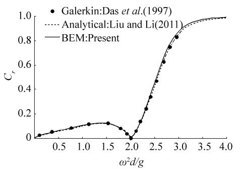
The first case examined is a structure of double partially immersed impermeable barriers (|G1| = |G2| = 0) separated by a distance B such that the relative wall depth WH/d = 0.2 and B/d = 0.6. This case was previously studied by Das et al. (1997) and Liu and Li (2011), who produced results of the reflection coefficients (Cr) of the structure. As shown in Fig. 4, the agreement among the results of the three methods is fairly high.
|
Figure 4 Comparison of Cr values obtained from different methods for double impermeable barriers (α = 0°, WH/d = 0.2, B/d = 0.6, and |G1| = |G2| = 0) |
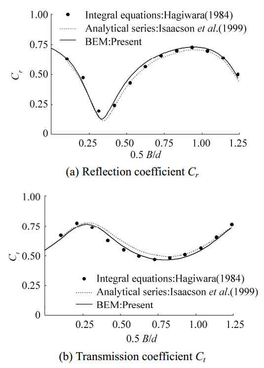
The second case examined is a structure of fully immersed double slotted barriers (WH/d = 1.0, d = 0.5 m, relative water depth kd = 1.5, and P1 = P2 = 15%); this case is identical to that studied by Hagiwara (1984) and Isaacson et al. (1999), who provided results of Cr and Ct. Fig. 5 shows variations in Cr and Ct versus the relative chamber width (0.5B/d). The results of the three methods are generally in close agreement. Note that for the BEM predictions, the values used for the linearized friction and added mass coefficients (f = 0.5 and Cm = 0.18) are identical to those reported by Isaacson et al. (1999) in their analytical investigation.
|
Figure 5 Variations in Cr and Ct as determined from different methods for double porous slotted barriers (α = 0°, WH/d = 1.0 with d = 0.5 m, kd = 1.5, P1 = P2 = 15%, f = 0.5, and Cm = 0.18) |
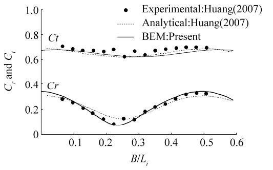
In the third example, the BEM predictions of the present method are compared with the experimental results of Huang (2007), who carried out tests on double slotted thin walls constructed of closely spaced rectangular cylinders of heights equal to a water depth d = 0.3 m (WH/d = 1) with wave period T = 1.1 s, and P1 = P2 = 21%. Huang (2007) also provided analytical expressions of the coefficients Cr and Ct, which were derived from linear wave theory. Variations in Cr and Ct versus the relative chamber width (B/Li) are shown in Fig. 6. The agreement among the BEM results, the experiments, and the analytical expressions is satisfactory. Note that in the BEM predictions, the estimated value of the linearized friction coefficient was f = 2.5 and the added mass coefficient was set to zero (Cm = 0).
|
Figure 6 Variations in Cr and Ct as determined from different methods for double porous slotted barriers (α = 0°, WH/d = 1 with d = 0.3 m, T = 1.1 s, P1 = P2 = 21%, f = 2.5, and Cm = 0) |
The results of Cr from the current numerical method are shown in Fig. 7 and compared with those of Das et al. (1997) and Liu and Li (2010) for a structure of double impermeable walls (|G1| = |G2| = 0) in oblique waves (α = 30°) with WH/d = 0.6 and B/d = 2. The results of the three methods are in close agreement, and the small differences generated in the BEM solutions could be attributed to the use of constant boundary elements.

|
Figure 7 Variations in Cr for double impermeable walls (α = 30°, WH/d = 0.6, B/d = 2, and |G1| = |G2| = 0) |
Due to the large number of parameters on hand, a very large number of cross-correlations must be investigated. The parameters of interest are P1 and P2 (or |G1| and |G2|, respectively), WH/d, kd, B/Li, and α. All of these parameters must be cross-correlated with care to reveal meaningful conclusions. In this work, only a subset of the data gathered from this study is shown.
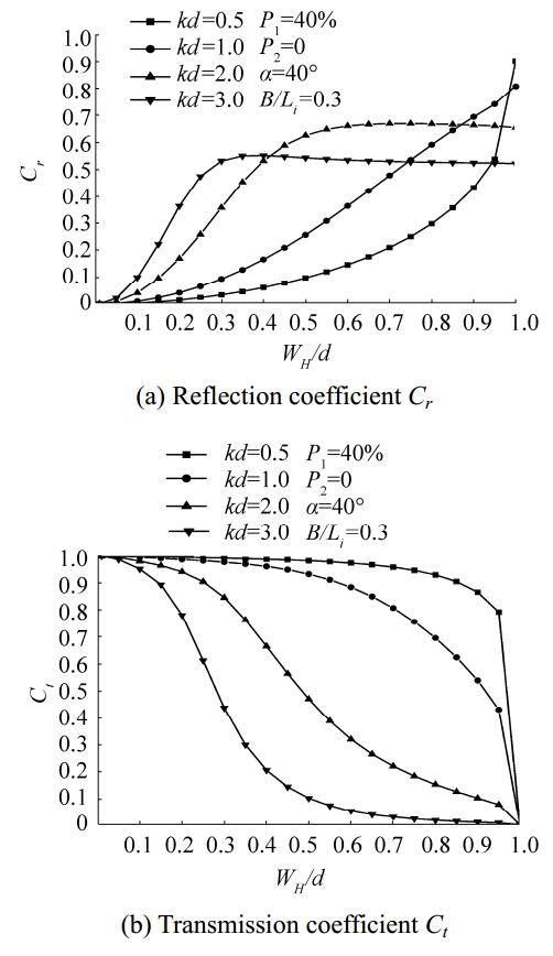
In Fig. 8, the values of Cr and Ct are shown versus WH/d for different values of kd; in this case, a breakwater with P1 = 40% and an impermeable back wall (P2 = 0%), α = 40°, and B/Li = 0.3 is analyzed. When the conditions approach those of shallow water (kd < 1), the walls must be fully extended to reflect more and transmit fewer waves. On the other hand, when the conditions approach those of deep water (kd > 2), extending the barriers beyond a certain limit results in no change to Cr but decreases Ct at a slower rate. When WH/d = 1, no wave transmission occurs (Ct = 0) since the back wall is impermeable. By contrast, wave reflection is full (Cr = 1) for smaller values of kd but decreases as kd is increased.
|
Figure 8 Variations in Cr and Ct versus WH/d for different values of kd |
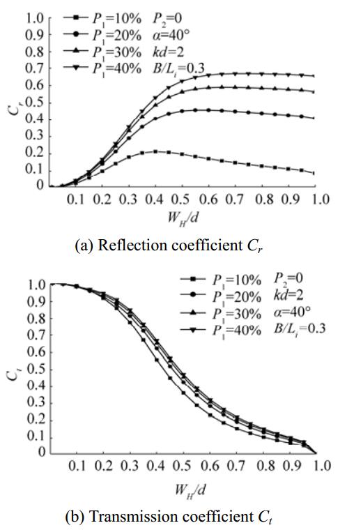
In Fig. 9, variations in Cr and Ctare shown versus WH/d for different values of P1, an impermeable back wall (P2 = 0%), α = 40°, B/Li = 0.3, and kd = 2. In this case, when the conditions approach those of deep water, both Cr and Ct decrease as P1 increases regardless of the water depth. The wave chamber apparently tends to dissipate more wave energy, leading to less reflection and wave transmission. When WH/d = 1, no waves are transmitted but the Cr values are clearly below 1, as demonstrated in Fig. 8. Regardless of the value of P1, transmission decreases but reflection does not show much variation for WH/d ≥ 0.5.
|
Figure 9 Variations in Cr and Ct versus WH/d for different values of P1 |
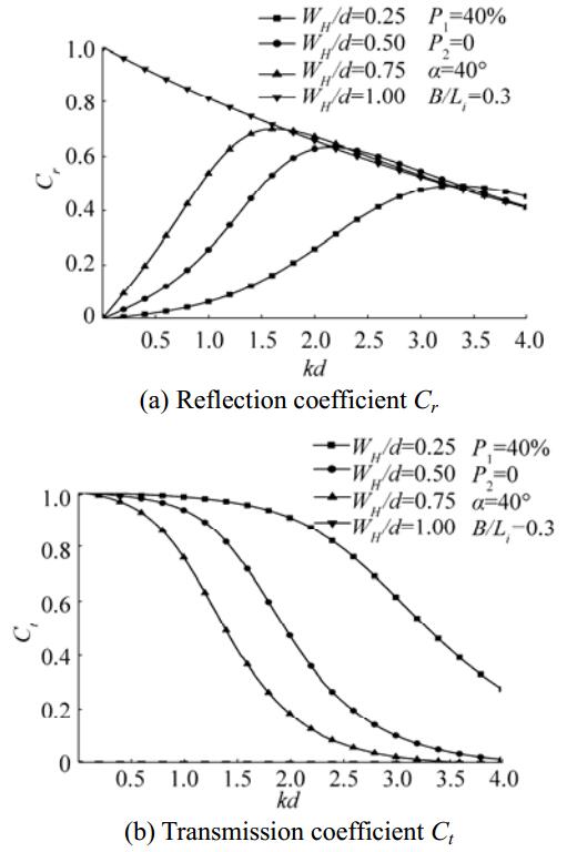
Fig. 10 illustrates variations in Cr and Ct versus kd for different values of WH/d, α = 40°, B/Li = 0.3, P1 = 40%, and P2 = 0%. The results show some interesting features. For fully extended walls (WH/d = 1), no transmitted waves are permitted since the back wall is impermeable. Full reflection occurs when kd tends to approach zero and decreases with increasing values of kd. For partially submerged surface piercing walls (WH/d < 1), all waves are transmitted and no reflection occurs when kd approaches zero. As kd increases, wave transmission decreases but reflection increases and then follows the curve observed for WH/d = 1.
|
Figure 10 Variations in Cr and Ct versus kd for different values of WH/d |
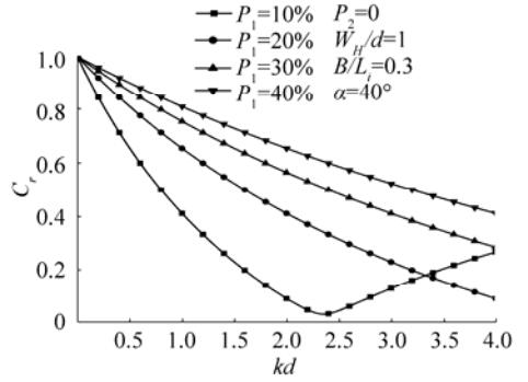
Variations in Cr versus kd for different P1 are shown in Fig. 11 for the previous case where the walls are fully extended to the seabed (WH/d= 1). Regardless of kd, Cr increases with increasing P1. However, regardless of P1, reflection tends to approach 1 in the limit kd = 0 and decreases for increasing values of kd. An exception occurs when P1 = 10%. In this case, Cr first decreases to a minimum at around kd = 2.4 and then increases once more. Thus, for an impermeable back wall, a front wall with 10% porosity leads to minimal reflection, especially for intermediate waters (1.5 < kd < 3.0).
|
Figure 11 Variations in Cr versus kd for different values of P1 |
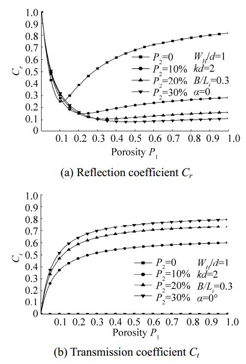
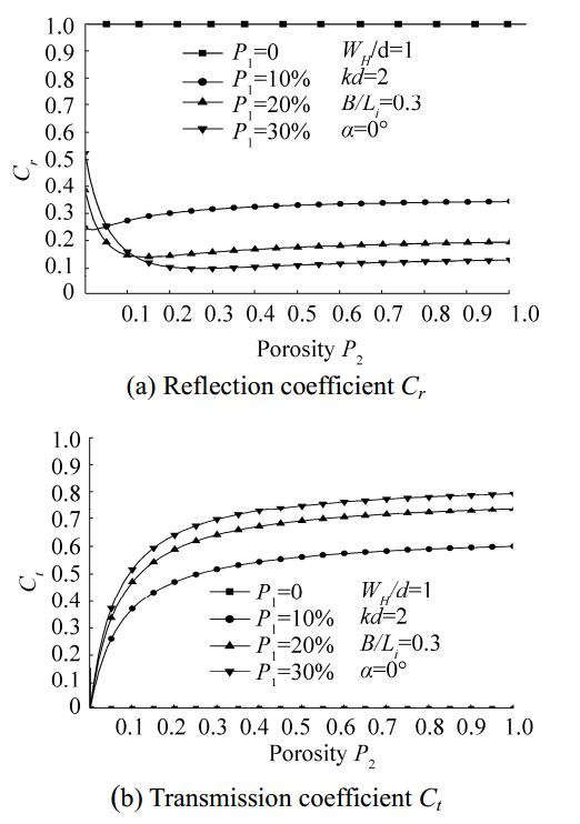
In Fig. 12, variations in Cr and Ct versus P1 for different values of P2 are illustrated for a breakwater extending to the seabed (WH/d = 1), α = 0°, kd = 2, and B/Li = 0.3. Whereas the Cr values decrease with increasing P2, the Ct values show the opposite trend. The best efficiency (minimum values of Cr and Ct) is achieved when the back wall is impermeable and P1 = 10%. Thus, to achieve the best dissipative system, the porosities of the walls ought to be kept below 40% with P1 about 10% higher than P2. Similar conclusions can be made from Fig. 13, which shows variations in Cr and Ct versus P2 for different values of P1.
|
Figure 12 Variations in Cr and Ct versus P1 for different values of P2 |
|
Figure 13 Variations in Cr and Ctversus P2 for different values of P1 |
In the following computations, the correlations are varied against different α for a breakwater system with B/Li= 0.3.
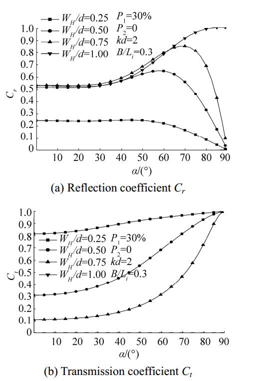
Fig. 14 illustrates the variations in Cr and Ct for different values of WH/d when P1 = 30%, P2 = 0%, and kd = 2. Cr clearly remains practically constant up to α = 40° and then increases or decreases depending on the value of WH/d. At α = 90°, Cr increases to 1 when WH/d = 1 and decreases to zero for other values of WH/d. Regardless of the value of α, Cr increases with increasing value of WH/d, especially when α > 40°. When α = 90°, Ct tends to approach 1 for all values of WH/d and then decreases sharply to zero at WH/d = 1.
|
Figure 14 Variations in Cr and Ct versus incident wave angles for different values of WH/d |
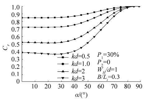
In Fig. 15, when WH/d = 1, Cr varies minimally and appears nearly constant for different values of kd at α up to 40°. All values of Cr converge to 1 at α = 90°, and no waves are transmitted since the back wall is impermeable. Regardless of the value of α, the Cr values decrease with increasing kd.
|
Figure 15 Variations in Cr versus incident wave angles for different values of kd |
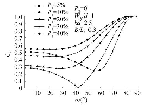
Fig. 16 shows the variations in Cr for different P1; here, P2 = 0, kd = 2.5, and all other conditions are identical to those in the previous case (WH/d = 1). For values of P1 ≤ 10%, Cr decreases and then increases. For values of P1 > 10%, all of the Cr coefficients behave similarly, remaining practically constant for α up to 40° and then increasing to reach 1 for α = 90°. The figure further demonstrates that the minimum values of Cr are achieved at P1 = 10%.
|
Figure 16 Variations in Cr versus incident wave angles for different values of P1 |
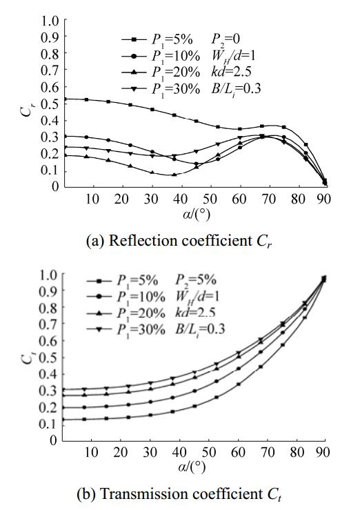
When the back wall of the previous example is given some permeability (P2=5%), the results are somehow altered to allow for the wave to transmit. Fig. 17 shows that Cr values are further decreased from their counterparts in Fig. 16, but the Ct values indicate some wave transmission. At the limit α = 90°, the values of Cr tend to approach zero and Ct = 1. The minimum values of Cr correspond to P1 = 20%. When the front wall porosity is above 10%, both reflection and transmission coefficients are below 0.3 for a wide range of incident wave angles.
|
Figure 17 Variations in Cr and Ct versus incident wave angles for different values of P1 |
Fig. 18 demonstrates the effects of varying B/Li on Cr for different α and kd = 1 in a breakwater system extending to the seabed (WH/d = 1) with P1 = 10% and an impermeable back wall (P2 = 0%). To take into account the obliquity of the waves, the x coordinate is taken as Bcos(α)/Li(Huang, 2011).

|
Figure 18 Variations in Cr versus the relative chamber width Bcos(α)/Li for different incident wave angles |
For any α, Cr clearly oscillates between the minima occurring at Bcos(α)/Li = 0.25 + 0.5n (n = 0, 1, 2, …) and the maxima (Cr = 1) at Bcos(α)/Li = 0.5 + 0.5n. This is true when inertial effects associated with the porous wall are ignored. For practical applications, only the first mode, that is, for n = 0, is of interest. For any particular value of Bcos(α)/Li, the reflection increases with increasing α. Similar conclusions were made by Huang (2011) for a similar type of breakwater.
5 ConclusionsIn the present work, an MDBEM approach was developed to analyze the reflection and transmission of waves from single-chamber (double-porous walls) breakwater systems. The method was first validated against previous analytical and experimental data available in the literature. The present computations showed that Cr and Ct depend on a large number of parameters, including α, kd, WH/d, P, and B/Li. To improve the performance of the breakwater, P1 ought to be 10% larger than P2. Increasing P1 increases wave dissipation and, hence, decreases reflection. Incident wave angles exert effects on transmission and reflection only at α larger than 40°. At α ≤ 40°, Cr and Ct do not vary significantly and can be treated with certainty as constant. To eliminate wave transmission altogether, using a breakwater with an impermeable back wall is recommended. P1 could be optimized to deliver a minimum reflection; specifically, a front porous wall with 10% porosity was shown to deliver optimum reflections for a wide range of α.
Behera H, Kaligatla RB, Sahoo T, 2015a. Wave trapping by porous barrier in the presence of step type bottom. Wave Motion, 57, 219-230. DOI: http://dx.doi.org/10.1016/j.wavemoti.2015.04.005
( 0) 0)
|
Behera H, Koley S, Sahoo T, 2015b. Wave transmission by partial porous structures in two-layer fluid. Engineering Analysis with Boundary Elements, 58, 58-78. DOI: http://dx.doi.org/10.1016/j.enganabound.2015.03.010
( 0) 0)
|
Bélorgey M, Rousset JM, Carpentier G, 2003. Perforated breakwaters, Dieppe harbour Jarlan caisson: general schedule and acquired experience. Proceedings of 13th International Offshore and Polar Engineering Conference: ISOPE, Honolulu, USA, 850-857. http://www.onepetro.org/conference-paper/ISOPE-I-03-324
( 0) 0)
|
Das P, Dolai D, Mandal B, 1997. Oblique wave diffraction by parallel thin vertical barriers with gaps. Journal of Waterway, Port, Coastal, and Ocean Engineering: ASCE, 123(4), 163–171. DOI: http://dx.doi.org/10.1061/(ASCE)0733-950X(1997)123:4(163)
( 0) 0)
|
Hagiwara K, 1984. Analysis of upright structure for wave dissipation using integral equation. Proceedings of 19th International Conference on Coastal Engineering: ASCE, Houston, USA, 1984, 2810-2826. http://ascelibrary.org/doi/10.1061/9780872624382.189
( 0) 0)
|
Huang Z, 2007. Wave interaction with one or two rows of closely spaced rectangular cylinders. Ocean Engineering, 34(11-12), 1584-1591. DOI: http://dx.doi.org/10.1016/j.oceaneng.2006.11.002
( 0) 0)
|
Huang Z, Li Y, Liu Y, 2011. Hydraulic performance and wave loadings of perforated/slotted coastal structures: A review. Ocean Engineering, 38(10), 1031-1053. DOI: http://dx.doi.org/10.1016/j.oceaneng.2011.03.002
( 0) 0)
|
Ijima T, Okuzono H, Ushifuza Y. The reflection coefficients of permeable quaywall with reservoir against obliquely incident waves[J]. Rep. Coll. Eng., Kyushu University, Japan, 1978, 51: 245-250. ( 0) 0)
|
Isaacson M, Baldwin J, Premasiri S, Yang G, 1999. Wave interactions with double slotted barriers. Applied Ocean Research, 21(2), 81-91. DOI: http://dx.doi.org/10.1016/S0141-1187(98)00039-X
( 0) 0)
|
Kaligatla RB, Koley S, Sahoo T. Trapping of surface gravity waves by a vertical flexible porous plate near a wall[J]. Zeitschrift für angewandte Mathematik und Physik, 2015, 66(5): 2677-2702. DOI:10.1007/s00033-015-0521-2 ( 0) 0)
|
Koley S, Behera H, Sahoo T. Oblique wave trapping by porous structures near a wall[J]. Journal of Engineering Mechanics, 2015, 141(3): 04014122. DOI:10.1061/(ASCE)EM.1943-7889.0000843 ( 0) 0)
|
Li Y, Liu Y, Teng B, Sun D. Reflection of oblique incident waves by breakwaters with partially-perforated wall[J]. China Ocean Engineering, 2002, 16(3): 329-342. DOI:10.3321/j.issn:0890-5487.2002.03.006 ( 0) 0)
|
Li Y, Liu Y, Teng B, 2006. Porous effect parameter of thin permeable plates. Coastal Engineering Journal, 48(4), 309-336. DOI: http://dx.doi.org/10.1142/S0578563406001441
( 0) 0)
|
Liu H, Liu Y, Li Y. The theoretical study on diagonal wave interaction with perforated-wall breakwater with rock fill[J]. Acta Oceanologica Sinica, 2009, 28(6): 103-110. DOI:10.3969/j.issn.0253-505X.2009.06.011 ( 0) 0)
|
Liu Y, Li Y, 2010. The interaction of oblique waves with a partially immersed wave absorbing breakwater. Proceedings of 32nd International Conference on Coastal Engineering: ASCE, Shanghai, China, 2010, 32(1). http://journals.tdl.org/icce/article/viewArticle/1273
( 0) 0)
|
Liu Y, Li Y, 2011. Wave interaction with a wave absorbing double curtain-wall breakwater. Ocean Engineering, 38(10), 1237-1245. DOI: http://dx.doi.org/10.1016/j.oceaneng.2011.05.009
( 0) 0)
|
Liu Y, Li Y, Teng B, 2007. The reflection of oblique waves by an infinite number of partially perforated caissons. Ocean Engineering, 34(14-15), 1965-1976. DOI: http://dx.doi.org/10.1016/j.oceaneng.2007.03.004
( 0) 0)
|
Liu Y, Li Y, Teng B. Interaction between obliquely incident waves and an infinite array of multi-chamber perforated caissons[J]. Journal of Engineering Mathematics, 2012, 74(1): 1-18. DOI:10.1007/s10665-011-9484-2 ( 0) 0)
|
Liu Y, Xie L, Zhang W. The wave motion over a submerged Jarlan-type perforated breakwater[J]. Acta Oceanologica Sinica, 2014, 33(5): 96-102. DOI:10.1007/s13131-014-0471-0 ( 0) 0)
|
Mandal S, Behera H, Sahoo T. Oblique wave interaction with porous, flexible barriers in a two-layer fluid[J]. Journal of Engineering Mathematics, 2016, 100(1): 1-31. DOI:10.1007/s10665-015-9830-x ( 0) 0)
|
Porter R, 1995. Complementary methods and bounds in linear water waves. PhD thesis, University of Bristol, UK.
( 0) 0)
|
Porter R, Evans D, 1995. Complementary approximations to wave scattering by vertical barriers. Fluid Mechanics, 294, 155-180. DOI: https://doi.org/10.1017/S0022112095002849
( 0) 0)
|
Suh K, Park W. Wave reflection from perforated-wall caisson breakwaters[J]. Coastal Engineering, 1995, 26(3-4): 177-193. DOI:10.1016/0378-3839(95)00027-5 ( 0) 0)
|
Teng B, Zhang X, Ning D, 2004. Interaction of oblique waves with infinite number of perforated caissons. Ocean Engineering, 31(5-6), 615-632. DOI: http://dx.doi.org/10.1016/j.oceaneng.2003.08.001
( 0) 0)
|
Yu X, 1995. Diffraction of water waves by porous breakwaters. Journal of Waterway, Port, Coastal, and Ocean Engineering: ASCE, 121(6), 275-282. DOI: http://dx.doi.org/10.1061/(ASCE)0733-950X(1995)121:6(275)
( 0) 0)
|
Yueh C-Y, Chuang S-H, 2012. A boundary element model for a partially piston-type porous wave energy converter in gravity waves. Engineering Analysis with Boundary Elements, 36(5), 658-664. DOI: http://dx.doi.org/10.1016/j.enganabound.2011.11.011
( 0) 0)
|
 2017, Vol. 16


