1 Introduction
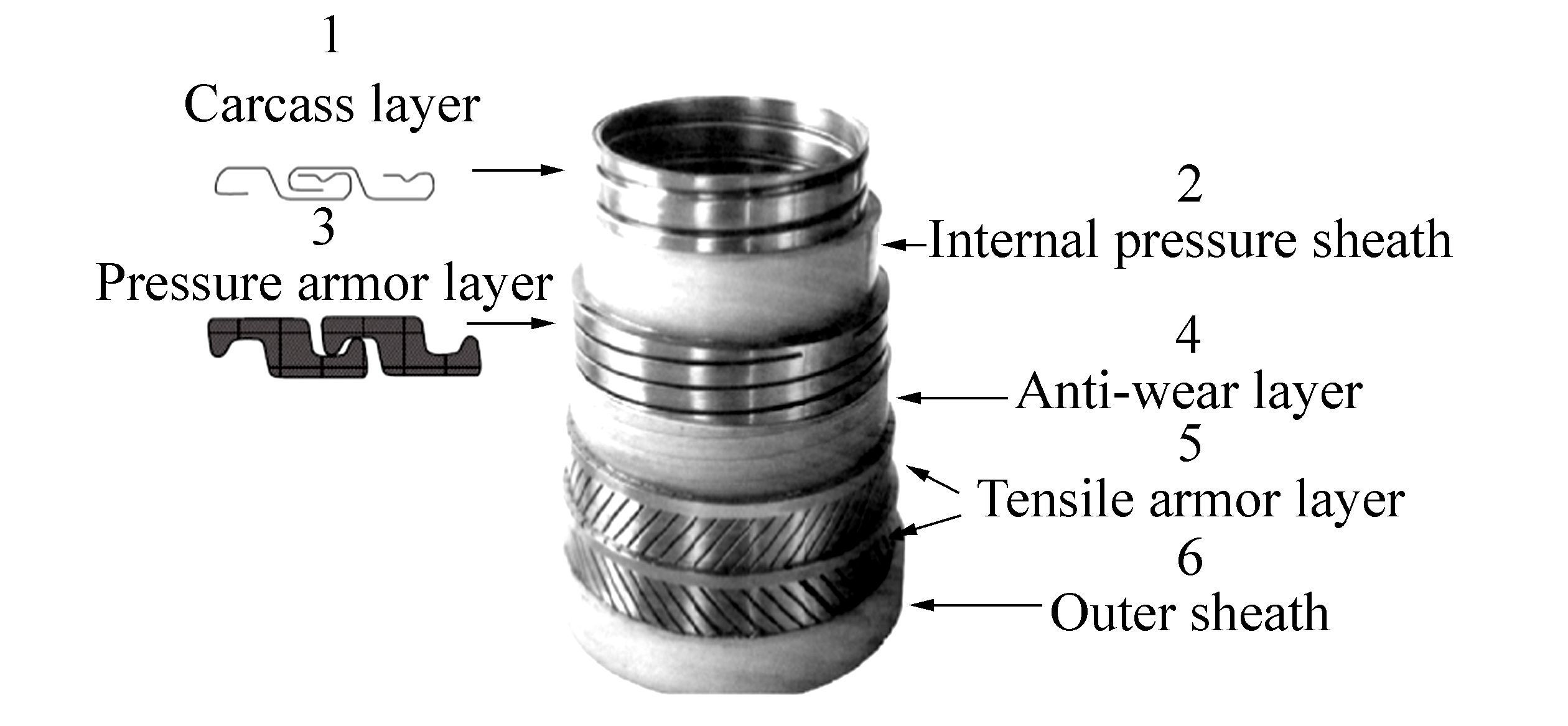
The flexible riser is a key component of an oil and gas production system comprising polymeric and metallic layers with different functions. Polymeric layers often provide sealing or insulation for internal and external fluids and reduce metallic friction. Metallic layers generally include the innermost carcass, profiled Z-shaped pressure armor layer, and tensile armor layer. The first two kinds of layers are interlocked and wound at a lay angle close to 90° and mainly resist the inward and outward pressures, respectively. The tensile armor layers with rectangular cross-section helical wires have two or four layers, and are cross-wound at lay angles between 20° and 55° (De Sousa et al., 2012). This kind of layer is designed to carry the tension, torque, and pressure end cap effect.
Compared with the conventional steel riser, the flexible riser can withstand large bending deformation without compromising the axial stiffness and the pressure integrity. It also has advantages in the aspects of storage in long lengths on the reel and in the installation cost (de Sousa et al., 2009). However, its complex construction significantly increases the difficulty of performance assessment, thereby attracting much research attention. A helical wire is one of the critical components prone to fatigue failure. An integrated model for the flexible riser should first be established to predict the fatigue damage of the helical wire. The commonly used method is analytical formulation, which can partly explain the nonlinear mechanism of flexible pipes and is time efficient (Wang and Chen, 2011). Witz and Tan (1992a; 1992b) proposed an analytical model to predict the axial–torsional and bending structural behaviors of a flexible pipe. Kraincanic and Kebadze (2001) investigated the slip initiation and progression in the helical wire of a flexible pipe and derived the bending moment–curvature relationship, which showed good agreement with the experimental data. Bahtui et al. (2009) proposed an approach to model the axisymmetric and bending response in a whole matrix and compared it with a detailed FE model.
The helical wire stress can be further investigated based on analytical formulations. Leroy and Estrier (2001) studied the dynamic stress in the helical wire based on its geometrical, friction, and equilibrium equations. They then validated the proposed method using the measured strain. Sævik (2011) applied two alternative approaches to predict the bending stress in the helical wire of a flexible pipe, in which the nonlinear bending moment–curvature relationship and the sandwich beam theory were used to describe the stick–slip behavior of the helical wire. The obtained stress is compared with the experimental data, and the results showed good agreement. Skeie et al. (2012) investigated the helical wire stress considering the local bending, and demonstrated the stress range at different circumferential positions. Tang et al. (2015) studied the validity and limitation of several analytical models for the bending stress calculation of the helical wire by using a detailed FE model.
The traditional method for fatigue damage assessment often first performs a global analysis of the flexible riser using constant bending stiffness and then transports the global response to the local model for the stress calculation of the helical wire (de Sousa et al., 2012). Tan et al. (2007) implemented the in-house hysteretic model of Wellstream as an external function of OrcaFlex to simulate the global response of the flexible riser. The results illustrated the necessity of considering the bending stiffness variation in the global analysis. Although researches on the flexible riser have been extensively conducted in the recent years, the stress characteristics of the helical wire under an irregular response, including the bending stiffness variation, is still not investigated and presented.
This study presents a feasible model of the flexible riser under an irregular response and investigates the stress of the helical wire considering local flexure. The interlayer interaction under axisymmetric loads in the model is simulated by setting up dummy springs. The interlayer pressures are then obtained for the bending analysis. The bending stiffness is updated at each time step during the response analysis by determining the slipping region of the helical wires. An eight-layer flexible pipe in Witz (1996) is employed to verify the model. The stress at the critical point of the helical wire considering local flexure is then investigated.
2 MethodologyThe flexible riser has several different kinds of layers (Fig. 1), which are often treated individually, but have the same axial displacement uz, axial rotation φz, rotation φx about x axis, and φy about y-axis (Fig. 2). The radial displacement ur of each layer is modeled individually because the separation of the adjacent layers is allowed.
|
| Figure 1 Typical flexible riser components (De Sousa et al., 2014) |

|
| Figure 2 Displacement symbols of a layer and the critical point of helical wire |
The following assumptions are applied in the present study to formulate the flexible riser:
1) The helical wire only slides along its axial direction (i.e., the loxodromic curve) (Sævik, 2011).
2) The curvature is constant along the flexible riser element.
3) The interlayer contact pressure results from an axisymmetric response and remains constant during the bending behavior.
4) The sliding friction of the helical wire is equal to the maximum static friction.
5) The initial state of the helical wire is approximately a stress-free state (Skeie et al., 2012).
2.1 Axisymmetric formulationThe axisymmetric loads include the axial tension, torque, and internal and external pressures. The related tangent stiffness should be obtained to solve the displacements under these loads. The carcass armor and the pressure armor layer are often equivalent to the orthotropic cylinder. de Sousaet al. (2009, 2014) proposed an effective equivalent method based on the analogy between the helical tendon and the orthotropic shell. The method would not be detailed in the present study for brevity. After equivalence, the flexible riser layers can be divided into the cylindrical and helical layer categories. The helical layer mainly includes the tensile armor layer and the anti-wear layer.
The stress–strain relationship of a cylinder can be expressed as follows based on the Hooke's law:
| $\left\{ \begin{array}{l} {\sigma _1}\\ {\sigma _2}\\ {\sigma _{12}} \end{array} \right\} = \left[ {\begin{array}{*{20}{c}} {\frac{{{E_1}}}{{1 - {\nu _{12}}{\nu _{21}}}}}&{\frac{{{\nu _{12}}{E_1}}}{{1 - {\nu _{12}}{\nu _{21}}}}}&0\\ {\frac{{{\nu _{21}}{E_2}}}{{1 - {\nu _{12}}{\nu _{21}}}}}&{\frac{{{E_2}}}{{1 - {\nu _{12}}{\nu _{21}}}}}&0\\ 0&0&{{G_{12}}} \end{array}} \right]\left\{ {\begin{array}{*{20}{c}} {{\varepsilon _1}}\\ {{\varepsilon _2}}\\ {{\gamma _{12}}} \end{array}} \right\}$ | (1) |
where E, v, and G are the Young's modulus, Poisson ratio, and shear modulus, respectively. Subscripts 1 and 2 represent the axial and circumferential directions, respectively. For the isotropic polymeric layer, E1 is equal to E2 and v12 is equal to v21. The strains, as a function of the axisymmetric displacements, are described by the following equations (McNamara and Harte, 1989):
| ${\varepsilon _1} = \frac{{{u_z}}}{L},{\rm{ }}{\varepsilon _2} = \frac{{{u_r}}}{R},{\rm{ }}{\gamma _{12}} = R\frac{{{\phi _z}}}{L}$ | (2) |
where L and R represent the length and the radius of the cylinder, respectively.
The linearized axial strain for the helical layer is expressed as follows (Sævik, 2011):
| ${\varepsilon _{0X}} = \frac{{{u_z}}}{L}{\cos ^2}\left( \alpha \right) + \frac{{{u_r}}}{R}{\sin ^2}\left( \alpha \right) + R\frac{{{\phi _z}}}{L}\sin \left( \alpha \right)\cos \left( \alpha \right)$ | (3) |
where α is the lay angle of the helical wire.
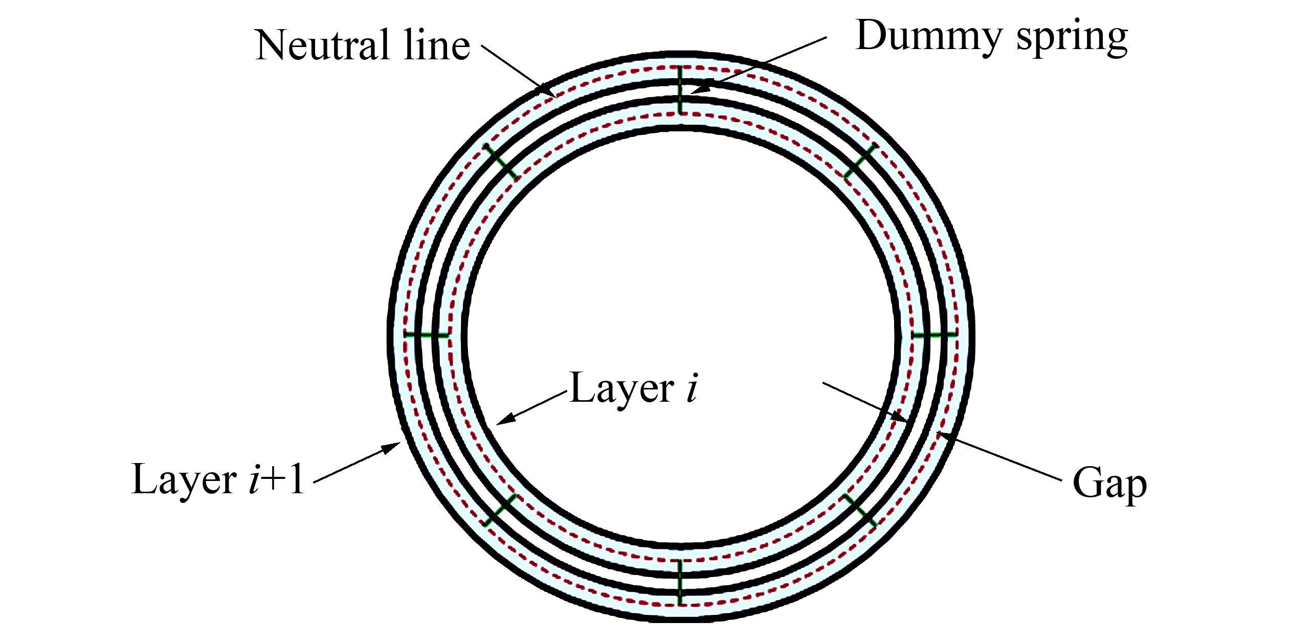
The treatment of the interlayer interaction should be elaborated under the axisymmetric loads. Witz and Tan (1992a) and Bahtuiet al. (2009) investigated the modeling of the interlayer interaction based on the structural continuity and equilibrium along the radial direction. The former described the pressure difference of the helical wire as a function of the local curvature, bending moment, and torque, whereas the latter referred to the research work of Lanteigne (1985), where the pressure difference of the helical wire was related with the axial strain. The interlayer interaction in the present study is simulated by setting dummy springs between the medium lines of the adjacent layers (Fig. 3).
|
| Figure 3 Sketch of the interlayer interaction model |
The strain energy U and the work W related with the external force are obtained as follows based on the principle of virtual work:
| $U = \sum\limits_{i = 1}^N {\int {\int {\int {\left( {\frac{1}{2}\mathit{\boldsymbol{\sigma }}_i^{\rm{T}}{\mathit{\boldsymbol{\varepsilon }}_i}} \right)} } } } {\rm{d}}V + \sum\limits_{i = 1}^{N - 1} {L{k_i}} {\left( {{u_{r,i}} - {u_{r,i + 1}}} \right)^2}$ | (4) |
| $\begin{array}{l} W = F{u_z} + T{\phi _z} + \\ \left[ {{P_{{\rm{in}}}}R_2^2\left( {\frac{{{u_z}}}{L} + \frac{{2{u_{r,2}}}}{R}} \right) - {P_{{\rm{out}}}}R_N^2\left( {\frac{{{u_z}}}{L} + \frac{{2{u_{r,N}}}}{R}} \right)} \right]{\rm{\pi }}L \end{array}$ | (5) |
where N is the number of layers; subscript i is the ith layer; F and T are the axial force and torque, respectively; and Pin and Pout are the internal and external pressures, respectively. The internal pressure is directly exerted on the internal pressure sheath, considering that the innermost carcass armor is not waterproof. k is the stiffness of the dummy springs, which would be iteratively adjusted based on the interlayer penetration and the separation condition. The interlayer penetration corresponds to an increasing ki, whereas the interlayer separation corresponds to a decreasing ki. The interlayer contact pressure can be calculated based on the convergent ki and the interlayer radial displacement.
The equilibrium equation of the flexible riser in the form of a matrix can be given as follows by letting U= W:
| $\left[ {\begin{array}{*{20}{c}} {{K_{11}}}&{{K_{12}}}& \cdots &{{K_{1j}}}& \cdots \\ {{K_{21}}}&{{K_{22}}}& \cdots &{{K_{2j}}}& \cdots \\ \vdots & \vdots & \ddots &0&0\\ {{K_{j1}}}&{{K_{j2}}}&0&{{K_{jj}}}&{{K_{j\left( {j + 1} \right)}}}\\ \vdots & \vdots &0&{{K_{\left( {j + 1} \right)j}}}& \ddots \end{array}} \right]\left\{ {\begin{array}{*{20}{c}} {\frac{{{u_z}}}{L}}\\ {\frac{{{\phi _z}}}{L}}\\ \vdots \\ {\frac{{{u_{r,j - 2}}}}{{{R_{j - 2}}}}}\\ \vdots \end{array}} \right\} = \left\{ {\begin{array}{*{20}{c}} {\bar F}\\ T\\ \vdots \\ {{{\bar P}_{j - 2}}}\\ \vdots \end{array}} \right\}$ | (6) |
where the matrix dimension is (N+2)×(N+2) and the elements are given in the Appendix.
2.2 Axisymmetric formulationThe bending nonlinearity of the flexible riser is mainly related with the stick–slip behavior of the helical wire. The helical wire starts to slip at the position near the neutral surface when the bending curvature reaches the minimum critical value, and then propagates with the increasing curvature until full slippage happens. The non-slipping and slipping axial strains induced by the bending response are presented as follows (Dong et al., 2013):
| ${\varepsilon _{0X}} = \left\{ \begin{array}{l} R{\cos ^2}\left( \alpha \right)\sin \left( \theta \right)\kappa {\rm{ Sticking}}\\ \left( {{P_1}{f_1} + {P_2}{f_2}} \right)\frac{{R\theta }}{{E\sin \left( \alpha \right)t}}{\rm{ Slipping}} \end{array} \right.$ | (7) |
where κ is the curvature; θ is the angular position in the range of [0, π/2] (Fig. 2); P1 and P2 are the internal and external pressures of the helical armor obtained based on the above axisymmetric model; f1 and f2 are the corresponding friction coefficients; and t is the layer thickness. This study takes the bending around the x axis as an example. Thus, κ is equal to φx/L.
The equilibrium between the strain energy and the work done by the bending moment under the virtual curvature increment can be expressed as follows because the slipping part of the helical wire keeps stress constant and would not contribute to the strain energy associated with the curvature variation:
| $\begin{array}{l} \Delta {M_x}\partial {\phi _x} = \int {\int\limits_V {\int {E{{\left( {\delta {\varepsilon _{0X}}} \right)}^2}{\rm{d}}V = } } } \\ \int\limits_0^L {\int\limits_{R - t/2}^{R + t/2} {\left[ {4\int\limits_{{\theta _{cr}}}^{{\rm{\pi }}/2} {E{R^2}{{\cos }^4}\left( \alpha \right){{\sin }^2}\left( \theta \right)} \left( {\frac{{nb}}{{2{\rm{\pi }}}}{\rm{d}}\theta } \right)} \right]{\rm{d}}r} } \\ \frac{{{\rm{d}}l}}{{\cos \alpha }}{\left( {\frac{{\delta {\phi _x}}}{L}} \right)^2} = E{I_0}\left( {1 - \frac{2}{{\rm{\pi }}}{\theta _{cr}} + \frac{1}{{\rm{\pi }}}\sin \left( {2{\theta _{cr}}} \right)} \right)\frac{{\delta {\phi _x}}}{L}\delta {\phi _x} \end{array}$ | (8) |
Thus, the tangent bending stiffness of the helical armor is given as:
| $EI = E{I_0}\left( {1 - \frac{2}{{\rm{\pi }}}{\theta _{cr}} + \frac{1}{{\rm{\pi }}}\sin \left( {2{\theta _{cr}}} \right)} \right)$ | (9) |
where ΔMx is the bending moment around the x axis associated with the virtual curvature increment of δκ = δφx/L; θcr is the boundary of the sticking and slipping parts in the range of [0, π/2]; and
Conventional studies often investigate the full loop of the hysteretic bending moment–curvature relationship, which only provides the bending stiffness under a regular response. The present study tracks the axial stresses along angular positions at each time step to determine the slipping region (i.e., θcr). The bending stiffness is then calculated for the next time step. The slipping region can be determined as follows based on the axial stress gradient (Tan et al., 2007, Dong et al., 2015):
| $\begin{array}{l} {\rm{Slipping}}:{\rm{ }}\left| {E\frac{{{\rm{d}}{\varepsilon _{0X}}}}{{{\rm{d}}X}}A} \right| \ge {F_f}\\ {\rm{Sticking}}:{\rm{ }}\left| {E\frac{{{\rm{d}}{\varepsilon _{0X}}}}{{{\rm{d}}X}}A} \right| < {F_f} \end{array}$ | (10) |
where
The above mentioned bending stiffness of the helical wire only considers the effect of the axial stress of the helical wires. Donget al. (2013) investigated the effect of the local flexure of the helical wires on the bending stiffness. They found that the effect was negligible for the non-slipping state, but obvious for the full-slipping state. The contribution of the helical wire's local flexure to the bending stiffness can be described as follows:
| $\begin{array}{l} E{I_{bt}} = \frac{1}{2}n\left( {E{I_Z}\left( {1 + {{\sin }^2}\alpha } \right)\cos \alpha + } \right.\\ \left. {E{I_Y}{{\cos }^7}\alpha + GJ{{\sin }^2}\alpha \cos {\alpha ^5}} \right) \end{array}$ | (11) |
where n is the number of the helical wires on the tensile armor layer; and IY, IZ, and J are the normal, transverse, and torsional moments of inertia, respectively.
The bending formulation of the cylindrical layer can be easily obtained. The related bending stiffness for the anti-wear layer can be calculated based on Eqs. (9) and (11). However, it may play a negligible role because of the small Young's modulus.
2.3 Stress at the critical pointThe linearized Green–Lagrange strain at the critical point of the helical wire considering the local flexure can be expressed as follows (Skeie et al., 2012):
| $\begin{array}{l} {\varepsilon _X} = {\varepsilon _{0X}} - Y\Delta {\kappa _Z} + Z\Delta {\kappa _Y}\\ 2{\varepsilon _{XY}} = Z\Delta {\kappa _X}\\ 2{\varepsilon _{XZ}} = - Y\Delta {\kappa _X} \end{array}$ | (12) |
where
The local flexure increments induced by axisymmetric response are given as follows (Sævik, 2011):
| $\begin{array}{l} \Delta {\kappa _X} = \frac{{{u_z}}}{L}\frac{{{{\sin }^3}\left( \alpha \right)\cos \left( \alpha \right)}}{R} - \\ \frac{{{u_r}}}{R}\frac{{{{\sin }^3}\left( \alpha \right)\cos \left( \alpha \right)}}{R} + \frac{{{\phi _z}}}{L}{\cos ^4}(\alpha )\\ \Delta {\kappa _Y} = - \frac{{{u_z}}}{L}\frac{{{{\sin }^2}\left( \alpha \right){{\cos }^2}\left( \alpha \right)}}{R} + \frac{{{u_r}}}{R}\frac{{{{\sin }^2}\left( \alpha \right){{\cos }^2}\left( \alpha \right)}}{R} + \\ \frac{{{\phi _z}}}{L}\left( {2\sin (\alpha ){{\cos }^3}\left( \alpha \right) + {{\sin }^3}(\alpha )\cos \left( \alpha \right)} \right)\\ \Delta {\kappa _Z} = 0 \end{array}$ | (13) |
This study presumes that the helical wire slips only along the axial direction (i.e., the loxodromic curve (Sævik, 2011)) and neglects the transverse slipping. Therefore, the increments of the local twist, normal, and transverse curvatures induced by the bending response are given as follows (Sævik, 2011; Skeie et al., 2012):
| $\begin{array}{l} \Delta {\kappa _X} = - \sin \left( \alpha \right){\cos ^3}\left( \alpha \right)\sin \left( \theta \right)\kappa \\ \Delta {\kappa _Y} = {\cos ^4}\left( \alpha \right)\sin \left( \theta \right)\kappa \\ \Delta {\kappa _Z} = \cos \left( \alpha \right)\left( {1 + {{\sin }^2}\left( \alpha \right)} \right)\cos \left( \theta \right)\kappa \end{array}$ | (14) |
The von Mises equivalent stress is not only used in the ultimate strength analysis, but also often used in the multiaxial fatigue assessment (Benasciutti, 2014). Hence, it would also be analyzed in this study. The expression is written as follows:
| ${\sigma _s} = \sqrt {{{\left( {E{\varepsilon _x}} \right)}^2} + 3\left( {{{\left( {G{\varepsilon _{XY}}} \right)}^2} + {{\left( {G{\varepsilon _{XZ}}} \right)}^2}} \right)} $ | (15) |
Witz (1996) reported an experimental study, where the tension–elongation and bending moment–curvature relationships were investigated in detail using a 2.5-inch unbonded flexible pipe. Table 1 shows the main parameters of this flexible pipe. Note that the experimental model did not include the outer sheath, instead of a fabric tape. This study employs this case to verify the above mentioned proposed axisymmetric and bending models. The friction coefficient between the metallic and anti-wear layers is 0.1 (Kraincanic and Kebadze, 2001).
| Layer No. | Inner diameter/mm | t/mm | α/(º) | E/MPa | v |
| 1 | 63.2 | 3.5 | -87.5 | 2.05×10⁵ | 0.29 |
| 2 | 70.3 | 4.9 | / | 284 | 0.30 |
| 3 | 80.1 | 6.2 | -85.5 | 2.05×10⁵ | 0.29 |
| 4 | 92.5 | 1.5 | -84.2 | 301 | 0.30 |
| 5 | 95.5 | 3.0 | -35.0 | 2.05×10⁵ | 0.29 |
| 4 | 101.5 | 1.5 | -84.7 | 301 | 0.3 |
| 5 | 104.5 | 3.0 | 35 | 2.05×10⁵ | 0.29 |
| Fabric tape | 110.3 | 0.5 | -84 | 600 | 0.3 |
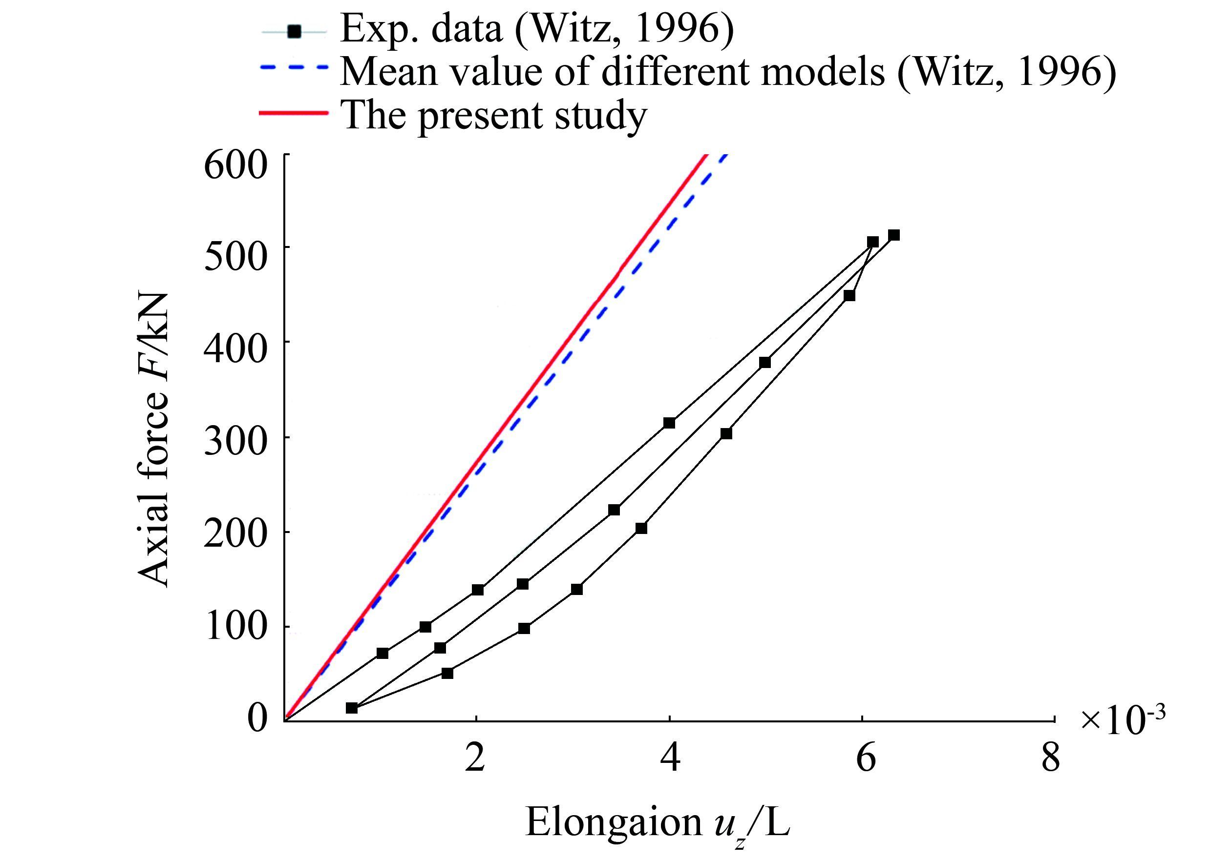
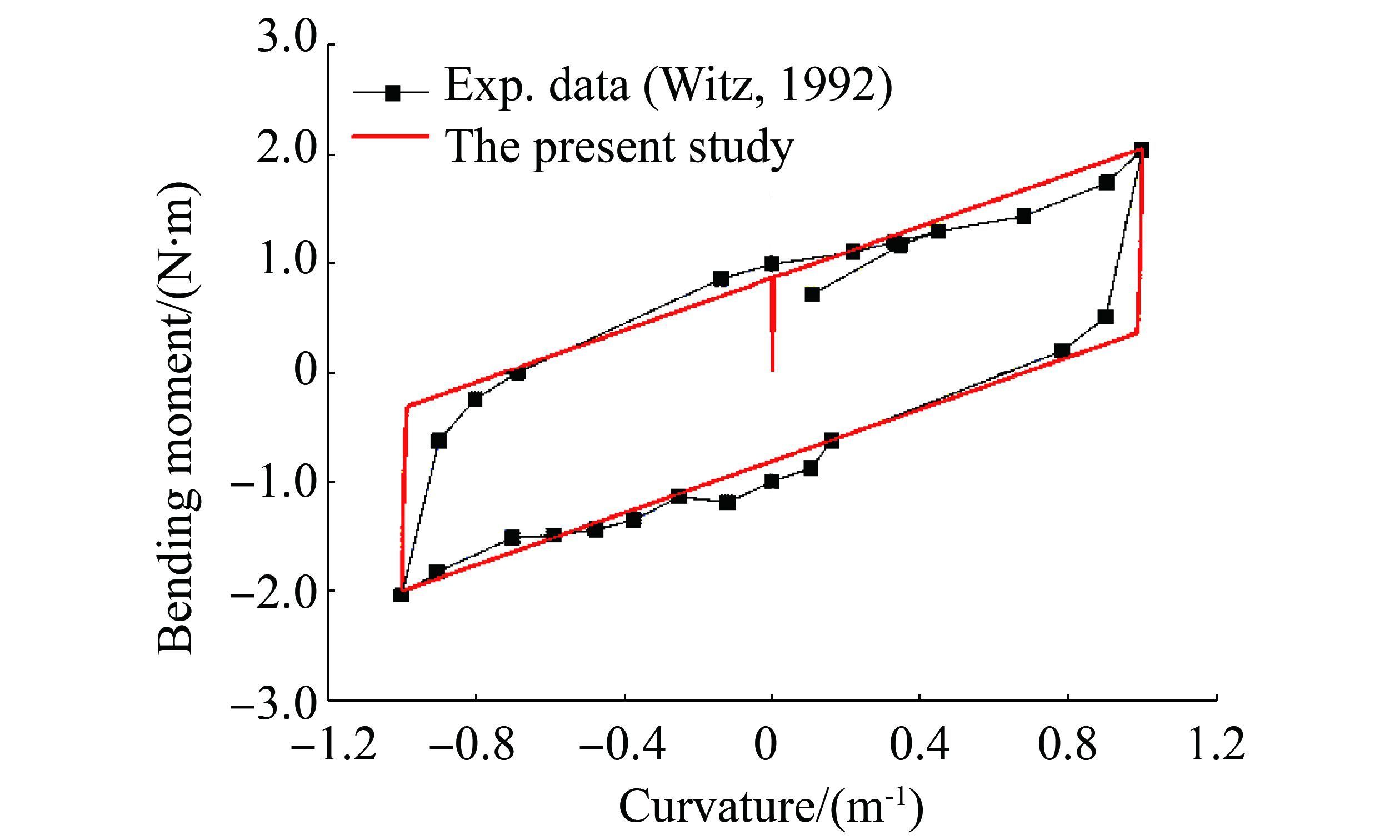
Fig. 4illustrates the axial force as a function of the elongation with the flexible pipe ends free to rotate. The present results are very similar with the mean value obtained using the models of different institutes (Witz, 1996). Compared with the experimental data, the present model overestimates the axial stiffness at a small elongation and fails to capture the unobvious hysteretic phenomenon, but predicts a relatively accurate axial stiffness with the increasing elongation. Fig. 5 shows the bending moment–curvature relationship under an internal pressure of 30 MPa. Before the bending analysis, the axisymmetric model is first applied to calculate the interlayer pressure. The numerically predicted hysteretic loop shows a good agreement with the experimental data. Overall, the proposed model can reasonably model the axial and bending stiffness of the unbonded flexible riser.
|
| Figure 4 Relationship between axial force and elongation |
|
| Figure 5 Relationship between bending moment and curvature |
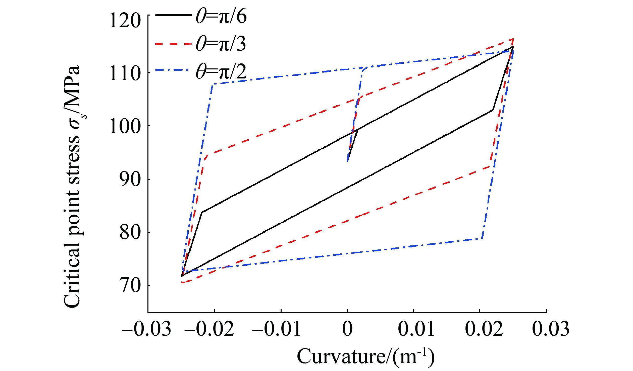
As regards the helical wire stress analysis, the predicted stress would remain constant when the slippage starts if only the axial stress is to be considered, and the stress induced by the local flexure is neglected. Moreover, a larger θ corresponds to a larger stress range according to Eq. (7). This condition may underestimate the stress range at critical positions and lead to a wrong selection of the fatigue failure position around the circumferential position. The present study takes the outer helical armor as an example and calculates the critical point stress at different angular positions by exerting a constant axial force and a regular curvature response on the above mentioned flexible pipe model: F=1.2×10⁵ N, κ∈[-0.025 m-1, 0.025 m-1]. Fig. 6 demonstrates the stress variation with curvature. Considering the effect of the local flexure at a critical point, the stress still linearly increases with a low slope when the slippage starts, and the slope decreases with the increasing θ. Therefore, the fatigue failure position of the helical wire may be near a neutral surface when subjected to a large curvature variation (Hobbs and Ghavami, 1982; Sævik and Berge, 1995).
|
| Figure 6 Relationship between bending moment and curvature |
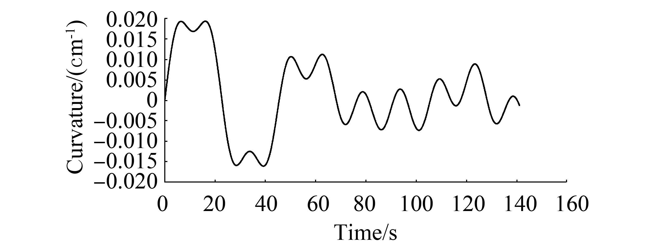
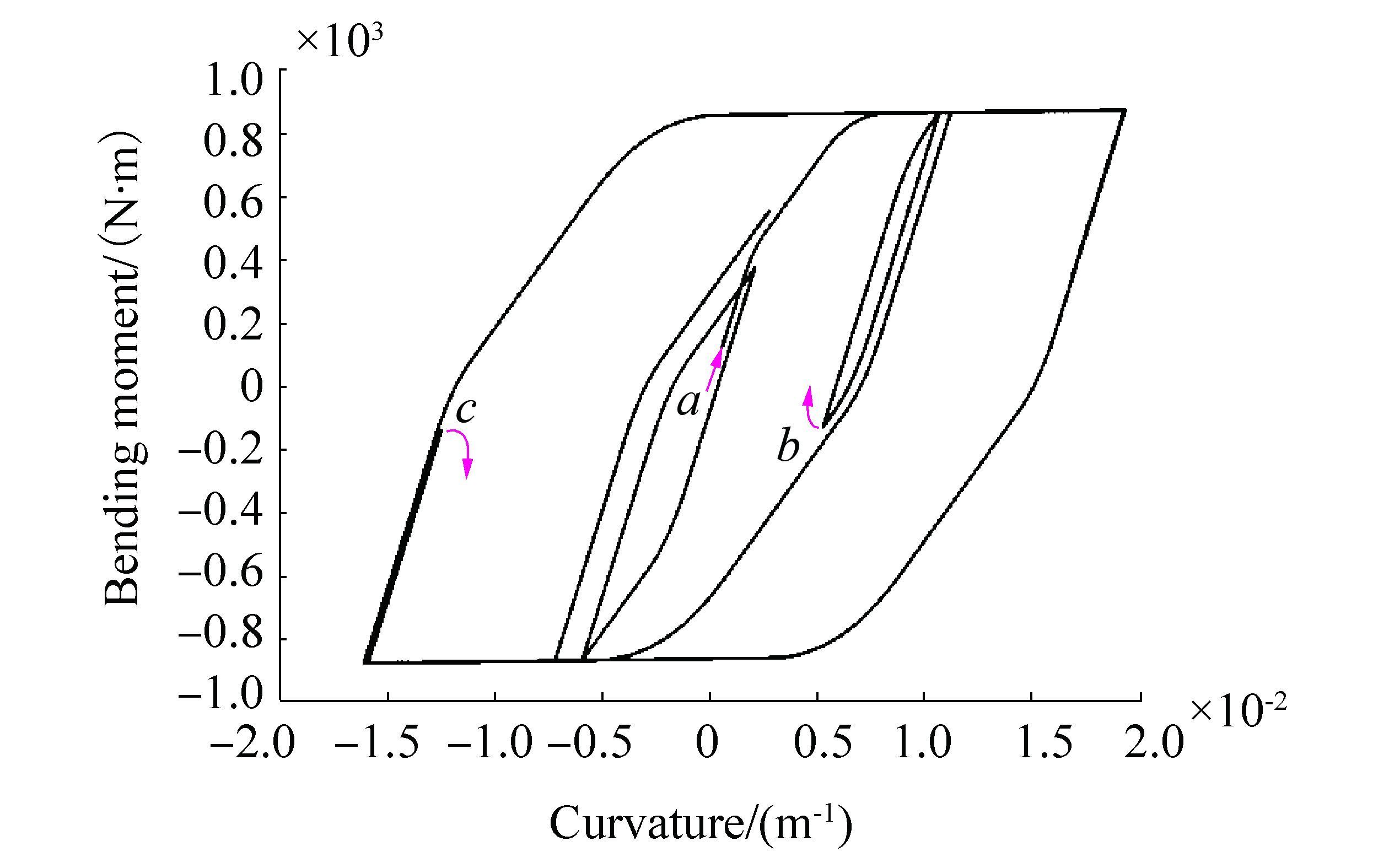
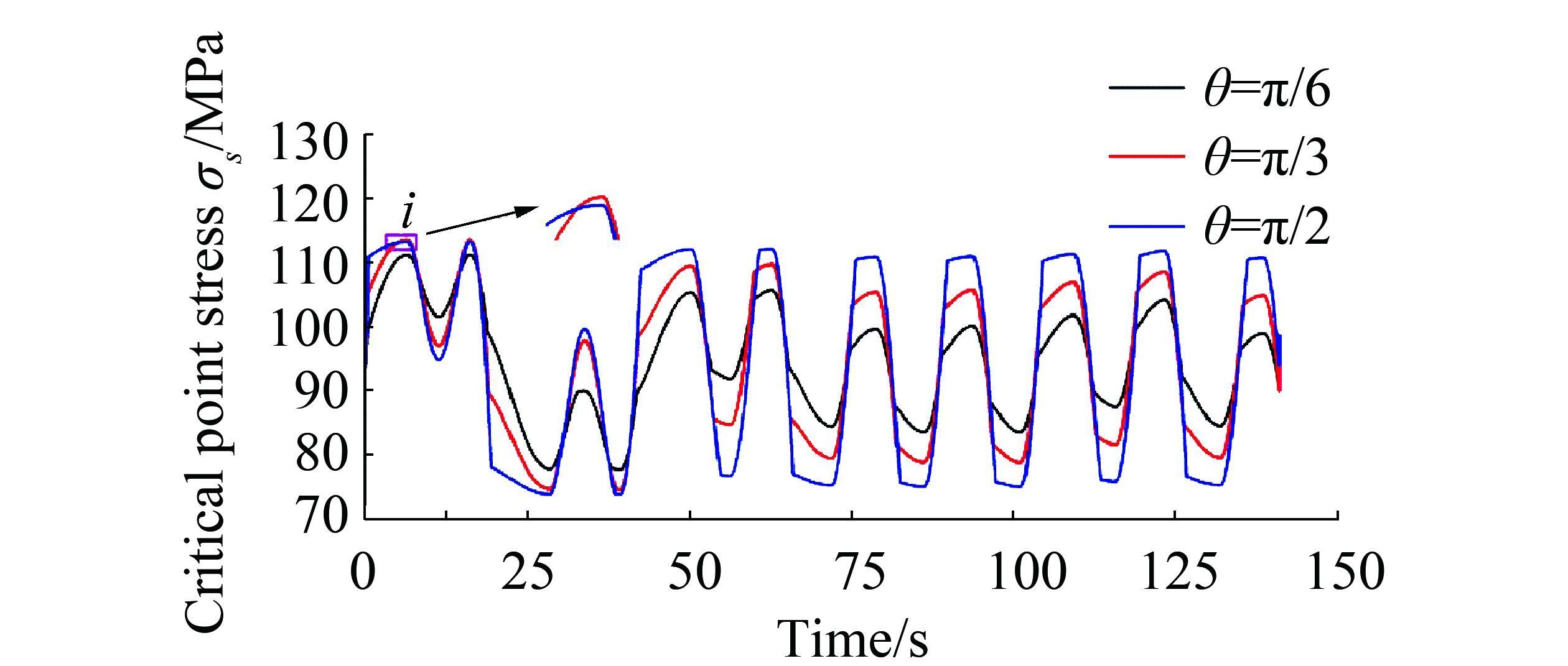
Published literatures mainly focused on the regular response analysis of flexible pipes and studied the full loop of the bending moment–curvature relationship based on the derived formula. The bending moment model in the present study calculates the axial stress of the helical wire around the circumferential position at each time step to judge whether slippage occurs, then obtains the bending stiffness for the next time step. Therefore, this model can be used in the irregular response analysis. An irregular curvature time history is exerted on the flexible pipe to demonstrate this feature (Fig. 7). For simplification, the irregular curvature response is directly obtained through the superposition of several sinusoidal responses, which ensures the slippage of the helical wire based on the critical curvature (Kraincanic and Kebadze, 2001). The axial force is F=1.2×10⁵ N. The time increment of the calculation is set to 0.02 s. Fig. 8 illustrates the bending moment–curvature relationship, where point a is the bending initiation position. Regardless of the slippage occurrence or absence, the inverse route would follows the curve with a non-slipping bending stiffness until slippage occurs again, such as the inverse at points b and c. Fig. 9 shows the time history of the critical point stress. At the initial response marked by circle i, the stress θ = π/3 exceeds that at θ = π/2 because of the relative large stress increment with an increasing curvature when the helical wire slips. However, for the subsequent response, the larger θ corresponds to a larger stress because of the small curvature.
|
| Figure 7 Curvature time history |
|
| Figure 8 Bending moment–curvature relationship under an irregular curvature load |
|
| Figure 9 Time histories of the critical point stresses at different angular points |
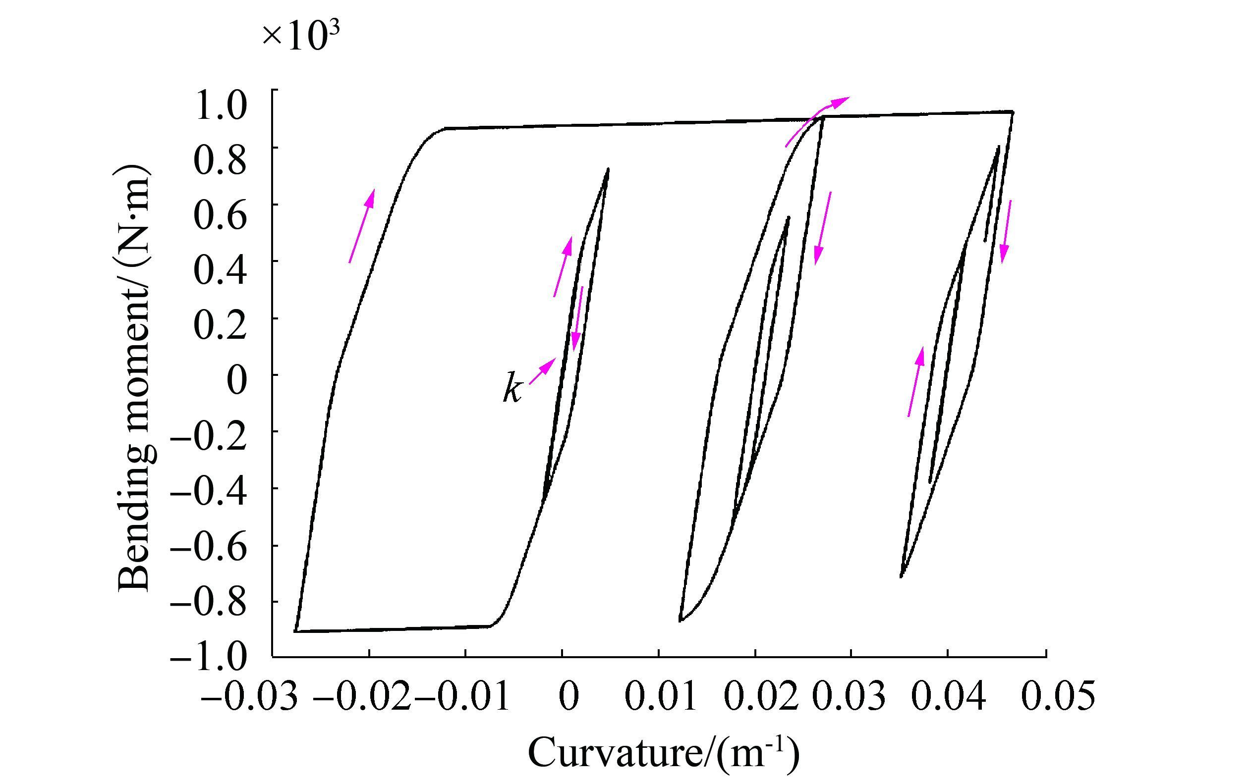
This section presents the response analysis of the flexible riser done by applying an irregular bending moment load and a constant axial force F=1.2×10⁵ N. Fig. 10 shows the bending moment history. The bending moment during the initial time is not large enough to make the helical wire slip, thus the bending moment–curvature relationship follows the curve in region k (Fig. 11). Note that the quasi-static method is applied in this analysis.

|
| Figure 10 Bending moment time history |
|
| Figure 11 Bending moment–curvature relationship under an irregular bending moment load |
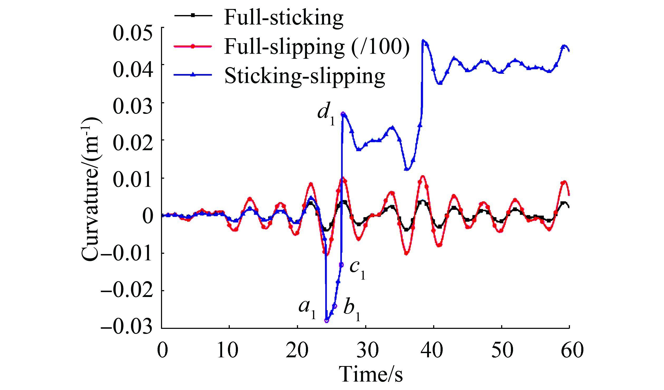
The conventional approach often assumes that the flexible riser is full-sticking or full-slipping in the global analysis. This study qualitatively discusses the effect of this approach on the predicted results. Fig. 12 shows a comparison of the curvatures predicted by three different models: 1) full-sticking, 2) full-slipping, and 3) present models. The curvature of the full-slipping model is very large because of the very small bending stiffness, and is divided by 100 in the plot. The full-sticking model has the same curvature with the present model during the initial time because the helical wire does not slip. However, the curvature of the present model significantly changes when the full-slipping occurs. The flexible riser maintains full-sticking from points a1 to b1, then partial-slipping from points b1 to c1 and full-slipping from points c1 to d1. Correspondingly, the critical point stress at θ = π/3 varies along a2→b2→c2→d2 in Fig. 13. Note that although the curvature changes relatively little from points a1 to b1, the corresponding critical point stress variation from points a2 to b2 is obvious because of the full-sticking. However, the large curvature variation from c1 to d1 results in a relatively small critical point stress variation from c2 to d2 because of the full-slipping. The increasing rate of the stress is small when slippage occurs, as discussed in Section 4.1.
|
| Figure 12 Comparison of the curvature obtained from three different models |

|
| Figure 13 Critical point stress at θ= π/3 under an irregular bending moment load |
The present study proposed an analytical model for the flexible riser. The axisymmetric and bending analyzes for this model were performed separately by assuming that the interlayer contact pressure remained constant during the bending response. Dummy springs, whose stiffness changed with the interlayer gap amplitude during the iterative calculation, were set between the layers to calculate the interlayer pressure under axisymmetric loads. The tangent stiffness matrix associated with the axisymmetric and the tangent bending stiffness were derived based on the virtual energy theory. The axial stress gradients of the helical wire around the circumferential direction were calculated at each time step in the bending analysis to judge whether slippage occurs. The slipping region was then obtained to determine the bending stiffness for the next time step.
This model was feasible for an irregular bending response. The proposed model was verified against an experimental model in the literature. The predicted axial force–elongation and bending moment–curvature relationships showed good agreement with the experimental data.
The bending moment–curvature relationship under an irregular response was demonstrated based on the proposed model. The critical point stress of the helical wire was also investigated by considering the local flexure. The results indicated that the critical point stress still linearly increased with the increasing curvature after slipping, but the slope was smaller than that before slipping. This result was different from that of the traditional approach, which only considered the axial stress that would remain constant after slipping. In addition, the larger angular position θ corresponded to a larger slope after slipping, which was in contrast with the law before slipping. Therefore, a small angular position θ may have a relatively large critical point stress under a large curvature. The flexible riser responses obtained from the conventional models with a constant bending stiffness and those from the present model were also compared. The curvature predicted by the present model sharply increased when slippage occurred and was obviously larger than that predicted by the full-sticking model.
In conclusion, the proposed model can well capture the hysteretic relationship between the bending moment and the curvature. It can also predict the helical wire stress at a critical point under an irregular response. Therefore, this model can be implemented in an unbonded flexible riser global analysis for a more accurate fatigue damage prediction.
Appendix
| $\begin{array}{*{20}{l}} {{K_{11}} = \sum\limits_{i = 1}^N {{g_{11,i}}} }\\ {{g_{11,i}} = \left\{ {\begin{array}{*{20}{c}} {\frac{{{{\left( {{E_1}A} \right)}_i}}}{{1 - {{\left( {{v_{12}}{v_{21}}} \right)}_i}}}\quad \;\quad {\rm{Cylindericallayer}}}\\ {{n_i}{E_i}{A_i}{{\cos }^3}\left( {{\alpha _i}} \right)\quad {\rm{Helicalarmor}}} \end{array}} \right.} \end{array}$ | (A1) |
| $\begin{array}{*{20}{l}} {{K_{12}} = \sum\limits_{i = 1}^N {{g_{12,i}}} }\\ {{g_{12,i}} = \left\{ {\begin{array}{*{20}{c}} {0\quad \quad \quad \quad \quad \quad \quad \quad \quad {\rm{Cylindericallayer}}}\\ {{n_i}{E_i}{A_i}{R_i}\sin \left( {{\alpha _i}} \right){{\cos }^2}\left( {{\alpha _i}} \right)\quad {\rm{Helicalarmor}}} \end{array}} \right.} \end{array}$ | (A2) |
| $\begin{array}{*{20}{l}} {{K_{1j}} = \left\{ {\begin{array}{*{20}{c}} {\frac{{{{\left( {{v_{12}}{E_1}A} \right)}_i}}}{{1 - {{\left( {{v_{12}}{v_{21}}} \right)}_i}}}\quad \quad \quad {\rm{Cylindericallayer}}}\\ {{n_i}{E_i}{A_i}\cos \left( {{\alpha _i}} \right){{\sin }^2}\left( {{\alpha _i}} \right)\quad {\rm{Helicalarmor}}} \end{array}} \right.}\\ {\left( {j > {\rm{2}};i = j - 2} \right)} \end{array}$ | (A3) |
| $\begin{array}{*{20}{l}} {{K_{22}} = \sum\limits_{i = 1}^N {{g_{22,i}}} }\\ {{g_{22,i}} = \left\{ {\begin{array}{*{20}{c}} {{{\left( {{G_{12}}{I_z}} \right)}_i}\quad \quad \quad \quad \quad \quad \;{\rm{Cylindericallayer}}}\\ {{n_i}{E_i}{A_i}R_i^2{{\sin }^2}\left( \alpha \right)\cos \left( {{\alpha _i}} \right)\;\;{\rm{Helicalarmor}}} \end{array}} \right.} \end{array}$ | (A4) |
| $\begin{array}{*{20}{l}} {{K_{2j}} = \left\{ {\begin{array}{*{20}{c}} {0\quad \quad \quad \quad \quad \quad \;{\rm{Cylindericallayer}}}\\ {{n_i}{E_i}{A_i}{R_i}{{\sin }^3}\left( {{\alpha _i}} \right)\;\;\;{\rm{Helicalarmor}}} \end{array}} \right.}\\ {\left( {j > {\rm{2and}}i = j - 2} \right)} \end{array}$ | (A5) |
| $\begin{array}{*{20}{l}} {{K_{jj}} = {g_{jj}} + {h_{jj}}}\\ {{g_{jj}} = \left\{ {\begin{array}{*{20}{c}} {\frac{{{{\left( {EA} \right)}_i}}}{{1 - {{\left( {{v_{12}}{v_{21}}} \right)}_i}}}\quad {\rm{Cylindericallayer}}}\\ {{n_i}{E_i}{A_i}\frac{{{{\sin }^4}\left( {{\alpha _i}} \right)}}{{\cos \left( {{\alpha _i}} \right)}}\;\;{\rm{Helicalarmor}}} \end{array}} \right.}\\ {{h_{jj}} = \left\{ {\begin{array}{*{20}{c}} {\begin{array}{*{20}{l}} {\frac{1}{2}{k_i}R_i^2i{\rm{ = 1}}}\\ {\frac{1}{2}{k_{i - 1}}R_{i - 1}^2i{\rm{ = }}N} \end{array}}\\ {\frac{1}{2}\left( {{k_{i - 1}}R_{i - 1}^2 + {k_i}R_i^2} \right){\rm{1}} < i < N} \end{array}} \right.}\\ {\left( {j > {\rm{2and}}i = j - 2} \right)} \end{array}$ | (A6) |
| ${K_{j\left( {j + 1} \right)}} = - \frac{1}{2}{k_i}{R_i}{R_{i + 1}}{\rm{ 2}} < {\rm{ }}j < 2 + N{\rm{ and }}i = j - 2$ | (A7) |
| $\bar F = F + {\rm{\pi }}\left( {{P_{{\rm{in}}}}R_2^2 - {P_{{\rm{out}}}}R_N^2} \right)$ | (A8) |
| ${\bar P_{j - 2}} = \left\{ {\begin{array}{*{20}{c}} {2{\rm{\pi }}{P_{{\rm{in}}}}R_2^2{\rm{ }}j - 2 = 2{\rm{ }}}\\ \begin{array}{l} - 2{\rm{\pi }}{P_{{\rm{out}}}}R_N^2{\rm{ }}j - 2 = N{\rm{ }}\\ 0{\rm{ }}j - 2 \ne 2{\rm{ and }} \ne N \end{array} \end{array}} \right.$ | (A9) |
where A is the layer cross-section area for the cylindrical layer or wire cross-section area for the helical armor.
| Bahtui A, Bahai H, Alfano G, 2009. Numerical and analytical modeling of unbonded flexible risers. Journal of Offshore Mechanics and Arctic Engineering, 131(2), 021401. DOI:10.1115/1.3058700 |
| Benasciutti D, 2014. Some analytical expressions to measure the accuracy of the equivalent von Mises stress in vibration multiaxial fatigue. Journal of Sound and Vibration, 333(18), 4326–4340. DOI:10.1016/j.jsv.2014.04.047 |
| De Sousa JRM, Campello GC, Kwietniewski CEF, 2014. Structural response of a flexible pipe with damaged tensile armor wires under pure tension. Marine Structures, 39, 1–38. DOI:10.1016/j.marstruc.2014.06.002 |
| De Sousa JRM, De Sousa FJM, De Siqueira MQ, 2012. A theoretical approach to predict the fatigue life of flexible pipes. Journal of AppliedMathemathics, 2012(6), 1927–1936. DOI:10.1155/2012/983819 |
| de Sousa JRM, Magluta C, Roitman N, 2009. On the response of flexible risers to loads imposed by hydraulic collars. Applied Ocean Research, 31(3), 157–170. DOI:10.1016/j.apor.2009.07.005 |
| Dong LL, Huang Y, Zhang Q, 2013. An analytical model to predict the bending behavior of unbonded flexible pipes. Journal of Ship Research, 57(3), 171–177. DOI:10.5957/JOSR.57.3.120023 |
| Dong LL, Tu SS, Huang Y, Dong GH, Zhang Q, 2015. A model for the biaxial dynamic bending of unbonded flexible pipes. Marine Structures, 43, 125–137. DOI:10.1016/j.marstruc.2015.07.001 |
| Hobbs RE, Ghavami K, 1982. The fatigue of structural wire strands. InternationalJournal of Fatigue, 4(2), 69–72. DOI:10.1016/0142-1123(82)90062-7 |
| Kraincanic I, Kebadze E, 2001. Slip initiation and progression in helical armoring layers of unbonded flexible pipes and its effect on pipe bending behavior. Journal of Strain Analysis for Engineering Design, 36(3), 365–275. DOI:10.1243/0309324011514458 |
| Lanteigne J, 1985. Theoretical estimation of the response of helically armored cables to tension, torsion, and bending. Journal of Applied Mechanics, 52(2), 423–432. DOI:10.1115/1.3169064 |
| Leroy JM, Estrier P, 2001. Calculation of stresses and slips in helical layers of dynamically bent flexible pipes. Oil and Gas Science and Technology, 56(6), 545–554. DOI:10.2516/ogst:2001044 |
| McNamara JF, Harte AM, 1989. Three dimensional analytical simulation of flexible pipe wall structure. Journal of Offshore Mechanics and Arctic Engineering, 114(2), 69–75. DOI:10.1115/1.2919961 |
| Sævik S, 2011. Theoretical and experimental studies of stresses in flexible pipes. Computers and Structures, 89(23-24), 2273–2291. DOI:10.1016/j.compstruc.2011.08.008 |
| Sævik S, Berge S, 1995. Fatigue testing and theoretical studies of two 4 inch flexible pipes. Engineering Structures, 17(4), 276–292. DOI:10.1016/0141-0296(95)00026-4 |
| Skeie G, Sødahl N, Steinkjer O, 2012. Efficient fatigue analysis of helix elements in umbilicals and flexible risers:Theory and applications. Journal of Applied Mathematics, 2012(1), 246812. DOI:10.1155/2012/246812 |
| Tan ZM, Quiggin P, Sheldrake T, 2007. Time domain simulation of the 3D bending hysteresis behavior of an unbonded flexible riser. Journal of Offshore Mechanics and Arctic Engineering, 131(3), 307–314. DOI:10.1115/1.3058698 |
| Tang MG, Yang C, Yan J, Yue QJ, 2015. Validity and limitation of analytical models for the bending stress of a helical wire in unbonded flexible pipes. Applied Ocean Research, 50, 58–68. DOI:10.1016/j.apor.2014.12.004 |
| Wang W, Chen G, 2011. Analytical and numerical modeling for flexible pipes. China Ocean Engineering, 25(4), 737–746. DOI:10.1007/s13344-011-0059-9 |
| Witz JA, 1996. A case study in the cross-section analysis of flexible risers. Marine Structures, 9(9), 885–904. DOI:10.1016/0951-8339(95)00035-6 |
| Witz JA, Tan Z, 1992a. On the axial-torsional structural behavior of flexible pipe, umbilicals and marine cables. Marine Structures, 5(2), 205–227. DOI:10.1016/0951-8339(92)90029-O |
| Witz JA, Tan Z, 1992b. On the flexural structural behaviour of flexible pipes, umbilicals and marine cables. MarineStructures, 5(2-3), 229–249. DOI:10.1016/0951-8339(92)90030-S |


