2. Department of Naval Architecture and Marine Engineering, Faculty of Engineering, Alexandria University, Alexandria 21526, Egypt;
3. Program Studi Teknik Sistem Perkapalan, Universitas Hasanuddin, Makassar, 90245, Indonesia
1 Introduction
Research on High Speed Craft (HSC) has increased in recent years because of the development of inland waterway transportation. The design issue of this type of vessel is strongly related to concepts in coastal engineering point. One type of HSC vessel with an innovative design is the semi-Small Waterplane Area Twin Hull (semi-SWATH), which is a combination of a SWATH and a catamaran. This design provides operations in coastal regions with improved seakeeping criteria.
Determining the hydrodynamic characteristics of a semi-SWATH in shallow water is an essential undertaking. The restriction of the distance between the hull bottom and the seabed exerts significant effects on resistance and trim changes (Senthil and Chandra, 2013). The mentioned ship criteria in shallow water condition have been discussed in the experimental work of Molland et al. (2003) and Millward (1996) which addressed the increase of resistance near the critical Depth Froude Number, FrH, due to effects of larger wave interference at the limited depths.
Both resistance and trim changes are important considerations in innovative catamaran designs as producing catamarans with both smaller resistance and good seakeeping criteria is challenging. Many catamaran vessels are installed with a pair of fins or foils to reduce rolling and pitching. Thus, thefin design requires deep evaluation because the employed design will affect the hull resistance lift force from the fin and cavitation around the fin stabilizer (Faltinsen, 2005). The discussion of the result in Chen (2013) and the theoretical text on the hydrofoil resistance by Faltinsen (2005) explained the concept of foil resistance, in which the foil contributes to the viscous resistance, the induced drag, and the wave resistance.
Wave pattern sare very critical in shallow water because a small water depth cause the flow around the hull to reach critical levels resulting in generation of high-amplitude waves. The occurrence of waves in critical conditions increases the wave resistance and, consequently, the total resistance of the hull. Several factors, including hull design, geometry, and wetted surface area, influence the flow around the hull and changes in the hull form affects the profile of the wave generated (Stumbo et al., 1999).
The work presented in this study is performed to predict the resistance and trim and wave pattern changes around the semi-SWATH in shallow water. The results of shallow-water experiments can provide a reliable reference for further analyses of semi-SWATH operations in inland waterways and validate numerical work.
2 The resistance characteristics of multihull vessel in shallow water conditionThe semi-SWATH adapts similar resistance components compared to other types of multihull vessel. The changes of waves properties in shallow water condition are described according to the behavior of fast ship in limited water depth.
2.1 Resistance components of multihull vesselsAnalysis of the fundamental resistance of multihull vessels is based on the force derivation of monohull vessels. Normal and tangential forces generated from the vessel operation are considered based on the direction of motion. The factor differentiating the derivation of force between monohulls and multihulls is the interference response between the hulls (Insel and Molland, 1991).
The resistance breakdown usually applied in experiment includes residual and frictional resistance components. Division of these components in resistance analysis can show the dominant resistance at a certain speed and condition. Residual resistance can be divided into wave-making resistance and viscous pressure resistance, while frictional resistance refers to the effect of hull motion in viscous fluid (Couser et al., 1997). The parameters affecting frictional force value are the hull's wetted surface area, surface roughness, and water viscosity.
The wave resistance of a ship is affected by the energy density of the propagated wave (Whittaker and Doyle, 2001). Vessel motion causes formation of different wave patterns according to the vessel speed. In shallow water, changes in trim and sinkage modify the pressure distribution around the hull, which strongly influences wave formation in shallow water. The residual resistance in shallow water is contributed to by the water depth effect on the wave pattern generated around the hull. The aspect of wave resistance was more highlighted than friction resistance based on the significance of wave effect in shallow water (Sahoo and Doctors, 2003) and the wave resistance enlargement in shallow water condition was currently discussed by Mousaviraad et al. (2015).
The interference resistance coefficient of a multihull also affects the resistance components. While some interferences increase the total resistance, others reduce it. The total resistance (RT) of multihull vessels, including those with a semi-SWATH, is presented by Eq. (1), where RF is the frictional resistance, RW is the wave-making resistance, β is the viscous interference factor, k is the hull form factor, and τ is the wave-resistance interference factor.
| ${R_T} = \left( {1 + \beta k} \right){R_F} + \tau {R_W}$ | (1) |
A critical concern of hydrodynamic assessment in shallow water conditions is waves generated by the vessel and wake wash. Wake wash is one of the effects contributed by wave energy around the hull. Assessment of wake wash involves many physical criteria, including the wave pattern generated under different operational speeds and wave propagation to the far field.
Brizzolara and Bruzzone (2003) revealed the influence of limited water depth to the increase of fast ship wave resistance, which is more significant in longer generated waves. The limited depth in shallow water makes the phenomena becomes critical with the influence of generated wave characteristic and dynamic behavior of the vessel. Whittaker and Doyle (2001) discovered that the generated wave pattern of vessels depends on Depth Froude number, FrH, which is calculated as in Eq. (2) and related to the wave celerity, c in Eq. (3).
| $F{r_{\rm{H}}} = \frac{V}{{\sqrt {gh} }}$ | (2) |
| $c = \sqrt {gh} $ | (3) |
where V is the vessel speed, g is the acceleration due to gravity, and h is the water depth.
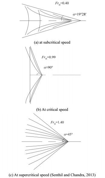
The critical condition occurs when FrH approaches or is equal to 1.00. At this point, the vessel reaches the critical speed, and the wave propagation angle (α in Fig. 1) approaches 90º and moves nearly perpendicularly to the vessel array. The wave patterns obtained at subcritical (FrH < 1.0), critical, and supercritical (FrH > 1.0) speeds are shown in Figs. 1(a)-(c). The wave pattern generated by vessel motion in calm water affects the resistance components, causing the resistance in shallow water to be larger than that in deep water at a similar speed. The ratio between the wave resistances in shallow water and deep water exceeds 15 at the critical speed and small water depth over vessel length, h/L, values (Faltinsen, 2005).
|
| Figure 1 Effect of shallow water on wave patterns |
The trim motion of HSCs in shallow water is an important consideration. Restricting the distance between the hull bottom and seabed changes the fluid velocity and pressure around the hull as shown in Fig. 2 and causes sinkage and large trims (Jachowski, 2008). The experimental work done by Kazerooni and Seif (2014) on the squats of the ship in shallow water conditions addressed the grounding risk due to the excessive hull sinkage for the limited underkeel clearance.

|
| Figure 2 Effects on limited depth on trim and sinkage |
These changes influence the resistance component of the vessel. The trim condition affects the flow on the hull surface and consequently changes the pressure distribution around it. In a previous analysis of the trim effect on the resistance of a semi-SWATH, the wave-making resistance was found to increase when the vessel is trimmed by stern at small-angle conditions rather than at even-keel conditions (Iakovatos et al., 2014). Each hull form is known to exert a specific response in terms of resistance due to the prevailing trim condition.
3 The experimental resistance test in shallow water conditionThe resistance of the semi-SWATH is predicted in experiments performed in shallow water. The resistance test is prepared according to ITTC standards but features several limitations because of differences in the performance of the semi-SWATH in comparison with those of other types of hulls in shallow water. Because of these limitations, some procedures including testing of the hull without fin stabilizers and testing of the hull with different water depths, were not performed to simplify the experiment. The attachment of the fin stabilizers to the hulls and the motion prediction system restrict the resistance test for hulls without the stabilizers. Excessive motion at smaller water depths can lead to grounding. The experimental results are analyzed based on the obtained resistance curves and wave heights.
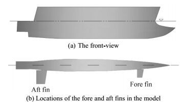
3.1 Effect of trim and sinkage on hull resistanceThe semi-SWATH model used in this study is shown in Fig. 3; the model features a fixed fin at the fore of the hull and an adjustable fin at its aft. Based on Rahimuddin (2013), this arrangement provides good seakeeping of the hull in calm water and wave conditions. The dimensions of the model are shown in Table 1 and main dimensions of fin stabilizer are in Table 2. The buoyancy of the hulls is provided by the submerged torpedo-like body below water surface.
|
| Figure 3 The illustration of the hull form of the semi-SWATH model |
| Particular | Full scale | Model |
| Overall length/m | 23.90 | 2.39 |
| Length of waterline, LWL/m | 21.11 | 2.11 |
| Overall breadth/m | 8.0 | 0.8 |
| Hull spacing between centerlines/m | 6.4 | 0.64 |
| Shallow water draft/m | 1.6 | 0.16 |
| Parameter | Fore | Aft |
| Length of span/m | 0.12 | 0.185 |
| Length of chord/m | 0.096 | 0.16 |
| Position from C.G./m | 0.7 | 0.924 |
| Aspect ratio | 1.25 | 1.15 |
The semi-SWATH model is tested in the Marine Technology Center of Universiti Teknologi Malaysia (MTC UTM). The tank size has been identified with the given dimension: length=120 m and width=4 m and the shallow water platform installed near the end of the towing tank is 18.75 m long. Such a length allows the vessel to reach steady-state conditions during testing. The model is tested at water depth-based scaled speeds ranging from about 0.94 to 1.74 m/s over FrH ranging from 0.65 to 1.2. During the tests, the separation distance between the demihulls is held constant at an S/L value of 0.30 according to the practical range for catamaran service, 0.20 < S/L < 0.40.
The water was considered shallow when the shallow water depth-to-draft ratio, h/T value was in the range of 1.2 to 1.5 (Vantorre, 2001). The water depth, h, in this experiment is 21.5 cm based on the range of h/T. The h/T value for this experiment is 1.35. The wave height generated by the semi-SWATH during operation is recorded according to the method applied in Ghani and Rahim (2008). Resistance and trim were recorded by a data acquisition and analysis system at the towing carriage. The measured total resistance is converted to the non-dimensional total resistance coefficient, CT, using Equation 4, and the residual resistant coefficient, Cr, is obtained from Eq. (5) by substituting the Cf value calculated by Eq. (6).
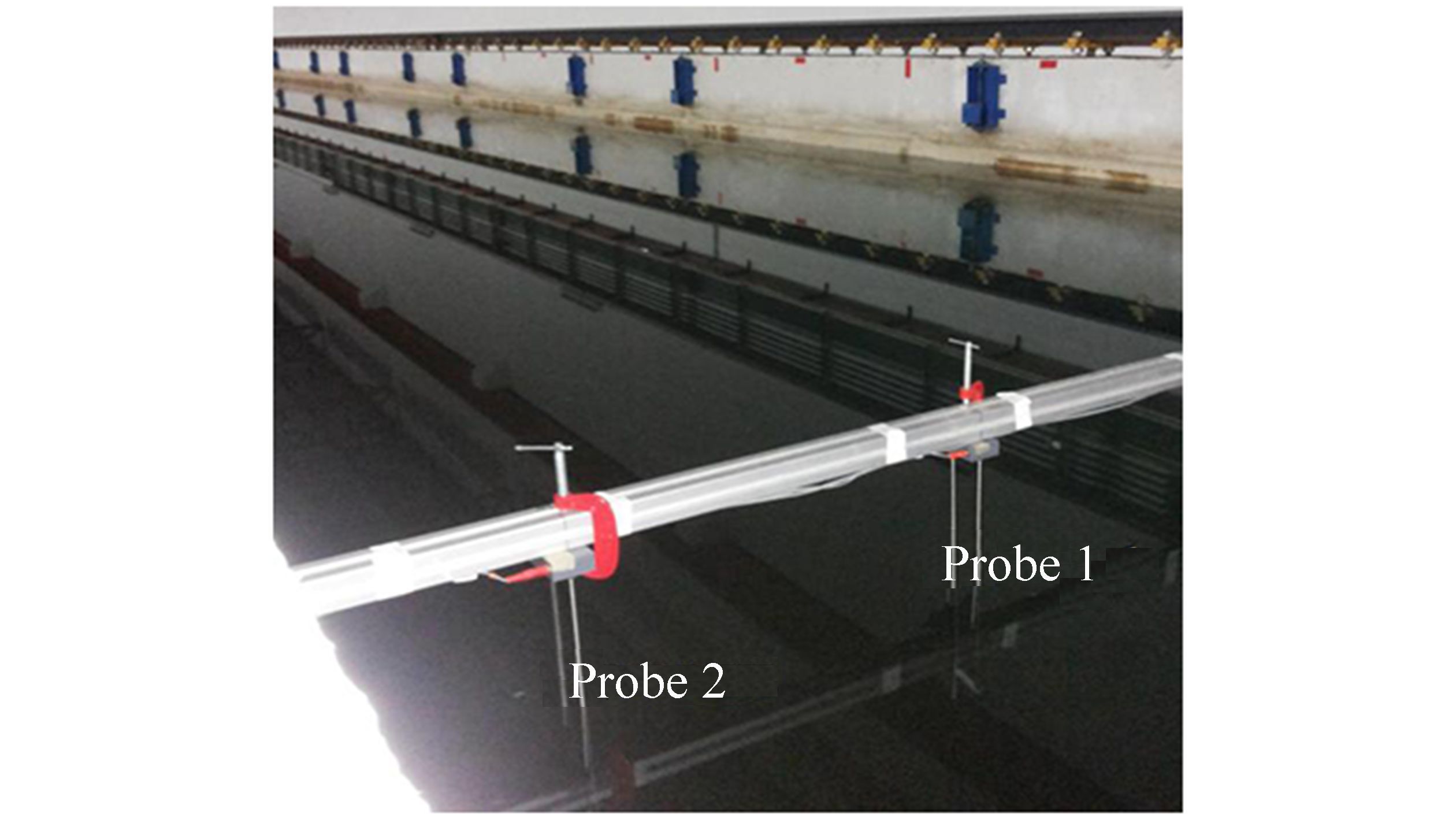
During the resistance test, characteristics of the wash generated by the hull is measured in terms of wave amplitude according to the method applied in Nasirudin (2007). Longitudinal wave cuts were measured by two wave probes with a specific y/L, as shown in Fig. 4, where y is the transverse distance of the probe from the tank centerline. Probe 1 measures near-field waves, while probe 2 measures far-field waves. Wave heights are recorded by LabView software integrated with the wave probes, a signal conditioning unit, and a computer.
|
| Figure 4 Installation of wave probes on the towing tank (y/L is 0.3 at probe 1 and 0.9 at probe 2) |
| ${C_{{T_m}}} = \frac{{{R_{{T_m}}}}}{{\frac{1}{2}\rho {U^2}A}}$ | (4) |
where ρ is the water density, U is the model speed, and A is the wetted surface area of the hull
| ${C_r} = {C_{{T_m}}} + {C_f}$ | (5) |
| ${C_f} = \frac{{0.075}}{{{{\left( {{{\log }_{10}}Re - 2} \right)}^2}}}$ | (6) |
where Re is the Reynolds number of the fluid
4 Results and discussionIn this work, the fin angles are varied to 0, 5, 10, and 15 degrees based on Fitriadhy (2007) who considered the effective fin angle for high speed to dynamic motion of the tested Semi SWATH.
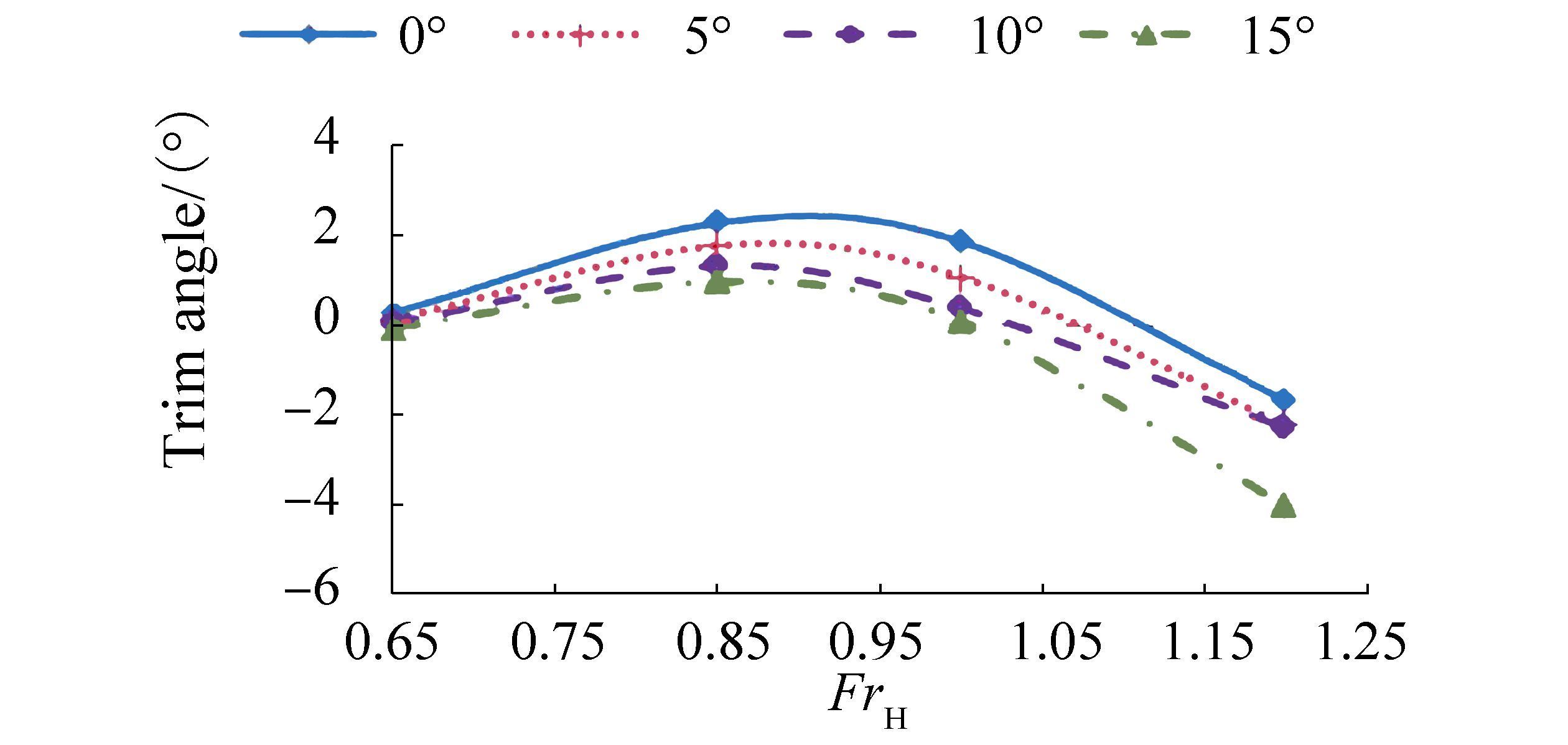
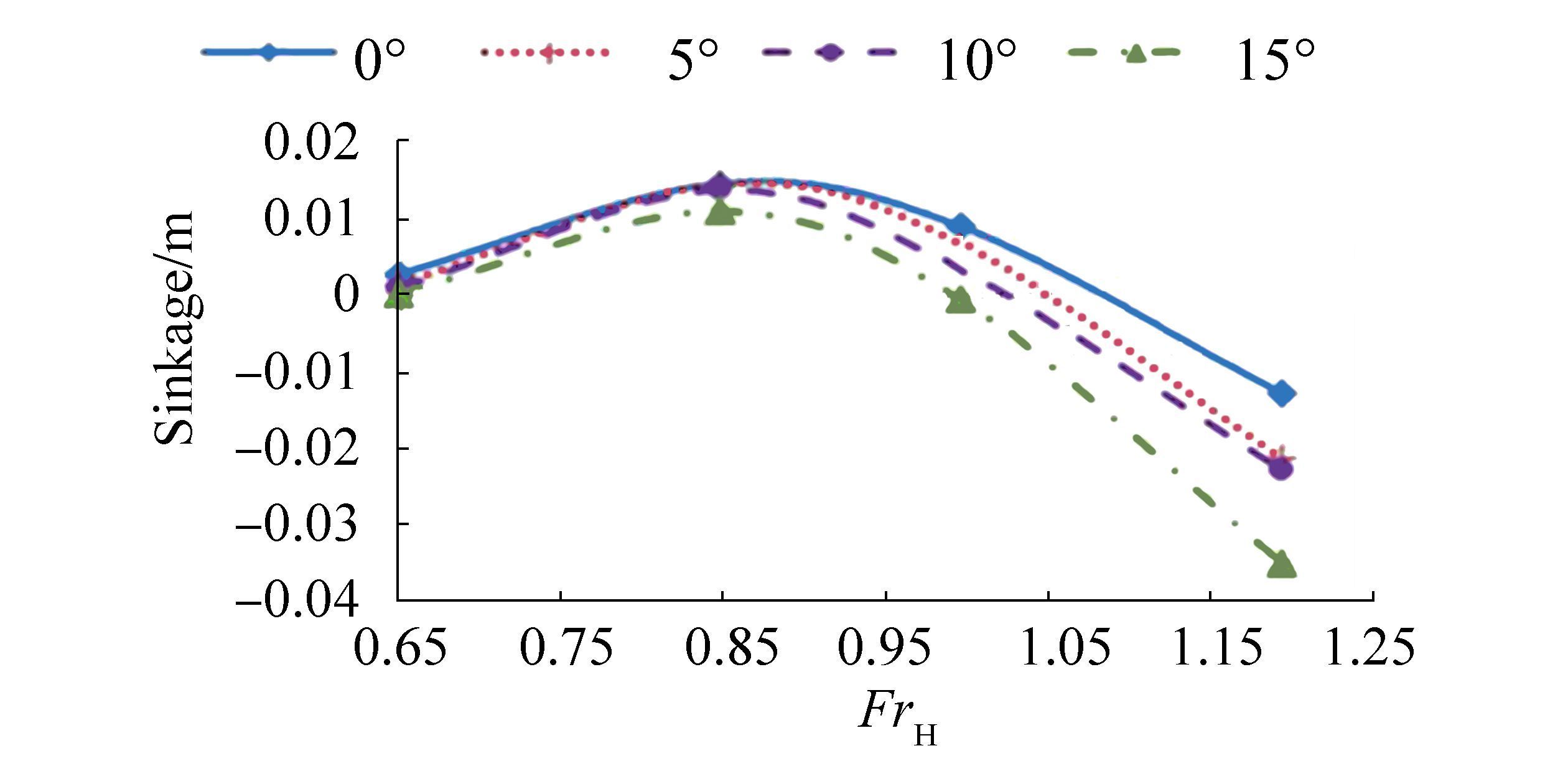
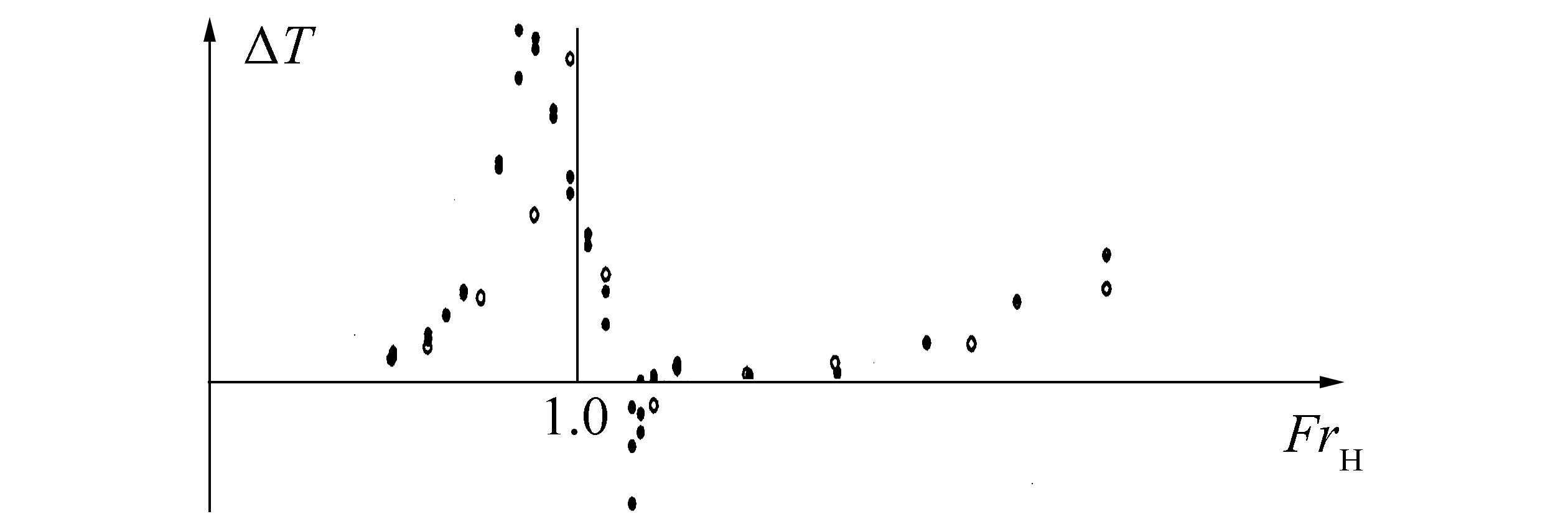
4.1 Trim and sinkage of the semi-swath in shallow waterFigs. 5 and 6 show the measured trim and sinkage at fin angles of 0º, 5º, 10º, and 15º. Validation of changes in the sinkage pattern of a vessel is important in shallow water analysis. Fig 6 shows that the sinkage pattern agrees with available results of SWATH sinkage in shallow water based on Bertram (1994). In this Fig. 7, the sinkage is represents by ∆T, and changes in the sinkage pattern between this work and the reference are compared for FrH < 1.2.
|
| Figure 5 The trim angle of the semi-SWATH in shallow water |
|
| Figure 6 Sinkage of the semi-SWATH in shallow water |
|
| Figure 7 Sinkage versus depth Froude number of a SWATH in shallow water obtained from Bertram (1994) |
The maximum trim and sinkage are obtained at high subcritical speeds over FrH values ranging from 0.8 to 1.0. The literature indicates that the sinkage reaches 0 at critical speed and becomes nearly constant after reaching a maximum value at supercritical speed. However, the sinkage of the semi-SWATH is not constant at supercritical speed, and values increase with increasing FrH. This result shows that the motion response of the semi-SWATH in shallow water differs from that of other vessels because of the effects of the fin stabilizer and hull form.
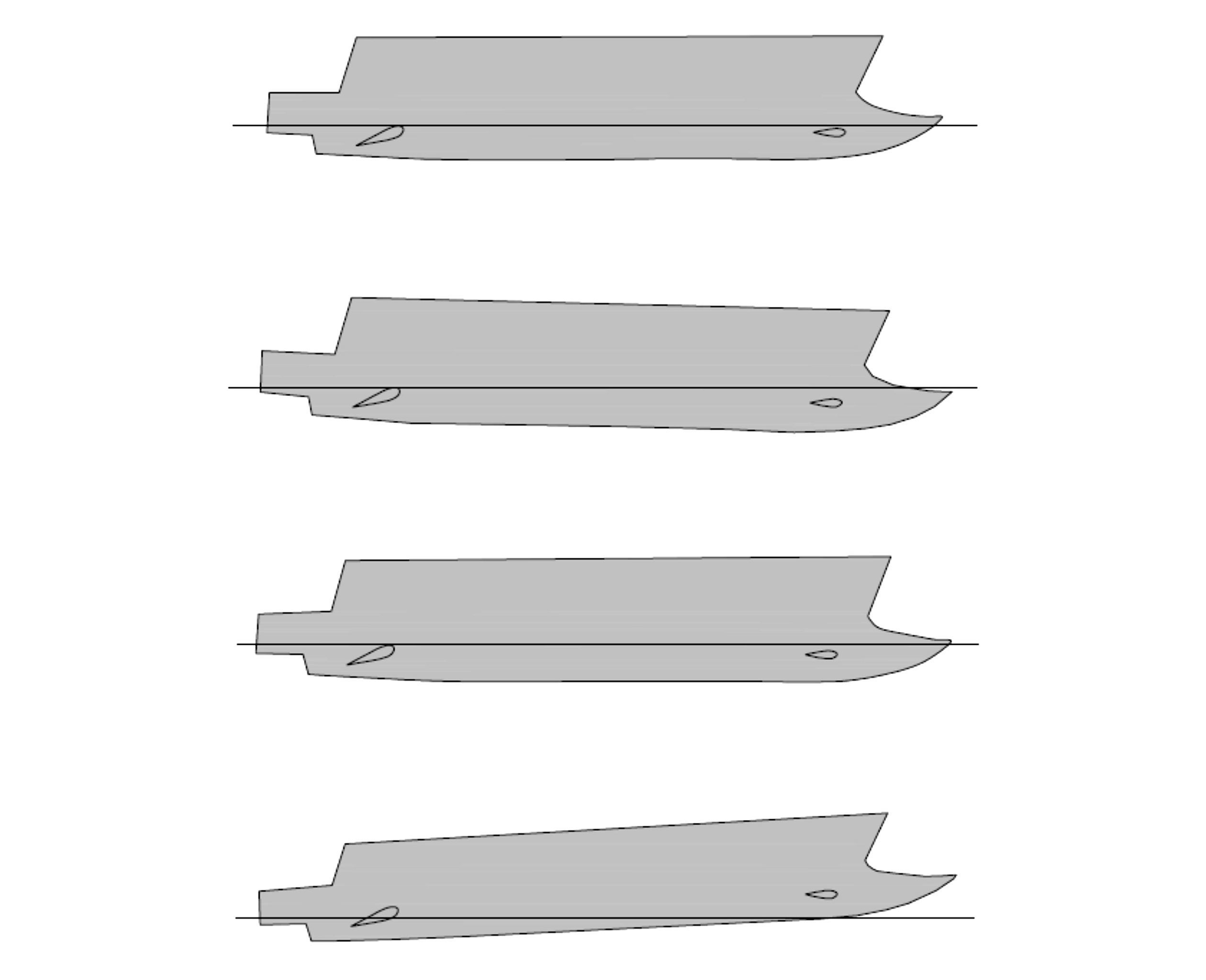
Fig. 8presents changes in the hull condition at each speed studied according to the measured trim angle and sinkage. The semi-SWATH tends to reach planning hull characteristics at high speed (Begovic, 2015), leading to a change in LwL/B value (Molland et al., 2008). The aft fin angle of 15º contributes to the most stable hull condition except at the supercritical speed, where the hull experiences large trim by stern.
|
| Figure 8 The hull conditions of the semi-SWATH with the aft fin angle of 15º at different speeds |
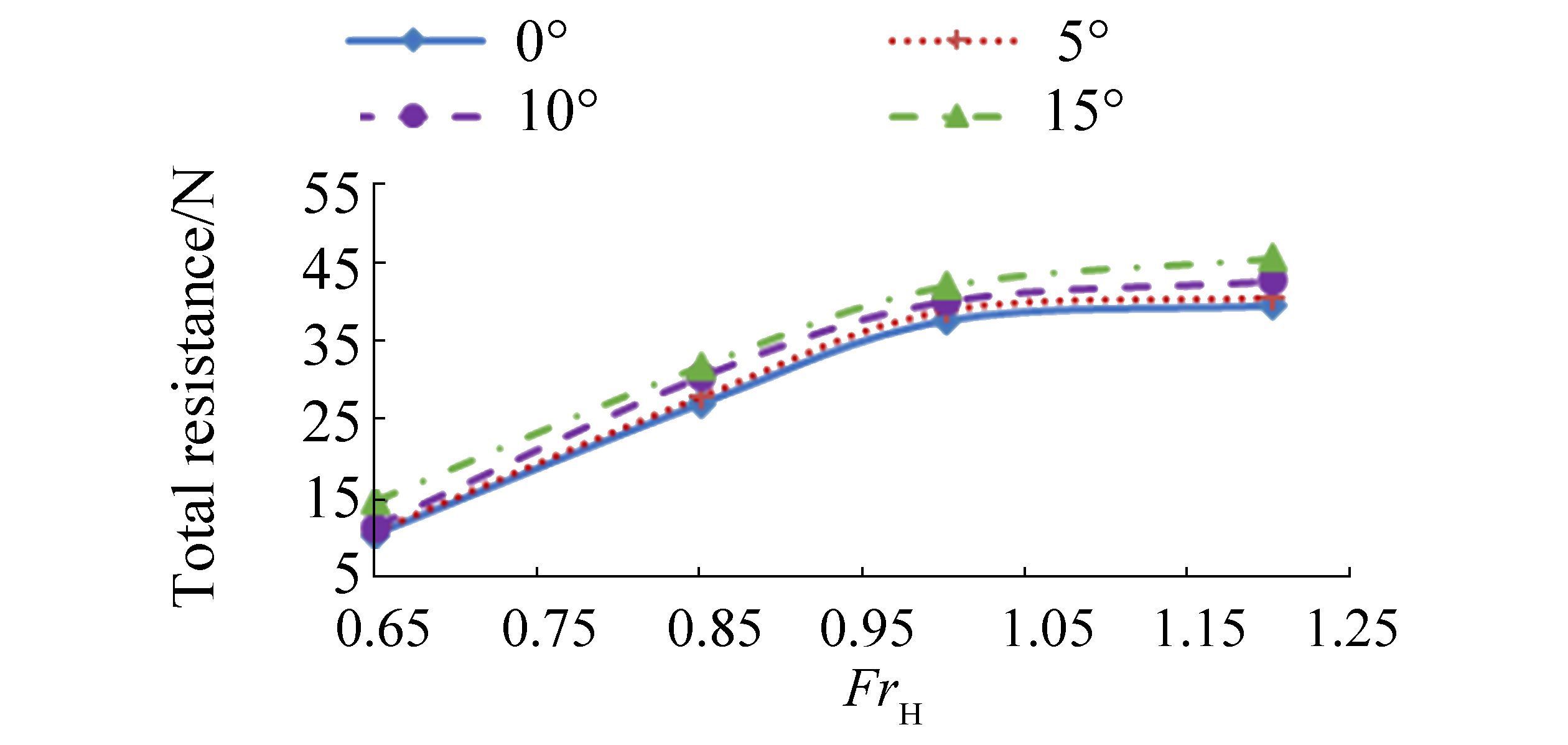
A comparison of the total resistance (RT) for each condition is shown in Fig. 9. Fins apparently exert different resistance effects over the range of Froude numbers investigated. At supercritical speed, where FrH is greater than 1.0, increases in resistance are less obvious than those at subcritical and critical speeds. The wave pattern changes, and no transverse waves exist at supercritical speed (Kirkegaard et al., 1998). Increases in aft fin angle lead to larger RT, which increases with 0.5-3.5 N increments for each 5-degree increase in fin angle. The resistance curve shows that resistance increases gradually with increasing Depth Froude number until a maximum point known as the hump speed at critical speed (FrH=1). Thereafter, the resistance becomes approximately constant with further increases in FrH. Small differences in resistance are also observed for each case at similar speeds.
|
| Figure 9 Resistance curve of the semi-SWATH in shallow water at different aft fin angles |
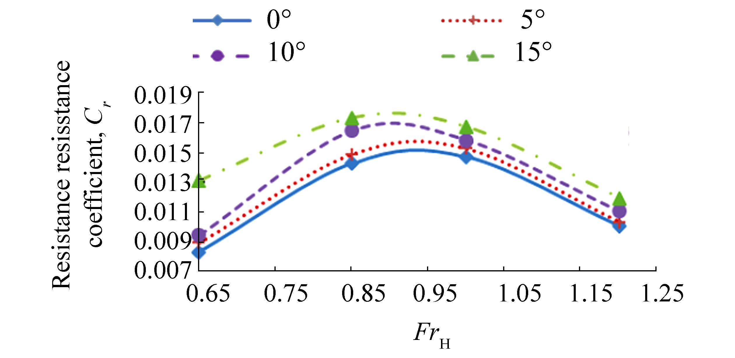
The residual resistance coefficient (Cr) of the semi-SWATH is calculated based on the measured total resistance and plotted in Fig. 10. The fin angle produces significant effects on changes in the hull resistance component with increasing Froude number. As the speed reaches the critical speed region, the hull produces the maximum Cr for each case; Cr values then decrease after the critical speed. This result reflects the significant effect of hull-generated waves at the critical speed region.
|
| Figure 10 Resistance curve of the semi-SWATH design in shallow water at different aft fin angles |
Changes in resistance can also be related to the sinkage and trim condition in shallow water. Variations in sinkage and trim conditions at different aft fin angles represent changes in the wetted surface area and immersed hull volume, which can affect the resistance components. The sinkage and trim condition also influence the pattern of flow through the bow of the hull and underkeel, further causing changes in the resistance components (Jurgens and Jager, 2006).
Differences in sinkage for each of the cases shown in Fig. 8reveal that changes in distance between the keel and seabed produce alterations in the physical characteristics of water flow and affect the pressure distribution on the hull. The aft fin angle exerts different effects on the trim and sinkage of the hull. Positive increases in fin angle produce larger lift forces and restoring moments, promoting better seakeeping criteria for the hull in shallow water. However, forces generated from large installation fin angles also increase the induced drag and consequently the resistance around the hull. This may be influenced by the pressure distribution on the surface of the foil (Liang et al., 2012).
4.3 Wave height of the semi-SWATH in shallow waterAs the wave pattern generated in shallow water influences the resistance of the semi-SWATH, the characteristics of waves generated from the vessel are analyzed. In this work, the wave pattern near the hull is highlighted because of the strong effect of near-field waves in this location.
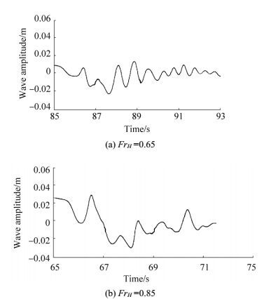
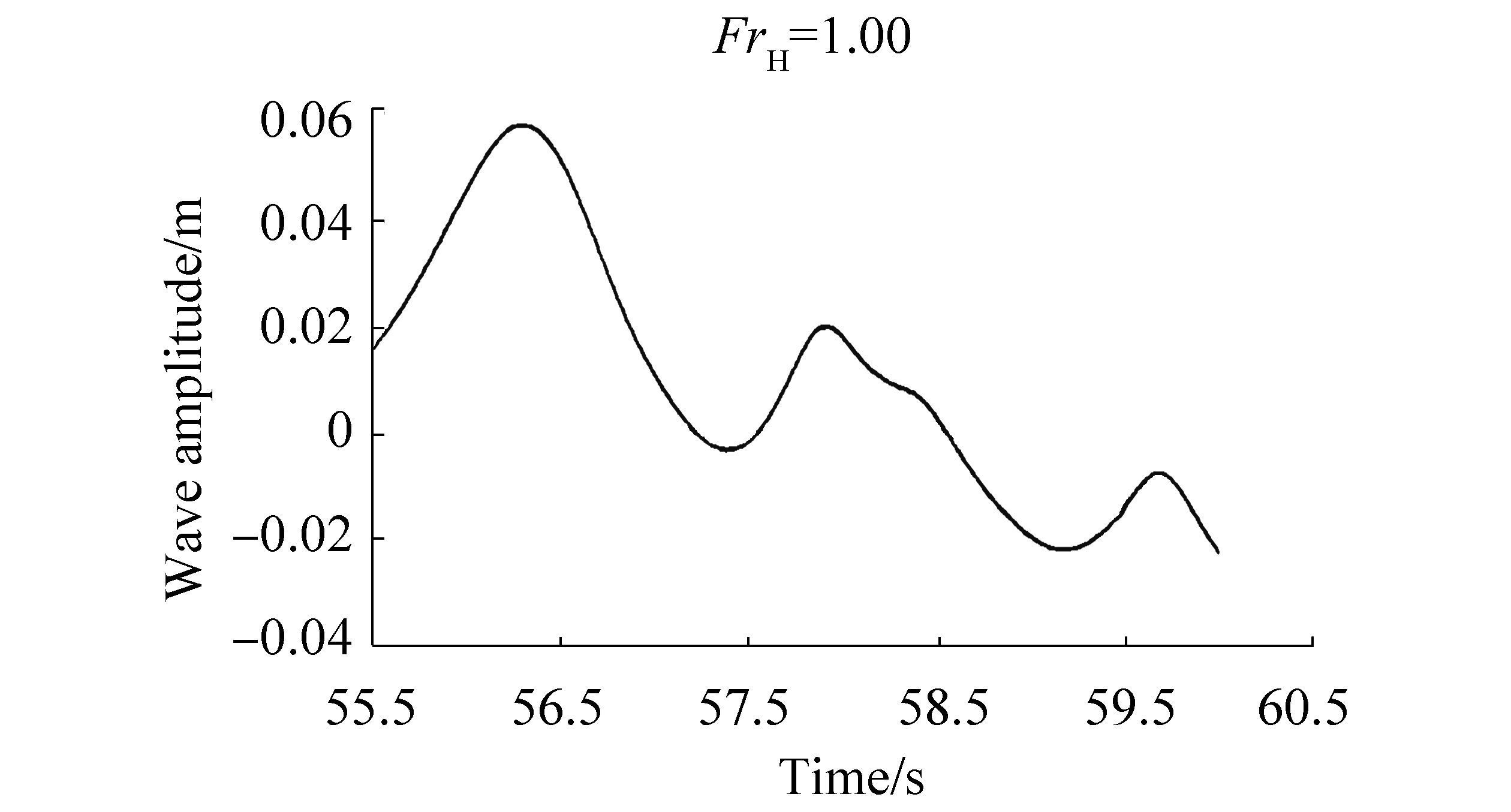
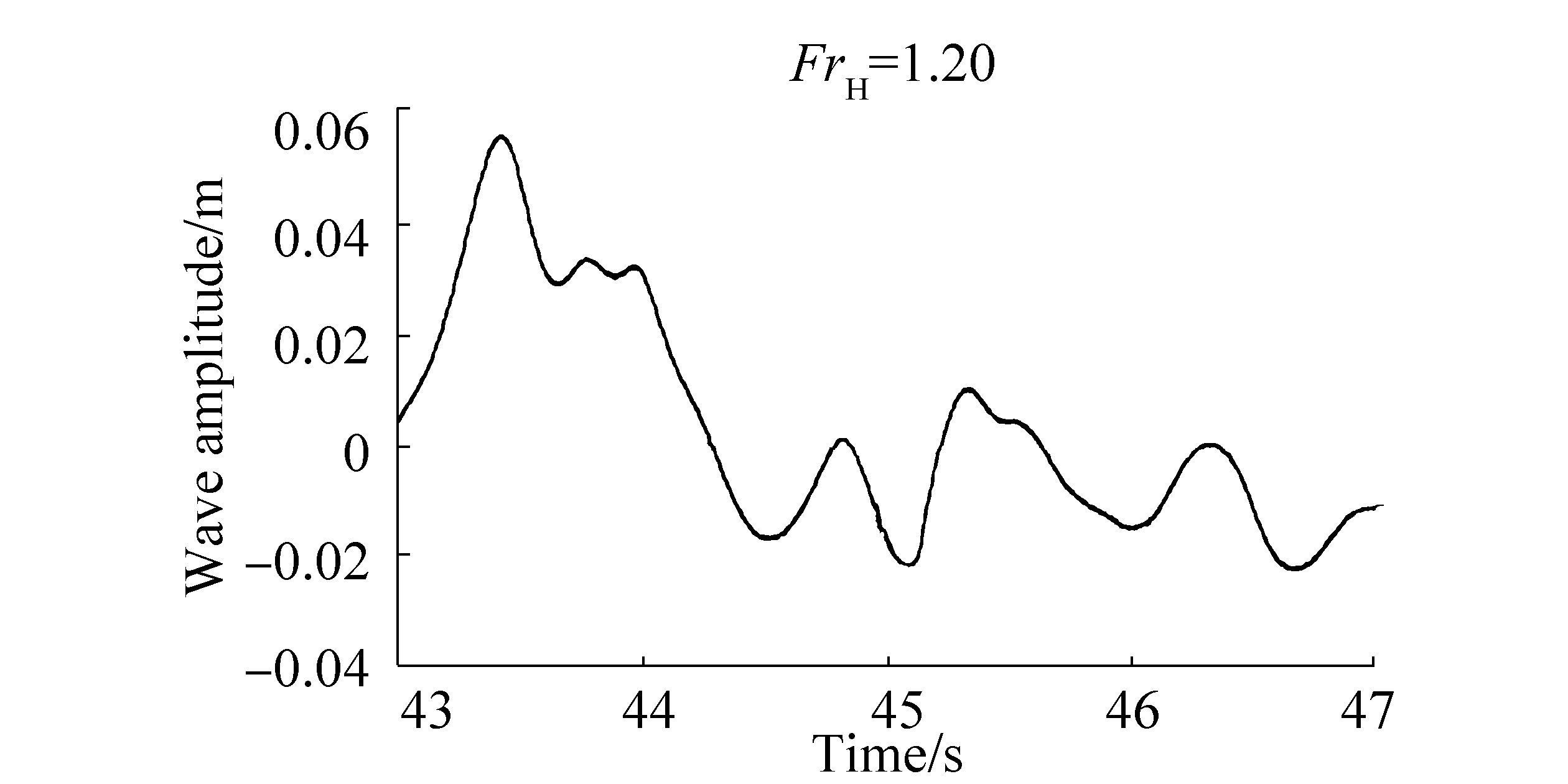
The wave patterns near the hull with aft fin 0º captured by wave probe 1 are shown in Figs. 11-13 with respect to its speed. The wave heights captured at the area around the hull and the region behind the hull stern are shown. The figures reveal that the wave pattern differs at every Depth Froude number. The wave period is large at subcritical speed and decreases at critical speed. The wave period begins to increase at supercritical speed. The sharp pattern of the wave amplitude curve at FrH =1.00 indicates the significance of wave formation at critical speed.
|
| Figure 11 Changes wave pattern captured by wave probe 1 at subcritical speed |
|
| Figure 12 Changes in wave pattern captured by wave probe 1 at critical speed |
|
| Figure 13 Changes in wave pattern captured by wave probe 1 at supercritical speed |
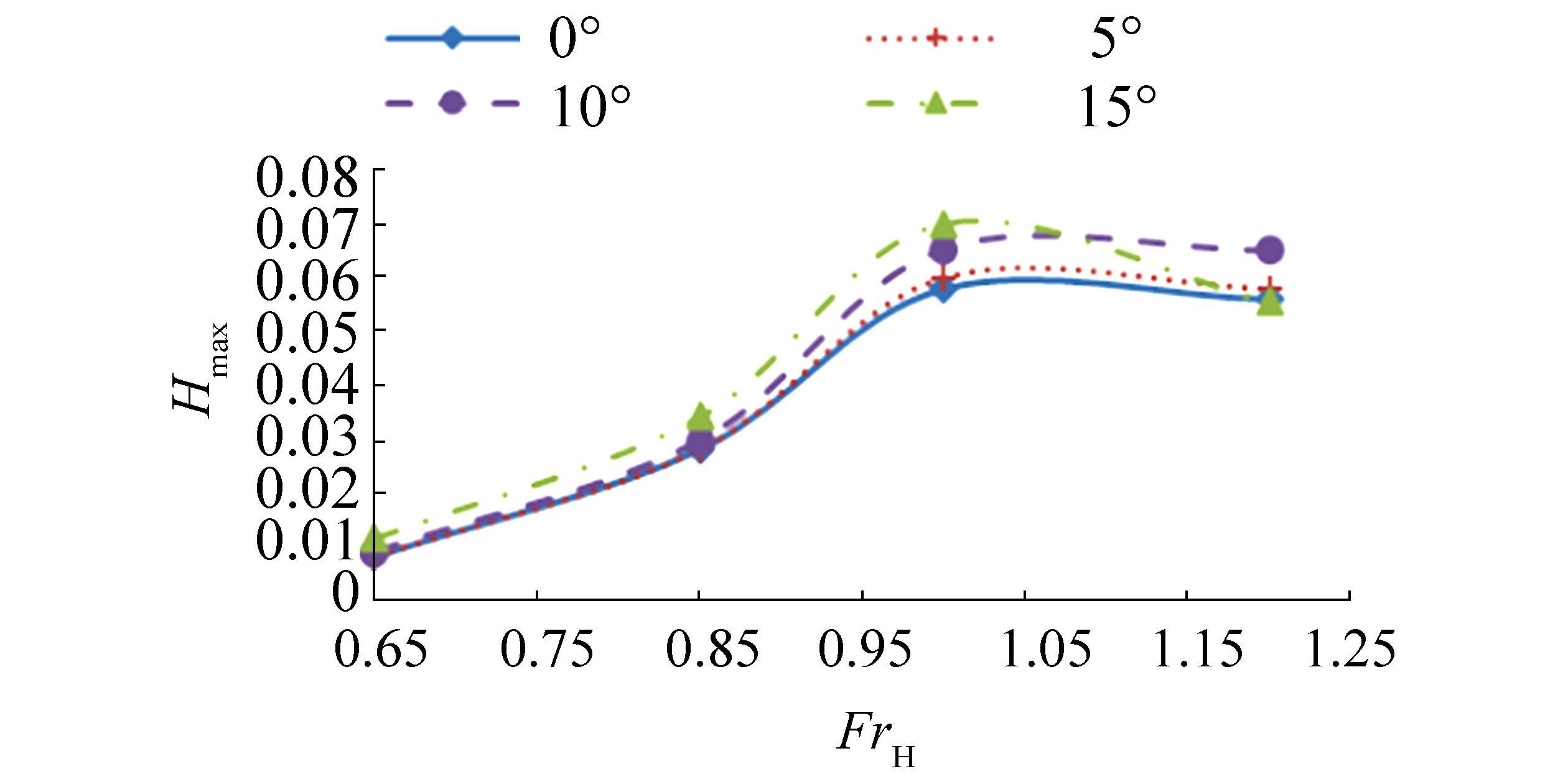
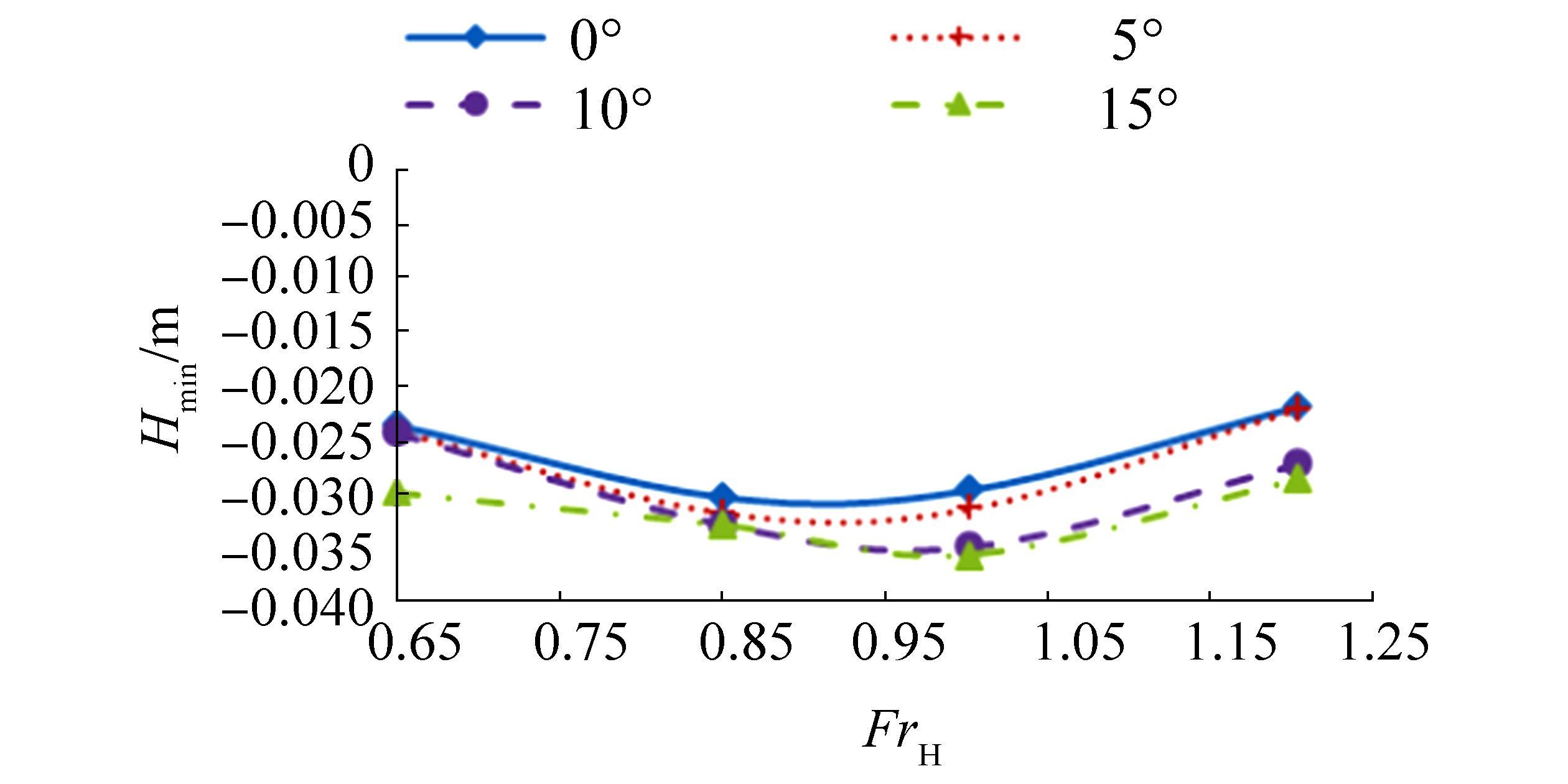
According to Ghani and Rahim (2008), wave patterns can be analyzed in terms of the maximum and minimum wave amplitudes over a range of positions around the hull. The maximum and minimum wave amplitudes detected by probe 1 were plotted against the Froude number and are presented in Figs. 14-15, respectively. Probe 1 indicates that waves are generated near field near the hull. In general, the maximum wave amplitude (Hmax) recorded at probe 1 is obtained at critical speed, and this value becomes constant at supercritical speed. The minimum wave amplitude (Hmin) increases until the critical speed and then decreases until the supercritical speed.
|
| Figure 14 Maximum wave amplitude recorded at probe 1 |
|
| Figure 15 Minimum wave amplitude recorded at probe 1 |
Changes in wave amplitude with speed can be affected by many factors. The effect of limited depths in shallow water strongly influences the pressure gradient and, consequently, the wave pattern generated around the hull. Changing the distance between the hull keel and seabed at different speeds alters the pressure around the hull, resulting in differences in the characteristics of the generated waves. The wave celerity significantly contributes to the changing of the wave pattern. At critical speed, the wave speed increases until the maximum celerity. Strong interference between the transverse waves generated by the vessel can occur at critical speed (Molland et al., 2008). Sufficient time is required for the wave energy to dissipate at critical speed if the strong wave interference effect persists (Glamore, 2005).
The fin stabilizer may be claimed to affect the maximum and minimum values of the wave amplitude. Although the changing patterns of the maximum and minimum wave amplitude are not perfectly similar between each case, the influence of fin angle on the pattern of generated waves can be predicted and analyzed. Under the condition of a 15-degree aft fin angle, Hmax is highest for both probes at subcritical and critical speeds. The Hmax is then reduced dramatically at supercritical speeds and becomes smaller than the Hmax of the semi-SWATH design with fin angles of 5º and 10º. Similar to the maximum amplitude, the Hmin at probe 1 is highest for the waves generated by the semi-SWATH design with a 15-degrees aft fin angle.
Comparison of the resistance and both Hmax and Hmin of the hull at different fin angles is beneficial to predict the factors contributing to the total resistance. The fin stabilizer influences the total resistance in term of the generated waves and the induced drag, which similar with the result of Chen (2013). The pressure point of the hulls is shifted due to the existence of fins that alters the wave systems based on the angle configuration (Ram et al., 2014). Furthermore, the induced drag from the fin stabilizer is dependent on the angle of attack, which is according to the ship's initial pitch angle and the relative fluid velocity with respect to the fin stabilizer (Radhakrishnan et al., 2011).
Wave energy can be related to the amplitude of waves generated from the hull (Molland et al., 2008). The high resistance observed in the case of the 15-degree aft fin angle is contributed by the energy produced from wave formation around the hull and fins at subcritical and critical speeds, where transverse and divergent waves present high amplitude. At supercritical speed, the generated wave pattern is not the dominant factor contributing to high resistance. The phenomena of supercritical speed are not fully achieved by semi-SWATH at FrH=1.20 compared to theory due to the low dissipation of transverse wave energy. This gives effect on the hull resistance at supercritical speeds as well as the planing hull condition.
5 ConclusionsResistance tests of a semi-SWATH design in shallow water is performed to achieve the shallow water resistance and wave pattern of semi-SWATH with effect of FrH and fin stabilizer. The fin stabilizer affects the Semi SWATH resistance by 1) changing of trim condition and 2) changing of the induced resistance by the fins according to the hull trim condition. The Hmax and Hmin of the hull reaches maximum values at a critical speed, and FrH =1.0 for most of the cases studied. These values are reduced at supercritical speeds. The results are in agreement with shallow water theory as the wave in supercritical speeds is affected only by divergent waves and effects on hull resistance are reduced.
The effects of fin angle on the resistance, trim, sinkage, and wave generation of the semi-SWATH are defined. Changes in sinkage and trim angle are reduced by increasing the fin angle except at supercritical speed. Trim changes at supercritical speed cause increases in resistance. Similar to the total resistance, the amplitude of waves generated be the semi-SWATH also increases with increasing fin angle. The fin angle and significant trim and sinkage of the hull contribute to increases in semi-SWATH resistance in restricted water depths.
Further research on fin stabilizer designs must be carried out to investigate wave interference phenomena between the fin and hull. Studies in this field could include prediction of the wave interference factor to determine its relation to wave height and performance of the shallow water resistance test at different h/T.
Acknowledgement:The authors would like to express their appreciation for the technical support from staff of MTC UTM, Faculty of Mechanical Engineering, UTM.
| Begovic E, Bertorello C, Mancini S, 2015. Hydrodynamic performances of small size SWATH. Shipbuilding, 66(4), 1–22. |
| Bertram V, 1994. Shallow water effects for SWATH ships. 9th International Workshop Water Waves and Floating Bodies, Kuju, 21-25. |
| Brizzolara S, Bruzzone D, 2003. Near and distant waves of fast ships in unlimited and limited depths. Proceedings of the 7th International Conference on Fast Sea Transportation, Ischia, 3, H1-H13. |
| Chen SL, 2013. Hydrodynamic behaviour of gliding hydrofoil crafts. PhD thesis, City University London, London, 159-161. |
| Couser PR, Molland AF, Armstrong N, Utama KAP, 1997. Calm water powering predictions for high speed catamarans. FAST 1997 The 4th International Conference on Fast Sea Transportation, Sydney, 765-774. |
| Faltinsen OM, 2005. Hydrodynamics of high speed marine vehicles. Cambridge, United Kingdom: Cambridge University Press165-220. |
| Fitriadhy A, 2007. Seakeeping evaluation of semi-SWATHvessel in head-seas using time domain simulation. Master thesis, Universiti Teknologi Malaysia, Malaysia, 99-108. |
| Ghani MPA, Rahim MNA, 2008. The prediction of wake wash in the towing tank. Jurnal Mekanikal, 26, 129–140. |
| Glamore WC, 2005. A decision support tool for assessing the impact of boat wake waves on inland waterways. PIANC Magazine on Course, Belgium, 133, 5–18. |
| Iakovatos M, Liarokapis D, Tzabiras G, 2014. Experimental investigation of the trim influence on the resistance characteristics of five ship models. In: Guedes Soares C and Pena FL (Eds. ). Developments in Maritime Transportation and Exploitation of Sea Resources, CRC Press, 23-28. |
| Insel M, Molland AF, 1991. An investigation into the resistance components of high-speed displacement catamarans. Proceedings of the Meeting of the Royal Institutions of Naval Architects (RINA), London. |
| Jachowski J, 2008. Assessment of Ship Squat in Shallow Water using CFD. Archives of Civil and Mechanical Engineering, 8(1), 27–36. DOI:10.1016/S1644-9665(12)60264-7 |
| Jurgens AJ, Jager D, 2006. Controllability at too high speeds in too shallow water. Proceedings of the 26th MARSIM International Conference on Marine Simulation and Ship Manoeuvrability, Netherlands, M22, 393-404. |
| Kazerooni MF, Seif MS, 2014. Experimental study of a tanker ship squat in shallow water. Jurnal Teknologi (Sciences and Engineering), 66(2), 15–20. DOI:10.11113/jt.v66.2477 |
| Kirkegaard J, Kofoed-hansen H, Elfrink B, 1998. Wake wash of high-speed craft in coastal areas. Coastal Engineering, 325–337. DOI:10.9753/icce.v26.%25p |
| Liang L, Wang B, Ji M, 2012. Adaptive fuzzy control for SWATH ship seakeeping characteristics. Proceedings of the IEEE International Conference on Mechatronics and Automation, ICMA 2012, Chengdu, 440-445. |
| Millward A, 1996. A review of the prediction of squat in shallow water. Journal of Navigation, 49(1), 77–88. DOI:10.1017/S0373463300013126 |
| Molland AF, Bertram V, Carlton J, 2008. Powering. In: Anthony F. Molland (Ed. ). The Maritime Engineering Reference Book, Oxford, 182-343. |
| Molland AF, Wilson PA, Taunton DJ, 2003. Resistance experiments on a systematic series of high speed displacement monohull and catamaran forms in shallow water. Ship Science ReportNo. 127, University of Southampton. |
| Mousaviraad SM, Wang Z, Stern F, 2015. URANS studies of hydrodynamic performance and slamming loads on high-speed planing hulls in calm water and waves for deep and shallow conditions. Physics Procedia, 51, 222–240. DOI:10.1016/j.apor.2015.04.007 |
| Nasirudin A, 2007. Parametric study of low wake catamaran hull form. Master thesis, Universiti Teknologi Malaysia, 14-22. |
| Radhakrishnan S, Vengadesan S, Idichandy V, 2011. Numerical simulation of a fin at varying angle of attack. World Academy of Science, Engineering and Technology, 776-783. |
| Rahimuddin, 2013. Seakeeping performance of semi-SWATH ship in following sea using controlled fins stabilizer. PhD thesis, Universiti Teknologi Malaysia, Malaysia, 87-117. |
| Ram BRR, Surendran S, Lee SK, 2014. Computer and experimental simulations on the fin effect on ship resistance. Ships and Offshore Structures, 10(2), 122–131. DOI:10.1080/17445302.2014.918308 |
| Sahoo PK, Doctors LJ, 2003. A study on wave resistance of high-speed displacement hull forms in restricted depth. Proceedings of the 7th International Conference on Fast Sea Transportation, Ischia, 25-32. |
| Senthil PMN, Chandra B, 2013. Numerical estimation of shallow water resistance of a river-sea ship using CFD. International Journal of Computer Application, 71(5), 33–40. DOI:10.5120/12357-8670 |
| Stumbo S, Fox K, Elliott L, 1999. Hull form considerations in the design of low wake wash catamarans. Proceedings of the Fifth International Conference on Fast Sea Transportation, Seattle, 83-90. |
| Vantorre M, 2001. Manoevring coefficient for a container carrier in shallow water: An evaluation of semi empirical formulae. Proceedings of Mini Symposium on Prediction of Ship Manoeuvring Performance, Tokyo, 71-81. |
| Whittaker TJT, Doyle R, 2001. An experimental investigation of the physical characteristics of fast ferry wash. Proceeding of HIPER'01: 2nd International EuroConference on High-Performance Marine Vehicles, Hamburg, 480-491. |


