2. Faculty of Maritime Studies, University of Split, Split 21000, Croatia
1 Introduction
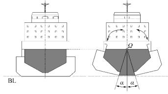
Trailing Suction Hopper Dredgers (TSHD) are working ships that are used mainly for excavating large amounts of grabbed material from the seafloor and transporting them to other locations at sea. In recent years, a special type of dredger called Split TSHD with variable geometry that can split in two to open the cargo hold has been developed. The main goal of such a ship is fast cargo discharge at certain nearshore sea positions by using gravitational force or mass flow from silo-shaped cargo holds, Fig. 1. The entire hull opens by using a hydraulic system, with theoretically symmetric variable geometry different from initial ship geometry. However, opening failures can occur, producing non-symmetric ship geometry and potentially high stability risk that should be assessed.
|
| Figure 1 Split TSHD main frame section with split hulls in discharge condition rotated around joint Ω |
Nevertheless, usual hydrostatic and stability calculations are conducted for initial, non-variable hull geometries only owing to the complexity of such calculations when using current calculation methods based on numerical procedures and non-analytical geometry descriptions. Moreover, current stability regulations regarding Split TSHD (Bureau Veritas, 2004a, 2014b), Rules for classification of steel ships: Dredgers, Loading conditions, and Ships for dredging activity, Intact Stability, November, 2004 edition, and IMO Circ. 2285, 2001) cover initial loading conditions only, thus avoiding calculations of hydrostatic particulars for intermediate ship positions.
In case of the split TSHD, where the ship's hull splits into two to discharge cargo, hydrostatic properties are calculated for the initial hull geometry only, without covering intermediate loading conditions, owing to numerical calculation complexities connected with the need for defining variable ship geometry for each new split angle and the need for calculating the associated hydrostatic particulars repeatedly.
While a new geometry position/configuration is easy to define using affine transformation, that is, rotation around a joint point, as in Fig. 1, numerical integration can be more complex and demanding if Simpson rules are used. Although the trapezoidal rule makes calculation easier, the calculations are still exhaustive and time consuming, and are therefore not performed in practice.
The only efficient solution for the abovementioned ship geometry variations is the use of analytical geometry description methods, as will be described further, where geometry calculations are performed only once for the initial ship geometry, and Boolean geometrical algebra and affine transformations are used subsequently for calculating the hydrostatic particulars associated with changes in ship geometry. An analytic solution of ship geometry description based on Polynomial Radial Basis Function (PRBF) (Ban et al., 2014) is used in this paper, as described in Chapters 2 and 4, as opposed to the numerical calculations used by Dehghan et al. (2014), Dehghan and Shokri (2008), Dehghan and Nikpour (2013), and Dehghan and Mohammadi (2015) for solving various problems of applied mathematics and physics. In that way, the calculation of hydrostatic particulars for arbitrary list angles is made possible based on the work of Ban and Bašić (2015) and Ban (2012), thus enabling hull affine geometry transformations using rotation as well.
Moreover, all of a ship's theoretical hydrostatic particulars will be precalculated for all compartments and for all possible loading conditions containing three degrees of freedom of quasi-static ship, draught, angle of trim, and list angle, as given in Chapter 3. Thus, a type of extreme learning machine is obtained, as described in Sajjadi et al. (2016), leading to a novel calculation strategy for naval architecture applications with the possibility of using parallel calculations and computer clusters and clouds, as in Shojafar et al. (2016) and Jahangirzadeh et al. (2016).
Instead of the entire ship, test results will be given for a 2D ship section of a Split TSHD to simplify the calculations without loss of generality. The global non-two manifold description method for 2D geometry, based on the composition of linear and cubic polynomial radial basis functions, will be used to facilitate simultaneous description of flat and smooth curve parts. To define all ship compartments for initial ship geometry, in Chapter 4, basic parts will be defined using the Boundary representation (B-rep) method, with Boolean geometric algebra summation and subtraction used for their creation.
Both symmetric and non-symmetric geometry cases will be solved in this paper, thus enabling complete calculation of the hydrostatic particulars of Split TSHD ships. To calculate the hydrostatic particulars of angled ships, non-symmetric compartments need to be calculated for negative and positive list angles, for all ship positions, as shown in Chapter 5. Therefore, the division of Split TSHD geometry into outer and inner compartments needs to be extended to division in terms of variation in symmetry and geometry. This implies that every compartment will be calculated using different procedure regarding symmetry and variability. Thereafter, ship compartments can be split in two to obtain intermediate loading conditions for Split TSHD by using affine transformation on rotation as rotation about splitting point.
The cargo hold of a Split TSHD is of the open type, that is, it does not have a top, and it has a hold overflow pipe to ensure that the maximum cargo load is not exceeded.
Since ship geometry is calculated analytically, the geometric and hydrostatic properties of ship compartments can also be calculated using geometric algebra, together with affine rotation transformation, thus allowing for calculation of all required Split TSHD loading conditions. Moreover, calculation of all hydrostatic particulars of split hulls will be performed based only on previously calculated initial geometry calculations by using coordinate system relationships for angles and distances. Thus, no additional geometry calculations will be needed, with calculation of all hydrostatic particulars for split hulls from the initial, precalculated hydrostatic values, as shown in Chapter 6.
To display the overall characteristics of hydrostatic properties calculations for variable geometry, we will present the results of a typical test ship with a constant transverse section, that is, we will calculate the hydrostatic particulars of a theoretical Split TSHD barge with symmetric hull opening, in Chapter 7.
2 Polynomial radial basis functions 2.1 Radial basis function definitionPRBF have been developed recently to provide accurate analytical description of 2D ship geometry in order to directly solve the hydrostatic integrals associated with arbitrary list angles. Ban et al. (2014) showed that 2D ship geometry with discontinuities can be described using a composition of cubic and linear PRBFs, thus enabling further solution of five basic ship hydrostatic integrals (Ban and Bašić, 2015) necessary for further stability calculations. Moreover, the respective solutions of ship hydrostatic integrals for arbitrary ship list angled are given in Ban (2012), which facilitates calculation of hydrostatic properties for all ship positions and affine geometric transformations.
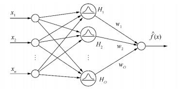
Theoretically, RBFs provide direct solution of the scattered data interpolation problem (Shepard, 1968). They are usually used in direct feed-forward neural networks, Fig. 2, but they are the basis of meshless methods as well because their use does not warrant mesh organization of their input X≡ {xj, j = 1, …, N} and output training data Y ≡ {xj, j = 1, …, N}. Their applicability to 2D ship geometry description using global interpolation was explored by Ban et al. (2010), where MQ RBFs were found useful. We are interested in basis functions f: Ω → IR defined on some region Ω ⊆ IRd, where d is dimension of a problem.
|
| Figure 2 Single-layer feed-forward RBF neural network |
In general, RBFs can be described as weighted sums of basis functions translated around points ti called centers, whose number depends on the mathematical procedure chosen for object representation. Mathematically, a RBF network as a linear combination of certain basis functions is defined as
| $ \mathit{\boldsymbol{y}}=f\left( \mathit{\boldsymbol{x}} \right)=\sum\limits_{i=1}^{O}{{{w}_{i}}{{\mathit{\Phi }}_{i}}\left( \left\| x,{{t}_{i}} \right\|,c \right),\ \mathit{\boldsymbol{x}}\in \mathit{\Omega }\subseteq \rm{I}{{\rm{R}}^{d}},\ \mathit{\boldsymbol{y}}\in \rm{I}{{\rm{R}}^{l}}} $ | (1) |
where {xj}, j = 1, …, N; x ∈ IRd is the input data set; {Bi} denotes basis functions; {Φi} denotes RBFs; {ti} denotes RBF development centers with i = 1, …, N, where O is the number of centers, {wi} denotes RBF network weight coefficients, ϕ denotes RBFs based on the Euclidian norm L2 between input data and centers, c is a shape parameter, and f(x) is a generalized interpolation/approximation function.
The main advantage of RBFs is that they offer a solution to scattered data interpolation problems via determination of the weight coefficient vector/matrix w using inversion of the interpolating matrix H as follows:
| $ \mathit{\boldsymbol{w}}={{\mathit{\boldsymbol{H}}}^{-1}}\cdot y $ | (2) |
where w ={wi} is weight coefficient matrix/vector; H = [Hji] is the interpolating matrix with elements Hji=║xj-ti║; y = {yj}∈ IRd is the output data set with j = 1, …, N, for the related input data set x = {xj}, j = 1, …, N; and d is the dimensionality of the problem.
Naturally, in the interpolation case, the center points t coincide with the input points x, where the number of centers O is equal to the number of input points N.
2.2 PRBF definitionStandard RBFs with the L2 norm ensure positive definiteness and invertibility of the interpolation matrix H. As mentioned before, the above can be achieved by squaring only the L2 norm. But this also leads to occurrence of the fill distance limitation hX, Ω between points in an arrangement of data site points. By contrast, when RBFs with the L1 norm are used, the fill distance limitation between points hX, Ω does not exist, and
| $ {{h}_{X,\mathsf{\Omega }}}\to 0 $ | (3) |
This means that data site X can be chosen freely for description of some arbitrary geometry with discontinuities, as described in Ban and Ljubenkov (2015), with denser description near discontinuities. This is one of the main reasons why RBFs with the L1 norm should be used, in addition to the possibility of obtaining RBFs in polynomial form.
For 2D problems, PRBFs with the L1 norm are generally defined as:
| $ f\left( r \right)=\sum\limits_{i=1}^{N}{{{w}_{i}}\left( {{\left| \mathsf{x}-{{\text{t}}_{i}} \right|}^{\beta }}+c \right),\beta \in \text{IR}\backslash 2\cdot \text{IN}} $ | (4) |
with the shape parameter c ∈ IR set outside radial basis function exponent β, with function exponent β defined in the entire space, real numbers IR restricted to even integers, and r = |x–ti|.
Ban et al. (2014) showed that PRBFs can be used to provide global analytical descriptions of a curve with discontinuities, that is, a composition of linear and cubic PRBFs with dense distribution of points around discontinuities is the exact solution of one-dimensional discontinuity description problem with
| $ f\left( r \right)=\sum\limits_{i=1}^{N}{{{w}_{i}}\left( {{\left| x-{{t}_{i}} \right|}^{3}}+c \right)}+\sum\limits_{l=1}^{L}{{{w}_{l}}\left| x-{{\text{t}}_{i}} \right|} $ | (5) |
where i = 1, …, N + D are points of the input data set, with N initial number of points and D added points around discontinuity, l = 1, …, L are the discontinuity points, and c is shape parameter for cubic PRBFs.
Because the shape parameter c is set outside of the basis function bracket, a symmetric interpolation matrix H is obtained, thus eliminating the problem of inversion of the interpolating matrix, which is typically encountered for RBFs defined with the L2 norm.
It can be concluded that the integer exponent values β become acceptable for PRBFs because they have the L1 norm, thus avoiding squaring of the norm, as is the case with standard RBF definitions based on the L2 norm, directed by Schoenberg-Menger's theorem for conditionally positive semi-definite matrices (Fasshauer, 2007) similar to MQ RBFs.
3 Calculation of ship hydrostatic particulars 3.1 GeneralThe main advantage of polynomial RBFs over other description methods is the possibility of analytical description of curve discontinuities, as described in Ban et al. (2014), in contrast to that with typical numerical methods. After the geometry is described globally using a composition of cubic and linear PRBFs, as shown in Ban et al. (2014), ship hydrostatic particulars can be calculated directly, together with the associated particulars for angled ships, as shown in Ban and Bašić (2015) and Ban (2012). Thus, complete ship hydrostatic particulars for outer and inner ship geometry can be calculated, covering the entire required ranges of drafts d and list angles φ. In that way, the usual theoretical hydrostatic particulars calculations performed for different trim values can be extended for the entire range of list angles φ, giving all necessary ship's hydrostatic particulars for further stability and other theoretical calculations. In the case of Split TSHD, it means that we will be able to calculate intermediate loading conditions during cargo unloading.
The ship waterline particulars and the associated integrals to be determined are
--Waterplane area AWL,
--Centroid of waterplane area XWL≡{xWL, yWL}, and
--Moment of inertia of waterplane IWL≡{IL, IB}.
Displacement particulars and their belonging integrals are:
--Volume of displacement ∇, and
--Centre of buoyancy XB≡{xB, yB, zB}.
After obtaining the results of the frame section areas and the associated static moments around the y-axis, it is necessary to integrate along the remaining x-axis to obtain the following ship displacement particulars values:
--Section area A
--Section area moment around y axis, My.
To calculate the center of waterline area for all ship list angles, it is necessary to determine the associated area moments as
| $ {{M}_{WL}}={{A}_{WL}}\cdot {{X}_{WL}},\ \ \ \ \ \ \ \ \ \ {{M}_{WL}}\{{{M}_{WL,x}},{{M}_{WL,y}}\} $ |
The respective displacement volume moments for calculation of the center of buoyancy are
| $ {{M}_{B}}=\nabla \cdot {{X}_{B}},\ \ \ \ \ \ \ \ \ \ {{M}_{B}}\equiv \{{{M}_{B,x}},{{M}_{B,y}}\} $ |
Finally, the positions of ship metacentres have to be calculated. In the case of slender bodies, as modern ships usually are, metacentre values differ largely in the longitudinal and the transverse directions, that is, motions are not coupled. So their values have to be calculated as
--Longitudinal metacentre XWL≡{xWL, yG, zML}
--Transverse metacentre XMB≡{xG, yMB, zMB}.
3.2 Basic hydrostatic integralsBasic hydrostatic integrals to be solved from above are therefore
| $ A=\int_{{{z}_{{{\varphi }_{2}}}}}^{{{z}_{{{\varphi }_{1}}}}}{f\left( {{z}_{\varphi }} \right)}\text{d}z $ | (6) |
| $ {{M}_{y}}=\int_{{{z}_{\varphi 1}}}^{{{z}_{{{\varphi }_{2}}}}}{{{z}_{\varphi }}f\left( {{z}_{\varphi }} \right)}\text{d}z $ | (7) |
| $ {{M}_{z}}={{\int_{{{z}_{\varphi 1}}}^{{{z}_{{{\varphi }_{2}}}}}{\left[ f\left( {{z}_{\varphi }} \right) \right]}}^{2}}\text{d}z $ | (8) |
| $ {{I}_{x}}={{\int_{{{x}_{1}}}^{{{x}_{2}}}{\left[ f\left( x \right) \right]}}^{3}}\text{d}x $ | (9) |
| $ {{I}_{y}}=\int_{{{x}_{1}}}^{{{x}_{2}}}{{{x}^{2}}f\left( x \right)}\text{d}x $ | (10) |
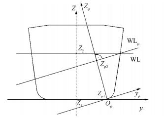
where zφ1 and zφ2 are the integral boundaries for calculation of section area properties of angled waterline, as in Fig. 3, and x1 and x2 are the integral bounds for waterplane area calculations.
|
| Figure 3 Rotated, moving coordinate system |
To avoid non-bijectivity of results and facilitate correct calculations, a suitable orthogonal moving yφ-zφ coordinate system is used, as shown on Fig. 3, rotated for list angle φ, with the origin set to the minimal tangent point Oφ. that changes with list angle φ.
All hydrostatic particulars results can be then described as a function of zφ axis as follows:
| $ \mathit{\boldsymbol{H}}=\mathit{\boldsymbol{H}}\left( {{z}_{\varphi }} \right)=\mathit{\boldsymbol{H}}\left[ z\left( \varphi \right) \right]=\mathit{\boldsymbol{H}}\left( \varphi \right) $ | (11) |
The rotation matrix in the yφ-zφ coordinate system can be written as
| $ \left[ \begin{matrix} {{z}_{\varphi }} \\ {{y}_{\varphi }} \\ \end{matrix} \right]=\text{rot}\left[ \begin{matrix} z \\ y \\ \end{matrix} \right]=\left[ \begin{matrix} \cos \varphi &\sin \varphi \\ -\sin \varphi &\cos \varphi \\ \end{matrix} \right]\left[ \begin{matrix} z \\ y \\ \end{matrix} \right] $ | (12) |
The main characteristic of the above coordinate system is that it is always orthogonal to the observed VL, and its origin corresponds to the minimal z value of the ship's geometry with the general conditions
| $ \frac{\partial f\left( x,z \right)}{\partial x}=0,\ \frac{\partial f\left( x,z \right)}{\partial z}=0 $ | (13) |
By using an interpolation matrix H, yφ can be written as:
| $ {{y}_{\varphi }}=\cos \varphi \cdot H\cdot w-z\cdot \sin \varphi $ | (14) |
According to Ban and Bašić (2015) and Ban (2012), the solutions of integrals (6) to (10) by using PRBFs for the initial coordinate system y – z are
| $ \begin{align} &A=\left. \cos \varphi \left[ \sum\limits_{\begin{smallmatrix} i \\ \beta =3 \end{smallmatrix}}{{{w}_{i}}\left( \frac{{{\left| z-{{z}_{i}} \right|}^{4}}}{4}+{{c}^{3}}z \right)}+\sum\limits_{\begin{smallmatrix} i \\ \beta =1 \end{smallmatrix}}{{{w}_{i}}\left( \frac{{{\left| z-{{z}_{i}} \right|}^{2}}}{2}+c\cdot z \right)} \right] \right|_{{{z}_{1}}}^{{{z}_{2}}}- \\ &\left. \sin \varphi \cdot \frac{{{z}^{2}}}{2} \right|_{{{z}_{1}}}^{{{z}_{2}}} \\ \end{align} $ | (15) |
| $ \begin{align} & {{M}_{y}}=\left. \cos \varphi \left[ \sum\limits_{\begin{matrix} i \\ \beta =3 \\ \end{matrix}}{{{w}_{i}}\frac{{{\left( z-{{z}_{i}} \right)}^{5}}}{5}+\frac{{{\left( z-{{z}_{i}} \right)}^{4}}}{4}{{z}_{i}}+c_{1}^{3}\frac{{{z}^{2}}}{2}} \right] \right|_{{{z}_{1}}}^{{{z}_{2}}}+ \\ & \left. \left. \sum\limits_{\begin{matrix} i \\ \beta =1 \\ \end{matrix}}{\left[ \frac{{{\left( z-{{z}_{i}} \right)}^{3}}}{3}+\frac{{{\left( z-{{z}_{i}} \right)}^{2}}}{2}{{z}_{i}}+{{c}_{2}}\frac{{{z}^{2}}}{2} \right]} \right|_{{{z}_{1}}}^{{{z}_{2}}} \right\}-\left. \sin \varphi \cdot \frac{{{z}^{3}}}{3} \right|_{{{z}_{1}}}^{{{z}_{2}}} \\ \end{align} $ | (16) |
| $ \begin{align} & {{M}_{z}}=\left. \cos \varphi \left[ \sum\limits_{_{\begin{matrix} i \\ \beta =3 \\ \end{matrix}}}{{{w}_{2i}}\left( \frac{{{\left| z-{{z}_{i}} \right|}^{4}}}{4}+{{c}^{3}}z \right)+\sum\limits_{\begin{matrix} i \\ \beta =1 \\ \end{matrix}}{{{w}_{2i}}\left( \frac{{{\left| z-{{z}_{i}} \right|}^{2}}}{2}+c\cdot z \right)}} \right] \right|_{{{z}_{1}}}^{{{z}_{2}}}- \\ & \left. \sin \varphi \cdot \frac{{{z}^{2}}}{2} \right|_{{{z}_{1}}}^{{{z}_{2}}} \\ \end{align} $ | (17) |
| $ \begin{align} &{{I}_{x}}=\left. \cos \varphi \left[ {{\sum }_{\begin{matrix} i \\ \beta =3 \\ \end{matrix}}}{{w}_{3i}}\left( \frac{{{\left| z-{{z}_{i}} \right|}^{4}}}{4}+{{c}^{3}}z \right)+{{\sum }_{\begin{matrix} i \\ \beta =1 \\ \end{matrix}}}{{w}_{3i}}\left( \frac{{{\left| z-{{z}_{i}} \right|}^{2}}}{2}+c\cdot z \right) \right] \right|_{{{z}_{1}}}^{{{z}_{2}}}- \\ &\left. \sin \varphi \cdot \frac{{{z}^{2}}}{2} \right|_{{{z}_{1}}}^{{{z}_{2}}} \\ \end{align} $ | (18) |
| $ \begin{align} &{{I}_{y}}=\left. \sum\limits_{\begin{smallmatrix} i \\ \beta =3 \end{smallmatrix}}{{{w}_{i}}\left[ \frac{{{x}^{6}}}{6}-3\frac{{{x}^{5}}}{5}\left| {{x}_{i}} \right|+3\frac{{{x}^{4}}}{4}{{\left| {{x}_{i}} \right|}^{2}}+\frac{{{x}^{3}}}{3}\left( c_{1}^{3}-{{\left| {{x}_{i}} \right|}^{3}} \right) \right]} \right|_{{{x}_{1}}}^{{{x}_{2}}}- \\ &\left. \sum\limits_{\begin{smallmatrix} i \\ \beta =1 \end{smallmatrix}}{{{w}_{i}}\left[ \frac{{{x}^{4}}}{4}+\frac{{{x}^{3}}}{3}\left( {{c}_{2}}-\left| {{x}_{i}} \right| \right) \right]} \right|_{{{x}_{1}}}^{{{x}_{2}}} \\ \end{align} $ | (19) |
where wi, w2i, and w3i are the weight coefficients obtained for y, y2 and y3, respectively, and ci, c1, and c2 are the shape coefficients of the chosen PRBFs.
Thereafter, complete hydrostatic particulars of ship compartments can be calculated with Boolean geometric algebra by geometrically adding and subtracting areas below the defined curves.
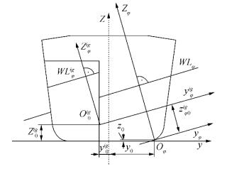
3.3 Relation between ship global and local compartment's coordinate systemsAfter the new globally translated coordinate system yφ–zφ is formed for a change in the ship list angles φ, the relation with the compartments' local coordinate systems yφig-zφig should be established, too, as shown in Fig. 4. Additionally, the origin of coordinate system travels to the minimal ship point depending on rotation angle φ, as shown on Fig. 3. This means that the local coordinate system yφig-zφig of each compartment changes its origin position Oφig, too, depending on the minimal vertical point in the local coordinate system for rotation angle φ.
|
| Figure 4 Relation between global ship's moving coordinate system and local compartment's coordinate system |
Fig. 4 shows that minimal point Oφig of each compartment depends on the ship's list angle φ, where X0≡ {x0, y0, z0} is the global ship minimum for arbitrary ship list angle φ and X0ig≡ {x0ig, y0ig, z0ig} is the minimal point position for an observed compartment Gi.
The components of computational points in the respective compartments can be then calculated for Xφig≡ {xφig, yφig, zφig}, where we are interested in yφig=y0-y0ig and zφig=z0-z0ig.
Now, computational draft value zφ0ig that relates the loading of Gig compartment to the global moving rotated ship coordinate system can be calculated by using the coordinate system rotation matrix from (12) as
| $ z_{\varphi 0}^{ig}=\left( z-{{z}_{0}} \right)\cdot \cos \varphi +\left( y-{{y}_{0}} \right)\cdot \sin \varphi $ | (20) |
Its transverse component according to the rotation transformation matrix (21) is then
| $ y_{\varphi 0}^{ig}=\left( y-{{y}_{0}} \right)\cdot \cos \varphi -\left( z-{{z}_{0}} \right)\cdot \sin \varphi $ | (21) |
The relations (20) and (21) are the basis for correlation of a compartment's hydrostatic particulars values H(0) obtained in the initial coordinate system to the moving rotated coordinate systems H(φ).
3.4 Relation between coordinate systems of initial and open ship hullIt is shown in previous chapters of this paper that affine transformations of geometry can be calculated using PRBF-based descriptions of ship geometry. The associated hydrostatic particulars H0=H(α=0) for the initial ship geometry G0=G(α=0) rotation about the x-axis were calculated, too, for the relevant list angle φ range.
Thus, the initial hydrostatic particulars matrix {H0} ≡ {H00, H01, ..., H0ig, ..., H0NG} can be calculated for all ship compartments Gig as a function of initial geometry general drafts zφ and list angles φ for opening angle α equal to zero. An additional subscript for initial computational draft zφ0 and list angles φ0 can be therefore introduced to designate initial geometry values.
The associated initial set of hydrostatic particulars for any arbitrary compartment without varying ship geometry can be then represented as
| $ \begin{align} &\mathit{\boldsymbol{H}}_{\varphi 0}^{ig}=\mathit{\boldsymbol{H}}_{\varphi }^{ig}\left( {{\varphi }_{0}},\alpha =0 \right)\equiv \{\nabla _{0}^{ig},X_{B0}^{ig},A_{WL0}^{ig},X_{WL0}^{ig},X_{ML0}^{ig},X_{MB0}^{ig}\}, \\ &\ \ \ \ \ \ \ \ \ \ \ \ \ \ \ \ \ \ \ \ \ \ \ \ \ \ \ ig=0,1,...,{{N}_{G}} \\ \end{align} $ | (22) |
where φ0 is initial set of list angles φ = 0, 1, …, max (φ), and α is ship hull opening angle, with ig = 0, …, NH– 1 denoting ship hull outer compartments and ig = NH +1, …, NG denoting inner ship compartments, while NG denotes the total number of ship compartments.
For open hull of the Split TSHD, compartment hydrostatic particulars Hφig depend on additional parameters, namely, ship hull opening angle α and list angle φ as
| $ \mathit{\boldsymbol{H}}=\mathit{\boldsymbol{H}}\left( \varphi ,\alpha \right) $ | (23) |
However, the relationship between the angles in the initial yφ− zφ and open coordinate systems yφ, α− zφ, α is simple and can be written as
| $ \varphi ={{\varphi }_{0}}-\alpha $ | (24) |
The hydrostatic particulars of the open hull Hφig can then be calculated from the initial calculations depending on the split hull open angle a as
| $ \begin{align} &\mathit{\boldsymbol{H}}_{\varphi 0-\alpha }^{ig}=\mathit{\boldsymbol{H}}_{\varphi }^{ig}\left( {{\varphi }_{0}}-\alpha \right)\equiv \{\nabla _{\varphi }^{ig},X_{B\varphi }^{ig},A_{WL\varphi }^{ig},X_{WL\varphi }^{ig},X_{ML\varphi }^{ig},X_{MB\varphi }^{ig}\}, \\ &\ \ \ \ \ \ \ \ \ \ \ \ \ \ \ \ \ \ \ \ \ \ \ \ \ \ \ ig=0,1,...,{{N}_{G}} \\ \end{align} $ | (25) |
To facilitate calculation of hydrostatic particulars Hφig from the initial hydrostatic particulars H0ig, using relation (24), the initial calculated list angles φ0 need to be related to the minimal and the maximal opening angle α values, so that there must exist (sign "∃") φ0 equal to αmax.
Condition 1: Calculated angles φ and initial φ0 list angles need to be related as
| $ \varphi :\exists {{\varphi }_{0}}={{\alpha }_{\min }}\wedge \exists {{\varphi }_{0}}={{\alpha }_{\max }} $ | (26) |
That is, the set of initial list angles φ0 must contain αmin and αmax angles, too, for facilitating the calculation of hydrostatic particulars from the initial list angles, as will be explained further.
The initial hydrostatic particulars of closed ship hull will be calculated in Chapter 5, first, and open Split hull hydrostatic particulars values will be calculated in Chapter 6, where additional relations regarding their position between compartments will be established.
4 Description of Split TSHD ship geometry 4.1 GeneralShips are sailing objects with complex geometries consisting of hydrodynamic outer hull and numerous inner compartments of various shapes. While ship hulls usually have smooth geometries with several possible discontinuities, the inner compartments can consist of flat parts as well as lay on the outer hull, thus taking its form. Then, some ship B, as described in the Ban's PhD thesis (2012), can be defined for its geometry G as set of compartment spaces that consist of outer V and inner U compartments as
| $ \mathit{\boldsymbol{G}}=\mathit{\boldsymbol{V}}+\mathit{\boldsymbol{U}}=\bigcup\limits_{iv}{{{\mathit{\boldsymbol{V}}}_{iv}}}+\bigcup\limits_{iu}{{{\mathit{\boldsymbol{U}}}_{iu}}} $ | (27) |
where outer compartments V ≡ {Viv} represent ship hulls, whose number depend on ship type, with iv = 1, …, NH denoting the ship hull number, while the inner compartments differ in number and shape with U ≡ {Uiu}, iu = 1, …, NU denoting the number of inner compartments in the ship.
More generally, ship geometry can be defined with its all compartments Gig union as
| $ \mathit{\boldsymbol{G}}=\bigcup\limits_{ig}{{{\mathit{\boldsymbol{G}}}_{ig}}} $ | (28) |
where ig = 1, …, NG is the total number of ship compartment geometries such that NG = NH +NU.
Although ship appendices are usually added to ship geometry as a percentage of total displacement volume, they can be described in detail, too, and added to the outer compartments as V ≡ {Viv} + {Aia}, where ia = 1, …, NA is the number of ship appendices.
The inner spaces can be divided further as structural spaces US and non-structural spaces UN depending on whether they lean on the outer ship hull. Therefore, additional structural spaces are determined partly by outer ship hull geometry and they belong to the outer ship geometry subspace as US ⊆ V. After the outer and the inner ship spaces are defined, they can be further represented using some geometry representation method such as the Boundary representation method, as will be shown later in the paper.
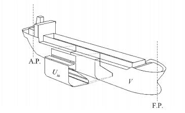
4.2 B-rep description methodWhen explicit RBF methods are used for ship computational geometry description, ship compartments, including boundary elements, vertices, edges and faces related through adjacency, can be created using the surface-based Boundary representation method (B-rep) (Bardis and Patrikalakis, 1994), as shown in Fig. 5 below.
|
| Figure 5 Boundary representation of a ship compartment |
An observed compartment Uiu is then defined by vertex points marked as discontinuity points L, l = 1, …, L in the PRBF description; edge curves C ≡ {Cic}, ic = 1, …, NC defined functionally using PRBFs Cic≡ fic(z), as given in Eq.(29), and face descriptions obtained using surface PRBFs; the foundations of that type of description are given in Ban and Ljubenkov (2015). Usually, edge curves are limited to compartment dimensions, but the composition of PRBFs enables non-two manifold description, that is, curve description can be stretched to the maximal ship height, as will be shown later in the paper.
In practice, the description of a single inner compartment Uiu can be obtained using geometric Boolean algebra on compartment parts P ≡ {Piu, ip}, ip = 1, …, NP defined by the set of curves C ≡ {Ciu, ic} as
| $ {{\mathit{\boldsymbol{U}}}_{iu}}=\bigcup\limits_{ip}{{{\mathit{\boldsymbol{P}}}_{ip}}=\bigcup\limits_{ip}{\bigcup\limits_{ic}{{{\mathit{\boldsymbol{C}}}_{ic}}}}=}\bigcup\limits_{ip}{\bigcup\limits_{ic}{{{f}_{ic}}\left( z \right)}} $ | (29) |
Of course, one of the goals is to reduce part numbers or parts in general with single non-two manifold description of every inner or outer compartment. As will be shown here, it is possible to do so by means of descriptions in which curves are defined with PRBFs, as described in Chapter 2.
4.3 Split TSHD descriptionThe main characteristic of Split TSHDs that makes them different than other ship types is that their geometry G is not constant during unloading, that is, G≠ const.
Therefore, the outer and/or inner compartments change, too, where all inner compartments except the cargo hold retain constant geometry. In the case of the observed Split TSHD in this paper, the ship has three inner compartments on the main frame section: a symmetric cargo hold U1 and two equal non-symmetric ballast tanks U2 and U3 on each side of the ship; U2 and U3 are equal and positioned symmetrically and transversally about the centerline plane. Cargo hold geometry U1 changes during cargo discharge; therefore, U1 ≠ const.
Other inner compartments retain constant geometry, and owing to equality of geometries, only one right ballast tank U2 is observed, and U2 = U3 = const.
Ship geometry can therefore be divided into constant and variable compartments as, will be described further. However, the ship must first be described with its initial geometry by using the B-rep method.
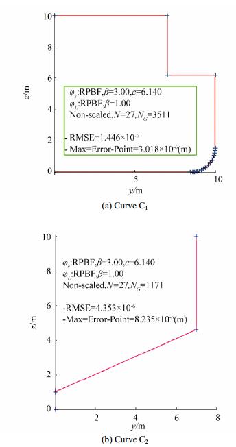
4.3.1 Initial geometry descriptionBy using the B-rep method, we describe the ship by using its cross section on the main frame, thus showing its typical transverse compartment arrangement, as in Fig. 1. The figure shows that the inner compartment arrangement in the cargo space of Split TSHD consists of cargo hold and ballast tanks, with a raised bulwark rail. The ship's cross section can be then described using two curves C1 and C2 only, with two PRBF descriptions f1(z) and f2(z). These two curves represent non-two manifold description, stretching from the ship's baseline to highest point in the ship's cargo space, with input points given in Table A1, Appendix A.
Therefore, transverse ship geometry can be described using two complex curves: outer hull curve C1 and inner cargo hold curve C2 composed of cubic and linear PRBFs, as shown in Fig. 6, where section symmetry is used to describe only one side of the section.
|
| Figure 6 Description Split TSHD main frame section curves C1 and C2 using PRBF |
Fig. 6 shows the results of hull section curve description for the outer hull section by using PRBFs with β = {3, 1}. After the section curves are determined, ship cross section can be described using the B-rep method, as in Fig. 7.
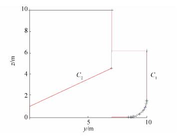
|
| Figure 7 B-rep description of Split TSHD main frame section using PRBF |
To accurately describe the inner compartments, edge curves must be closed, that is, curves C1 and C2 must intersect. Thus, the ballast tank can be obtained, too, from the intersecting curves C1 and C2, together with the outer hull and the inner cargo hold.
It can be seen from Fig. 7 that the outer hull compartment V can be obtained from curve C1 using its transversal symmetry, while the cargo hold can be obtained similarly using curve C2.
The ballast tank can be obtained by subtraction of areas under curves C1 and C2, thus describing the entire ship's cross section.
4.3.2 Variable ship geometryIn the general case, change of ship geometry G for affine geometry transformations can be described a robotics analogy, using geometric translations T ≡ {a, b, c} and the associated geometric rotations R ≡ {α, β, γ} as
| $ \mathrm{G}=\mathrm{G}\left( T,R \right) $ | (30) |
and influence on ship hydrostatic particulars as
| $ \mathit{\boldsymbol{H}}=\mathit{\boldsymbol{H}}\left( T,R \right) $ | (31) |
In the case of Split TSHD, the change in geometry is obtained by rotation around joint point Ω only, as shown on Fig. 1. This means that changes in the geometry and the hydrostatic particulars of the Split TSHD in Eqs. (30) and (31) depend on rotation about x axis only, and, therefore, the above expressions change to
| $ \mathit{\boldsymbol{G}}=\mathit{\boldsymbol{G}}\left( \alpha \right) $ | (32) |
and
| $ \mathit{\boldsymbol{H}}=\mathit{\boldsymbol{H}}\left( \alpha \right) $ | (33) |
Fig. 1 shows the Split TSHD in its unloading phase, where the ship's hull splits in two by rotation around joint Ω≡ {YΩ, ZΩ} positioned at a certain height along the ship's centreline, to discharge bulk cargo using mass flow. Then, rotation α of the hull parts around joint Ω can be generally expressed in terms of y and z as
| $ \begin{align} &{{z}_{\alpha }}={{\mathit{\boldsymbol{Z}}}_{\mathit{\Omega }}}-\left( z\cdot \cos \alpha +y\cdot \cos \alpha \right) \\ &{{y}_{\alpha }}={{\mathit{\boldsymbol{Y}}}_{\mathit{\Omega }}}-\left( y\cdot \cos \alpha +z\cdot \cos \alpha \right) \\ \end{align} $ | (34) |
Because ship curves C are described using functions, C ≡ y = f(z), the corresponding hull rotation can be expressed for curve C as
| $ \begin{align} &{{z}_{\alpha }}={{\mathit{\boldsymbol{Z}}}_{\mathit{\Omega }}}-\left( z\cdot \cos \alpha +f\left( z \right)\cdot \cos \alpha \right) \\ &{{y}_{\alpha }}={{\mathit{\boldsymbol{Y}}}_{\mathit{\Omega }}}-\left( f\left( z \right)\cdot \cos \alpha -z\cdot \cos \alpha \right) \\ \end{align} $ | (35) |
In the case of the test ship in this paper, the joint is set at point Ω ≡ {0, 10}.
5 Calculation of compartments' hydrostatic particulars for initial geometry 5.1 Outer hull calculationOuter hull geometry of the observed ship, in the initial condition without opening, consists of a flat bottom and sides with rounded bilges, with two deck discontinuities, as shown in Fig. 7 and described in Appendix A. To describe this outer geometry globally, it necessary to use non-two manifold methods such as description using a composition of cubic and linear PRBFs, as described before.
The associated hydrostatic results for the entire outer hull are shown on the right side of the outer hull section using PRBFs with β = {3, 1}, as shown in Fig. 8.

|
| Figure 8 Right side outer hull hydrostatic particulars for list angle φ= 0° |
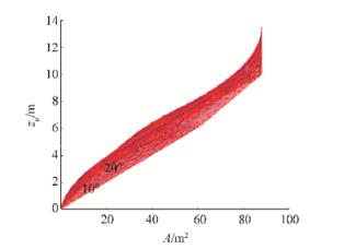
Regarding the precision of PRBF integration, the maximal calculated outer hull section area at one side is A = 88.154 1 m2 and the center of buoyancy zB = 4.628 3 m equals the theoretical value for that observed frame section of Split TSHD test ship, as described on Fig. A1 and in Appendix A.
Except the calculation for even keel, hydrostatic particulars for angled ship can be calculated, too, according to the direct analytical solutions of basic hydrostatic integrals, as given in Ban (2012). Since maximal opening angle αmax=13°, hydrostatic particulars calculations are made for list angle φ0 = 0° – 89°, with △φ0 = 1° step, thus satisfying condition (26).
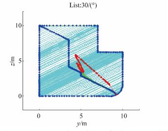
An example of hydrostatic particulars for the right side of outer geometry V1 calculations for list angle φ0 = 30° is shown in Fig. 9.
|
| Figure 9 Outer hull hydrostatic particulars for list angle φ0=30° |
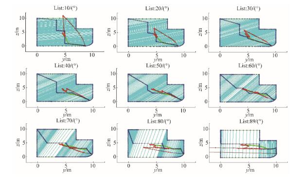
The calculation results for list angle range φ0 are presented in Appendix B, in Fig. B2 for section areas and Biles representation with step △φ0 = 10° in Fig. B3.
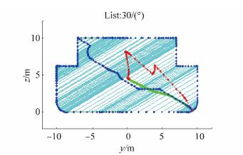
(Note: Throughout this paper, Biles-like representations of hydrostatic calculations have centers of buoyancy XB marked with green color, centers of waterline XWL with blue, and centers of transverse metacenters XMB marked red.)
5.2 Inner hull calculationsThe calculations of inner hull compartments depend on whether they are symmetric or not. If they are symmetric, the hydrostatic particulars calculations do not change for negative list angles. If they are non-symmetric, separate calculations should be performed positive and negative list angles.
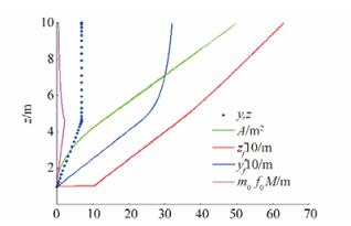
5.2.1 Cargo holdThe Cargo hold of the test ship is an open and symmetric compartment, and can be therefore described by its right side only, as in Fig. 10, which shows cargo hold hydrostatic particulars.
|
| Figure 10 Right side cargo hold hydrostatic particulars for list angle φ0= 0° |
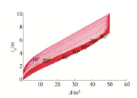
After hydrostatic particulars are calculated for cargo hold and theoretical even keel, the maximal cross section value is obtained as A = 50.399 3 m2 and center of buoyancy as zB = 6.325 1 m compared to the actual values of 50.4 m2 and 6.325 m. Their values are then calculated for list angle range φ0 = 0°–89°, with △φ0 = 1° step, similar as for the ship's hull in the previous subchapter. Although the Split TSHD has an open cargo hold, the observed frame section curve will be closed, and the results of those calculations for cargo hold are presented with step △φ0 = 10°, as shown in Appendix B, Fig. B5. The associated section areas are shown in Fig. B4 and in Appendix B.
The hydrostatic particulars of cargo hold U1 geometry calculations are shown in Fig. 11 for list angles φ0 = 30° and φ0 = −30° by using Biles-like representation.

|
| Figure 11 Cargo hold hydrostatic particulars for list angles |
The observed ballast tank is non-symmetric. Its basic hydrostatic particulars are calculated for even keel, i.e., φ0 = 0°, as shown in Fig. 12.

|
| Figure 12 Right-side ballast tank hydrostatic particulars for list angle φ0= 0° |
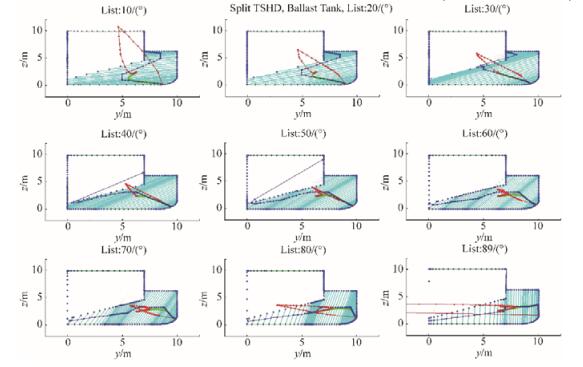
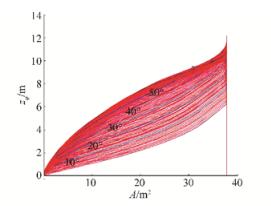
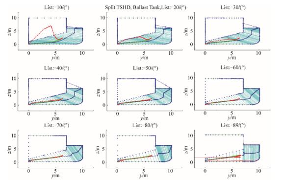
The hydrostatic particulars of the non-symmetric ballast tank need to be calculated for positive list angles φ = 0°–89°, with step △φ = 1° and negative list angles φ = 0°–89°, with negative △φ = −1° step. The calculation results are presented in Appendix B using Biles representation, with step △φ = ±1°, as shows in Figs. B5 and B7, while the results shown here are for list angles φ = 30° and φ = −30°. The associated section areas are shown in Fig. B4 for positive list angles and in Fig. B6 for negative list angles; the same results are also give in Appendix B.
The maximal calculated values are A=37.715 6 m2 and center of buoyancy zB= 2.3573 m compared to the actual corresponding values of 37.715 9 m2 and 2.357 3 m, respectively.
Fig. 13 below shows the hydrostatic particulars of ballast tank U2 for list angles φ = 30° and φ = −30°, while the overall initial list angles results are shown in Appendix B.

|
| Figure 13 Ballast tank hydrostatic particulars for list angles |
After all hydrostatic particulars of the outer hull and the inner compartments are preprocessed, total hydrostatic particulars of the ship can be calculated for initial ship geometry without opening of the hull. Moreover, those calculations are the basis for further variable geometry calculations, where no additional hydrostatic integrals need to be calculated. In order to connect the data of various compartments, their coordinate systems should be related.
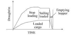
6 Calculation properties of Split TSHD cargo discharge for symmetric opening 6.1 Cargo discharge procedureAs mentioned before, Split TSHD is special type of ship that opens her cargo hold, called hopper, to discharge bulk cargo using gravitational flow. The typical loading/unloading curve on Fig. 14 shows that the unloading procedure of in emptying the hopper is fast, with cargo discharge occurring at free fall speed after exiting the hopper (Miadema, 2008). That process of unloading bulk cargo using mass flow in variable hold geometry through three types of fluid zones—air, air-water mixture and water—is very complex and it will be investigated separately using CFD methods. The hydrostatic calculations made in this paper will be therefore the basis for those calculations, as will be shown in subsequent papers by the authors of this paper. During cargo discharge, hull splitting is done by the complex ship hydraulic system with a procedure that can last for several tens of seconds to few minutes; the corresponding unloading curve is shown in Fig. 14. Therefore, the unloading procedure is performed within a short time span, and it is necessary to observe intermediate unloading positions or ship geometry variations.
|
| Figure 14 Typical loading/unloading curve |
Although the change in ship geometry is continuous, it is not observed as such because hydrostatic calculations are performed for some list angle step △φ = ±1. Therefore, changes in the ship's geometry will be observed with split angle increment △α = 1 to final hull opening split angle α, which is here defined as αmax = ±13°.
Therefore, the analysis will continue with investigation of hydrostatic characteristics of cargo unloading using Split TSHD. The final part of the loading/unloading curve in Fig. 14 shows unloading through a silo-like hopper cargo hold that has variable geometry in order to empty it completely. Regarding the ship unloading procedure, it can be divided into four phases based on loading conditions and ship geometry:
1) Closed ship, loaded with bulk cargo mixture—initial ship geometry,
2) Ship with open hull, cargo-water mixture in hopper—variable ship geometry,
3) Ship with open hull, empty hopper—variable ship geometry,
4) Closed ship, empty hopper—initial ship geometry.
The calculation of hydrostatic particulars for unloading conditions in phases 1) and 4) represent standard calculations for initial ship geometry that have been performed in practice, with addition of calculation for range of list angles instead of even keel only.
On the other hand, Split TSHD ship geometry is not constant in phases 2) and 3) of the cargo unloading procedure. Moreover, cargo is discharged through the hopper in phase 2), and therefore, not only the outer but also the inner geometry changes in this unloading phase. In this paper, the focus is on loading situations with variable geometry, and the corresponding hydrostatic particulars calculation procedure based on initial geometry calculations is shown in this chapter, using procedures that will be described further.
6.2 Geometric characteristics of split ship hull openingSplit TSHD are special ships whose hull splits in two to discharge bulk cargo using mass flow, as mentioned before. Therefore, in ship unloading, cargo discharge is done using mass flow of bulk cargo by hull opening, thus creating the silo effect, as shown in Fig. 15.

|
| Figure 15 Mass flow effect of bulk cargo in silo-shaped hopper hold of Split TSHD |
During the various phases of the hull opening process, ship geometry is not constant and it changes from initial {G} to variable geometries depending on opening angle α, as described in Eq. (6). Regarding the unloading process, geometric details of the phases with variable geometry are as follows:
● Phase 2):
During cargo discharge, the ship is still mono-hull, that is, pressure pc from the discharged pressure is higher than the hydrostatic pressure ph, and therefore, no water enters the ship. The ship changes its geometry but retains the same number of compartments ig = const.
● Phase 3):
The compartments that are changed are outer compartment, that is, ship's hull V, and cargo hold U1, as described before. After cargo is unloaded from the ship, the initial mono-hull ship becomes a twin-hull ship with two ship sides and two hulls V0 and V1, and the compartment numbering changes from ig = 1 to Nig to ig = 0 to Nig.
In phase 2), mass flow of cargo-water mixture occurs, with simultaneous change of cargo hold filling and ship draft d, which is a hydrodynamic problem in nature and cannot be solved using only hydrostatic forces. Anyway, hydrostatic particulars are basics for those calculations, and they will be calculated for the open hopper, as described in this chapter.
In contrast to phase 2), the other phases are based on hydrostatic calculations only and can be calculated completely quasi-statically, as will be shown further.
Thereafter, it is necessary to set relations between the initial and the variable geometry for calculating list angles φ0 and hull split angles α, together with relations for calculation of draft zφ for different list angles φ for ship with open hull.
6.3 Calculation of computational angles for hull openingAlthough the Split TSHD has variable geometry, stability regulations regarding approval of its loading conditions do not cover intermediate ship loading conditions, but initial and final unloading conditions only. Therefore, geometry changes are not calculated, neither are the hydrostatic particulars in the split hull condition. It will be shown in this chapter that the necessary hydrostatic calculations can be performed using PRBF B-rep description of the initial ship geometry.
After the initial ship hydrostatic particulars H0 are calculated, as shown in Chapter 5, the split ship hydrostatic particulars H for open hull can be calculated too for arbitrary symmetric ship hull split angles α, as shown in Fig. 1. During splitting, the hull opens by rotating about joint point Ω with some speed, therefore rotating from the initial zero angle to the maximal opening angle αmax. Then, the set of calculation opening angles α, similar to calculation rotation angles φ, can be defined as
| $ a=\left[ 0,{{\alpha }_{\max }} \right],\Delta \alpha =1° $ | (36) |
To enable connection between geometries and hydrostatic calculations, list angles φ for the open hull need to satisfy Condition 1, as in Eq. (26). Moreover, since the ship hull opens about joint Ω, symmetry need to be employed in geometry description, as shown in Chapter 5. Therefore, in the case of geometry description using symmetry, the following new condition applies.
Condition 2: In the case of geometric calculations using symmetry, the set of initial calculation list angles φ0 must have positive and negative angles for description of split hull geometry with
| $ {{\varphi }_{0}}=\left[ -{{\varphi }_{\max }},{{\varphi }_{\max }} \right] $ | (37) |
Thereafter, using Eq. (24) calculation list angles for hull opening can be determined as
| $ \varphi =\left[ -{{\varphi }_{\max }},{{\varphi }_{\max }} \right]\pm \alpha ,\ \ \Delta \varphi =1° $ | (38) |
To satisfy both Conditions 1 and 2, calculation list angles for hull opening can be determined for αmax and
| $ \varphi =\left[ -{{\varphi }_{\max }},{{\varphi }_{\max }} \right]\pm {{\alpha }_{\max }},\ \ \Delta \varphi =1° $ | (39) |
i.e., for chosen angles αmax = ±13° and φmax = ±89°, we have
| $ \varphi =\left[ -89°,89° \right]\pm 13°,\ \ \Delta \varphi =1° $ | (40) |
After summing, the final calculation angles φ for the ship in split conditions can be calculated as
| $ \varphi =\left[ -76°,76° \right],\ \ \Delta \varphi =1° $ | (41) |
as will be shown in subsequent figures.
Therefore, the split angle α is covered with those calculations, and no new hydrostatic particulars calculations are required for ship hull splitting.
Owing to symmetry, the calculations are divided on the positive and the negative sides, so list angle values are divided into positive and negative ones. It can be concluded from Eq. (24) that for the lower side of the ship, where lies the minimum point Oig of the translated rotating coordinate system yφ–zφ, new list angles φ for split ship should be calculated as φ=φ0–α. On the opposite side of the centerline, ship compartments can be observed as having negative φ values, and therefore, the associated calculation list angles φ are φ = −φ0−α = −(φ0+α). That is, we have calculation angles φ defined for initial list angles φ0 and open hull angle α as
| $ \begin{align} & \text{If}\ \varphi \ge 0:\varphi ={{\varphi }_{0}}-\alpha \\ & \text{If}\ \varphi <0:\varphi =-\left( {{\varphi }_{0}}-\alpha \right) \\ \end{align} $ | (42) |
Eq. (42) can be rewritten depending on the position of compartment Gig relative to the centerline as
| $ {{\varphi }_{ig}}=\text{sign}\left( {{y}_{Oig}} \right)\cdot {{\varphi }_{0}}-a,\ \ \ \ ig=0,1,...,{{N}_{G}} $ | (43) |
where yOig is the transverse coordinate of the minimal point for an observed compartment Gig.
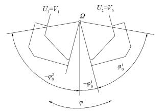
In the case of open hull for the Split TSHD, described using the symmetric PRBF B-rep method, calculation angles φ are determined according to the position of the observed inner compartments U1 and U2, which are buoyancy compartments, as shown in Fig. 16.
|
| Figure 16 Calculation zones for global calculation angles φ |
It can be seen from the above figure that the hydrostatic particulars of the right ballast tank compartments U2 need to be determined for positive and negative initial calculation angles φ0 in order to cover all open hull angles φ. By contrast, the left compartments can be calculated for negative initial calculation angles φ0 only. However, in the observed example of split pontoon, the right and the left compartments are symmetric, and therefore, single U2 compartment calculations of their hydrostatic particulars H2 are performed for positive and negative initial calculation angles φ0, as shown in 5.2.2, where the hydrostatic particulars of ballast tank U1 are calculated.
6.4 Total ship hydrostatic particulars calculationsAfter the coordinate systems of all ship compartments Gig are connected using Eqs. (20), and (21) and (24) the relationship between the initial computational angles and the maximal opening angles is established in Eqs. (38)–(41), the total ship hydrostatic particulars for split hull can be calculated now, as will be shown in this subchapter.
Because of the symmetry employed, the calculated hydrostatic particulars here will be divided into right ones with HR for positive computational angles φ > 0 and left ones designated with HL calculated for negative computational angles φ < 0. Thereafter, it is necessary to determine the calculation zones for the ship's right and left side hydrostatic particulars as a function of the global calculation draft zφ, as shown in Fig. 17.

|
| Figure 17 Calculation zones for global calculation draft zφ |
The calculation zones shown in Fig. 17 depend on the positions of the inner compartments Uiu related to the global coordinate system yφ–zφ through relations determined before in Eq. (12). In the case of the open hull ship situation without cargo, as in Fig. 17, the inner tanks become buoyancy compartments, that is, outer tanks V. They are then determined depending on the minimal compartment Gig points, that is, origins Oφig≡ Omin of the local compartment's coordinate systems yφig-zφig and their relationship with the global moving rotated coordinate system with its origin at Oφ, as defined in Eqs. (20) and (21).
It can be seen from Fig. 17 that the overall minimal calculation point and the origin of the moving rotated coordinate system do not coincide with the minimal right geometry side point TDmin, but should be determined as the minimal right side point min (zφ1). Additional significant points for calculation zone determination are the minimal left side point TLmin that coincides with the point min (zφ2) and the maximal points on both sides of observed geometry, namely, TLmax ≡ min (zφ2) and TDmax ≡ min (zφ1).
The zones for the above example shown in Fig. 17 are
| $ \begin{align} &\text{Ⅰ}:\ \ \min \left( z_{\varphi }^{1} \right)\le {{z}_{\varphi }}=z_{\varphi }^{1}\le z_{\varphi 0}^{2} \\ &\text{Ⅱ}:\ \ \min \left( z_{\varphi }^{2} \right)<{{z}_{\varphi }}\le \max \left( z_{\varphi 0}^{1} \right) \\ &\text{Ⅲ}:\ \ \min \left( z_{\varphi }^{1} \right)< {{z}_{\varphi }}\le \max \left( z_{\varphi 0}^{2} \right) \\ \end{align} $ | (44) |
Depending on the calculation zone characteristics, total hydrostatic particulars H are then calculated for the observed global draft zφ by summing the corresponding compartments' hydrostatic particulars Hϕig in the zone of their influence.
The calculation hydrostatic particulars are then basic values that are not known, with values such as frame area A, static area moment MB, waterplane length dWL, waterplane area moment MWL, and moment of inertia or second area moment IB. The associated hydrostatic particulars for the
| $ \begin{align} &\mathit{\boldsymbol{H}}_{\varphi }^{ig}=\{{{A}^{ig}},M_{B,y}^{ig},M_{B,z}^{ig},{{d}_{WL}},M_{WL,y}^{ig},M_{WL,z}^{ig},I_{B}^{ig},I_{L}^{ig}\} \\ &\ \ \ \ \ \ \ \ \ \ \ \ \ \ \ \ ig=0,1,...,{{N}_{G}} \\ \end{align} $ | (45) |
So, for the case shown in Fig. 17, for single compartments, the values of hydrostatic particulars are taken for the ruling compartment, while for overlapping compartments, they can be calculated by summing the basic values in Eq. (45) using Boolean algebra. Therefore, depending on the calculation zone, the hydrostatic particulars are
| $ \begin{align} & \rm{Ⅰ}:\ \ {{\mathit{\boldsymbol{H}}}_{\varphi }}\rm{=}\mathit{\boldsymbol{H}}_{\varphi }^{1} \\ & \rm{Ⅱ}:\ \ {{\mathit{\boldsymbol{H}}}_{\varphi }}\rm{=}\mathit{\boldsymbol{H}}_{\varphi }^{1}+\mathit{\boldsymbol{H}}_{\varphi }^{2} \\ & \rm{Ⅲ}:\ \ {{\mathit{\boldsymbol{H}}}_{\varphi }}\rm{=}\mathit{\boldsymbol{H}}_{\varphi }^{2} \\ \end{align} $ | (46) |
i.e., the values of section area A, static area moments {MB, y, MB, z}, waterplane area moments {MWL, y, MWL, z}, and moments of inertia or second area moments {IL, IB} for compartments with overlapping calculating drafts zφ have to be summed; thereafter, the distribution of total hydrostatic particulars Hφ over the entire calculation draft zφ axis and for all list angles φ can be determined. For the overlapping zone, therefore, it is
| $ \begin{align} & \rm{Ⅱ}: \\ & {{\mathit{\boldsymbol{H}}}_{\varphi }}\left( {{z}_{\varphi }} \right)=\left\{ \sum\limits_{ig}{{{A}^{ig}}\left( {{z}_{\varphi }} \right),\sum\limits_{ig}{M_{B,y}^{ig}\left( {{z}_{\varphi }} \right),\sum\limits_{ig}{M_{B,z}^{ig}\left( {{z}_{\varphi }} \right)},}} \right. \\ & \left. \sum\limits_{ig}{d_{WL,z}^{ig}\left( {{z}_{\varphi }} \right),\sum\limits_{ig}{M_{WL,y}^{ig}\left( {{z}_{\varphi }} \right),\sum\limits_{ig}{M_{WL,z}^{ig}\left( {{z}_{\varphi }} \right)},\sum\limits_{ig}{I_{B}^{ig}\left( {{z}_{\varphi }} \right),\sum\limits_{ig}{I_{L}^{ig}\left( {{z}_{\varphi }} \right)}}}} \right\} \\ \end{align} $ | (47) |
Moreover, that is not the case only for ships with split hull, but for all ships, where their geometrical and hydrostatic properties depend on some rotation angle φ and relative compartment position, as previously described in Eq. (20) and Eq. (21).
After that, it is necessary to sum all hydrostatic particular values using Boolean geometric algebra, and ship topological properties, as will be shown further.
The respective pseudo-code definitions of hydrostatic properties calculation for open Split TSHD ship during discharge is given below:
'TITLE: OPEN SPLIT TSHD SHIP CALCULATION PROCEDURE FOR DRAFTS AND LIST ANGLES
'NOTE: All calculations are performed for right frame section side.
' This means that the lowest right opening point PR is always lower than the lowest left opening point PL
INPUT:
Initial geometry properties for initial list angles:
G (1), G (2), H (1), H (2)
Opening angles:
'right angleR (always positive)
'left angleL (always negative)
Drafts:
'Geometry compartments rotation around joint Ω, for opening angles angleR and angleL
'Calculating drafts in moved and rotated coordinate system
CD
' Calculating drafts in moved and rotated coordinate system for geometry parts
CD0(1), CD0(2)
'Calculating drafts determination
' 1. From minimal point Omin, on right section side, to maximal point on left section side
' 2. Calculation sections determination according to minimal and maximal geometry points
Lower opening points
PR (YR, ZR), PL (YL, ZL)
Angles definition
'Calculation angles for initial geometry calculations
list_angleR0 = 0 to 89; list_angleL0 = 0 to-89;
'Calculation angles for geometry parts depending on sides: right, left
right_angle = list_angleR0 – angleR; right_angle > =0
left_angle = abs (list_angleL0 – angleL);
List of calculation angles (always positive)
max (left_angle) = max (abs (list_angleL0 – angleL));
list_angle = any (right_angle – angleR = abs (left_angle + angleL));
Crit angle
' List angle where right frame section side becomes lower than left side:
Crit angle = atan ((ZR – ZL)/(ZR – YL))
CALCULATION:
function OpenShip_HydrostaticsCalculation
{
for i = 1:size (list_angle)
for j = 1:size (CD)
'Determination of calculation side
if list_angle (i) < =crit_angle And CD (j) < =min (CD0(2))
' Left side lower – left side is main calculation side
' Sign Correction: Sign =-Sign;
G (i, j)= Sign · G (2);
H (i, j)= Sign · H (2);
elseif CD (j) < =max (CD0(1))
' Right side lower – right side is main calculation side
' No sign correction
G1= G (1);
H1= H (1);
G2=interpolation (G (2), CD0(2))
H2=interpolation (H (2), CD0(2))
' Both sides summation
G (i, j) = G1±G2
H (i, j) = H1±H2
else ' CD (j) > max (CD0(1))
G (i, j)= G (2);
H (i, j)= H (2);
end
end
end
OUTPUT:
G, H
}
7 Calculation resultsThe Split TSHD ship has four unloading phases that are defined in previous chapter. The first and the last phases correspond to closed ship with initial geometry that is solved and described in calculations for outer ship compartment, in Chapter 5.1 and Appendices C and D. Their hydrostatic particulars can be then calculated from the initial values using symmetry and the predefined initial hydrostatic particulars results, as will be described in Chapter 7.1. Moreover, after the hydrostatic particulars are precalculated for initial ship geometry described using analytical the PRBF B-rep method, intermediate ship unloading conditions, determined as phases 2) and 3) in the ship's discharge procedure, can be determined according to the procedure described in this paper.
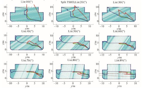
7.1 Cargo discharge unloading phases with initial, constant geometryDischarge unloading phases 1) and 4) are calculated for closed hopper of Split TSHD, and therefore have hydrostatic particulars of initial ship geometry. Their results are shown on Figs. 18 to 20, and Fig. B1 in Appendix B, where Biles like representation of hydrostatic particulars results are shown for list angles φ0 = 0° to 89°, with step △φ0 = 10°.
|
| Figure 18 Biles representation of Split TSHD closed hull in phases 1) and 4), for list angleφ0= 30° |
|
| Figure 19 Section Areas for Split TSHDclosed hullfor list angle range φ= 0° to 89°, step △φ= 1° |
|
| Figure 20 Split TSHD closed hull pantocarene isoclines for calculation list angles φ=[0°, φmax=89°] during discharge phases 1) and 4) |
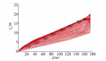
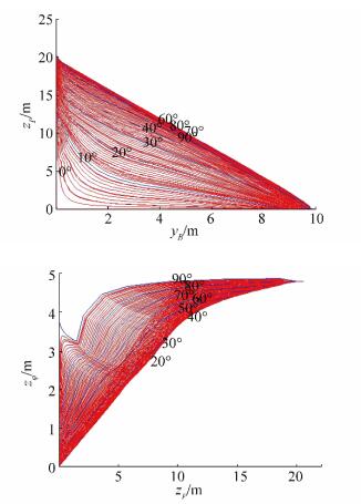
Fig. 19 shows section areas A for whole range of list angles φ from 0° to 89° with step △φ = 1°, determined for calculating drafts zP, while Fig. 20 shows corresponding two-parametric pantocarene isoclines for closed Split TSHD. The maximal section area obtained after calculation is A = 176.308 2 m2, with vertical center of buoyancy zB=4.628 3 m, that corresponds to double values on one side of the ship.
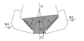
7.2 Cargo discharge unloading phase for open cargo hold of Split TSHDUnloading ship condition using cargo discharge through silo shaped open hull is very complex physical problem that has to be solved using computational fluid dynamics simulation based calculations. Moreover, the cargo types in ship dredgers are various types of bulk cargo like silt, sand, gravel and so on, usually mixed with water, thus forming mixture of unknown density and viscosity. Fig. 15 in Chapter 6.2 explains that mass flow using gravitational force creates larger cargo weight pressure pw than hydrostatic pressure on ship's opening at bottom, ph, with pw > ph.
The Fig. 21 additionally describes relations between pressures, and outer ship and inner compartment waterlines. It is also shown that ship's position on water therefore depends on cargo weight pressure pw distribution on cargo hold inner walls, which is lowering during cargo discharging and hopper opening.
|
| Figure 21 Split hull unloading cargo discharge phase |
Regarding ship geometric characteristics in this unloading phase, it is visible from the figure that cargo hold splits in two symmetric compartments U1, with additional cargo space △G that is formed during hopper opening. Therefore, hydrostatic calculations for open ship hull have additional volume displacement to be added to ship buoyancy force B.
Except additional volume obtained by ship outer hull opening, it is necessary to calculate the additional amount of water that enters ship when her side reaches water level, too. In the case of closed ship this will be water on deck that produces hydrostatic pressure there, while for opened ship without deck it is flooded water. For split TSHD, it is additional water that enters ship for larger list angles that should be included in hydrostatic calculations with volume UD as shown on Fig. 22.

|
| Figure 22 Additional volume for hull side entering water situation |
The calculation of belonging overall geometric and hydrostatic particulars can be done using similar equation to Eq. (47) with calculation parts changing to ig = iv + id, where id is the number of additional ship volumes. For open ship id equals two, corresponding to additional cargo space △G and additional entering water volume UD. Water plane characteristics, on the other hand cannot be calculated by addition, but by forming joint volume space as shown in Eq. (48) below. Since all displacement volumes depend on opening angle α we have:
| $ \begin{align} & {{\mathit{\boldsymbol{H}}}_{\varphi ,\alpha }}=\left[ z\left( \varphi ,\alpha \right) \right]\equiv \\ & \left\{ \sum\limits_{ig}{{{A}^{ig}},\sum\limits_{ig}{M_{B,y}^{ig},\sum\limits_{ig}{M_{B,z}^{ig},}}}{{d}_{VL}},{{M}_{VL,z}},{{M}_{VL,y}},{{I}_{L}},{{I}_{B}} \right\} \\ \end{align} $ | (48) |
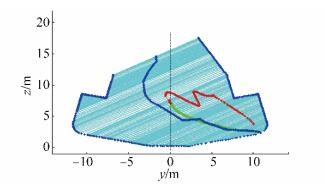
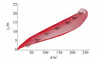
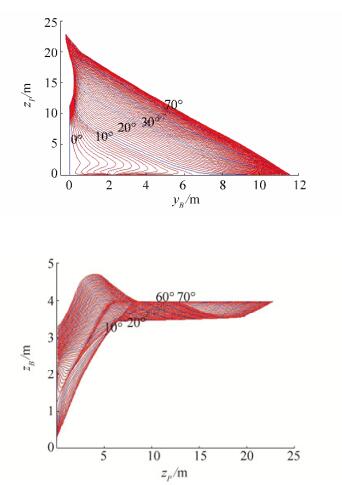
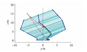
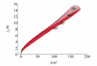
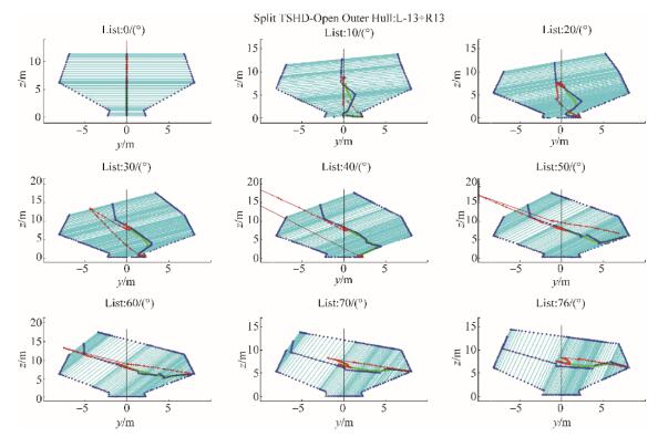
The example of the results of the calculation for ship in phase 2) of unloading cargo procedure are shown on Figs. 23 to 26, where ship hydrostatic particulars are calculated for opening hull angle α = 13°. Beside outer hull hydrostatic particulars calculation, cargo hold hydrostatic particulars are calculated too, with results shown on Figs. 27 to 30.
|
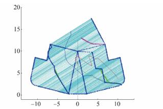
| Figure 23 Calculation parts for open outer hull hydrostatic particulars determination for list angle φ = 30° |
|
| Figure 24 Split TSHD open outer hull hydrostatic particulars for list angle φ = 30° during discharge phase 2) |
|
| Figure 25 Split TSHD open outer hull section area values for calculation list angles φ = [0°, φmax = 76°] during discharge phase 2) |
|
| Figure 26 Split TSHD open outer hull pantocarene isoclines for calculation list angles j = [0°, φmax =76°] during discharge phase 2) |

|
| Figure 27 Calculation parts for open cargo hold hydrostatic particulars determination for list angleφ = 30° |
|
| Figure 28 Open cargo hold hydrostatic particulars for list angle φ = 30° during discharge phase 2) |
|
| Figure 29 Open cargo hold section area values for list angles φ = [0°, φmax = 76°] during discharge phase 2) |

|
| Figure 30 Open cargo hold two-parametric pantocarene isoclines for calculation list angles [0°, φmax = 76°] during discharge phase 2) |
Overall calculation thereby contain repeating of above calculations for some range of split angles α = [0 αmax] with step △α = 1°, thus covering all necessary hydrostatics calculations.
7.2.1 Outer hull hydrostatic particulars for discharge phase 2The volume of additional cargo space △G can be easily calculated since it has regular shape of trapezoid in general, while additional entering water volume UD has variable geometry depending on list angle. All parts are than summed and single volume obtained, as shown on Figs. 23, 24 and Fig. C1 in Appendix C, with areas and pantocarene isocline curves shown on Figs. 25 and 26.
7.2.2 Cargo hold hydrostatic particulars for discharge phase 2In this way, necessary hydrostatic particulars for whole range of opening angles α can be calculated for outer hull after opening and inner cargo hold, thus enabling cargo mass flow discharge calculation for ship with split hull that will be topics of further investigation. As a result, belonging opening angles data files will be created containing all necessary hydrostatic {H} and geometric results{G}.
7.3 Discharged cargo loading condition with open Split TSHD shipAfter cargo is unloaded from ship in phase 2) of unloading procedure, phase 3) occurs with ship having empty cargo hold. Since no cargo pressures water on the bottom of the ship, it enters ship's hopper and she becomes twin-hull ship, instead of mono-hull, as described before. Ship's buoyancy compartments are now ballast tanks U2 and U3, while cargo hold U1 has no role in ship's floating.
Hydrostatic particulars for discharge phase 3) are then calculated using Eq. (47) modified for Boolean subtraction of parts, when ballast tank spaces are obtained from initial curves
| $ \begin{align} &{{\mathit{\boldsymbol{H}}}_{\varphi }}=\left[ z\left( \phi ,\alpha \right) \right]\equiv \\ &\left\{ \sum\limits_{ig}{\pm {{A}^{ig}},\sum\limits_{ig}{\pm M_{B,y}^{ig},\sum\limits_{ig}{\pm M_{B,z}^{ig},}}}\sum\limits_{ig}{\pm I_{L}^{ig},}\sum\limits_{ig}{\pm I_{B}^{ig}} \right\} \\ \end{align} $ | (49) |
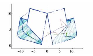
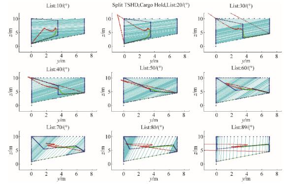
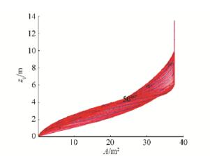
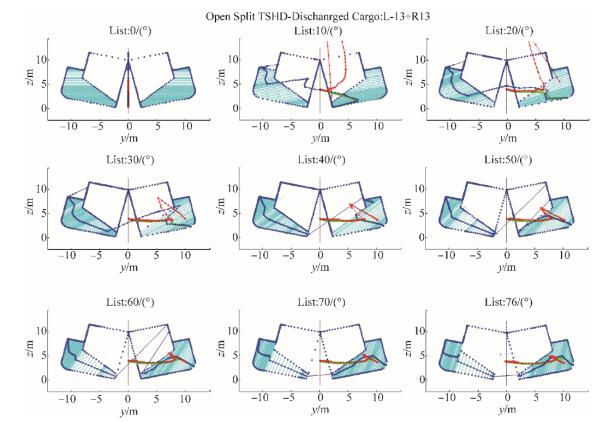
As shown for cargo hold, the example of the results of the calculation for ship in phase 3) of ship unloading, are shown on Figs. 31 to 33 and Fig. D1 in Appendix D, where ship hydrostatic particulars are calculated for opening hull angle α =13°, according to Eq. (47). Overall calculation here also contain repeating of above calculations for some range of split angles α = [0, αmax] with step △α = 1°, thus covering all necessary hydrostatics calculations. Maximal ship cross section area calculated is then A = 75.431 2 m2, just near twice of initial ballast cross section area on one side of the ship.
|
| Figure 31 Split TSHD hydrostatic particulars for list angle φ= 30° during discharge phase 3) |

|
| Figure 32 Split TSHD two-parametric pantocarene isoclines for calculation list angles α = [0°, αmax = 76°] during discharge phase 3) |

|
| Figure 33 Split TSHD section area values for calculation list angles α = [0°, αmax = 76°] during discharge phase 3) |
After hydrostatic particulars are calculated for discharge phase 3), all Split TSHD ship hydrostatic particulars during cargo discharge phases are determined. Thus, complete stability calculations are enabled, what was the main goal of this paper. And here, it is achieved using polynomial RBF solution of basic ship hydrostatic particulars.
8 ConclusionsA novel method for calculation of ship's hydrostatic particulars is given in this paper, based on analytical ship geometry description using polynomial radial basis functions and their belonging functions hydrostatic integral solutions for arbitrary ship list angles. The calculation of hydrostatic and stability particulars for Split Trailing Suction Hopper Dredger's open hull during cargo discharge is enabled in that way, that was not possible so far.
As the result of analytical properties of new proposed method, direct calculation of hydrostatic particulars for variable cargo hopper geometry in intermediate Split TSHD loading conditions is enabled now, using Boolean algebra and affine transformations of initial geometry calculations, instead of successive iterative numeric calculations from scratch in ship hydrostatic and ship dynamics calculations that are used today. Ship's variable geometry hydrostatic particulars for outer and inner compartments can be precalculated in advance also, using polynomial RBF integration solutions for all required list angles and ship drafts, thus eliminating need for iterative calculations and long time spent for such calculations.
A new naval architecture calculation paradigm based on precalculation of complete set of hydrostatic particulars needed for stability calculations is given in that way, opposite to calculations for variable trim and even keel only, used today.
While symmetric opening positions of Split TSHD ship are examined in this paper, non-symmetric Split TSHD ship openings will be examined in future work of these authors, with investigation of its influence on ship's stability and safety of cargo discharge procedures in failure modes, that are not investigated using direct stability calculations, yet.
Except variable ship geometry, the applicability of this method will be examined in ship loading/unloading procedures also, enabling direct calculation of these time-consuming procedures with possibility of optimal selection.
Appendix A Initial geometry curve set data
| Curve C1 | Curve C1 | Curve C2 | ||||||||
| z | y/2 | z | y/2 | z | y/2 | |||||
| 1 | 0 | 0 | 15 | 0.931677 | 9.870365 | 1 | 0 | 0 | ||
| 2 | 0 | 0.0001 | 16 | 1.086957 | 9.928477 | 2 | 0 | 0.0001 | ||
| 3 | 0 | 0.9999 | 17 | 1.242236 | 9.968627 | 3 | 0 | 0.9999 | ||
| 4 | 0 | 1 | 18 | 1.397516 | 9.992217 | 4 | 0 | 1 | ||
| 5 | 0.000194 | 1.0001 | 19 | 1.548404 | 9.999876 | 5 | 0.000194 | 1.0001 | ||
| 6 | 6.999806 | 4.5999 | 20 | 1.552795 | 10 | 6 | 6.999806 | 4.5999 | ||
| 7 | 7 | 4.6 | 21 | 1.552919 | 10 | 7 | 7 | 4.6 | ||
| 8 | 7 | 4.6001 | 22 | 6.211056 | 10 | 8 | 7 | 4.6001 | ||
| 9 | 7 | 9.9999 | 23 | 6.21118 | 10 | 9 | 7 | 9.9999 | ||
| 10 | 7 | 10 | 24 | 6.211304 | 7.01 | 10 | 7 | 10 | ||
| 11 | 0 | 0.0001 | 25 | 6.211429 | 7.01 | |||||
| 12 | 0 | 0.9999 | 26 | 9.999876 | 7.01 | |||||
| 13 | 0 | 1 | 27 | 10 | 7.01 | |||||
| 14 | 0.000194 | 1.0001 | 28 | 10.0001 | 0 | |||||
Cross section area calculation parts

|
| Figure A1 Cross section calculation areas A |
Appendix B Initial geometry hydrostatic particulars
Outer hull hydrostatic particulars of initial geometry
|
| Figure B1 Biles representation of outer hull hydrostatic particulars, for list angle range φ =0° to 89°, with step △φ =10° |
Hydrostatic particulars calculations for right side of outer hull
|
| Figure B2 Section areas for outer hull compartment right side for list angle range φ =0° to 89°, step △φ =1° |
|
| Figure B3 Biles representation of hydrostatic particulars for right side of outer hull, list angle range φ = 0° to 89°, step △φ =10° |
Cargo hold hydrostatic particulars of initial geometry
|
| Figure B4 Section areas for symmetric cargo hold compartment for list angle range j =0° to 89°, step △φ =1° |
|
| Figure B5 Biles representation of symmetric cargo hold compartment hydrostatic particulars calculation for list angle range φ = 0° to 89°, step △φ =1° |
Ballast tank hydrostatic particulars of initial geometry
Positive list angles
|
| Figure B6 Section areas for ballast tank compartment for list angle range φ = 0° to 89°, step △φ = 1° |
|
| Figure B7 Biles representation of ballast tank compartment hydrostatic particulars calculation for list angle range φ =10° to 89°, step △φ =10° |
|
| Figure B8 Section areas for ballast tank compartment for list angle range φ = 0° to −89°, step △φ = −1° |
|
| Figure B9 Biles representation of ballast tank compartment hydrostatic particulars calculation for list angle range φ = −10° to −89°, step △φ = −10° |
Appendix C Discharge phase 2) results
Open outer hull

|
| Figure C1 Biles representation of split TSHD hydrostatic particulars for open outer hull in discharge phase 2): list angle range φ = 0° to 76°, step △φ =10°, for opening angles α = ±13° |
Open cargo hold
|
| Figure C2 Biles representation of split TSHD hydrostatic particulars for open cargo hold in discharge phase 2): list angle range φ = 0° to 76°, step △φ =10°, for opening angles α = ±13° |
Appendix D Discharge phase 3) results
|
| Figure D1 Biles representation of split TSHD hydrostatic particulars for open outer hull in discharge phase 3): list angle range φ = 0° to 76°, step △φ =10°, for opening angles α = ±13° |
| Ban D. 2012. Analytical ship geometry description using global RBF interpolation. PhD thesis, Faculty of Engineering, Rijeka, Croatia. |
| Ban D, Bašić J, 2015. Analytical solution of basic ship hydrostatic integrals using polynomial radial basis functions. Journal of Naval Architecture and Shipbuilding Industry, 66(3), 15–37. |
| Ban D, Blagojević B, Barle J, 2010. Ship geometry description using global 2D RBF interpolation. Journal of Naval Architecture and Shipbuilding Industry, 61(3), 233–242. |
| Ban D, Blagojević B, Čalić B, 2014. Analytical solution of global 2D description of ship geometry with discontinuities using composition of polynomial radial basis functions. Journal of Naval Architecture and Shipbuilding Industry, 65(2), 1–22. |
| Ban D, Ljubenkov B. 2015. Global ship hull description using single RBF. IMAM 2015-16th International Congress of the International Maritime Association of the Mediterranean. Pula, Croatia. |
| Bardis L, Patrikalakis NM. 1994. Topological structures for generalized boundary representations. MITSG, 94-22, MIT Sea Grant College Program, Cambridge, Massachusetts. |
| Biles JH. 1908. The Design and Construction of Ships: Vol. Ⅱ: Stability, Resistance, Propulsion and Oscillations of Ships. Historische Schiffarht, Band 92, Salwasser Werlag. |
| Bureau Veritas. 2004a. Rules for classification of steel ships. Pt B, Ch 3, App 2, 1. 2. 10: Dredgers, Loading conditions. November 2004 edition. |
| Bureau Veritas. 2004b. Rules for classification of steel ships. Pt E, Ch 13: Ships for dredging activity, Sec 2, 1. 1: Intact Stability. November 2004 edition. |
| Dehghan M, Abbaszadeh M, Mohebbi A, 2014. The numerical solution of nonlinear high dimensional generalized Benjamin-Bona-Mahony-Burgers equation via the meshless method of radial basis functions. Computers and Mathematics with Applications, 68(3), 212–237. DOI:10.1016/j.camwa.2014.05.019 |
| Dehghan M, Mohammadi V, 2015. The numerical solution of Chan-Hilliard (CH) equation in one, two and three-dimensions via globally radial basis functions (GRBFs) and RBFs-differential quadrature (RBFs-DQ) methods. Engineering Analysis with Boundary Elements, 51, 74–100. DOI:10.1016/j.enganabound.2014.10.008 |
| Dehghan M, Nikpour A, 2013. Numerical solution of the system of second-order boundary value problems using the local radial basis functions based differential quadrature collocation method. Applied Mathematical Modeling, 37(18), 8578–8599. DOI:10.1016/j.apm.2013.03.054 |
| Dehghan M, Shokri A, 2008. A numerical method for solution of the two-dimensional sine-Gordon equation using the radial basis functions. Mathematics and Computers in Simulation, 79(3), 700–715. DOI:10.1016/j.matcom.2008.04.018 |
| Fasshauer G, 2007. Meshfree Approximation Methods with Matlab. Interdisciplinary Mathematical Sciences-Vol. 6. World Scientific Publishing Co. Pte. Ltd. |
| IMO Circ. 2285. 2001. Guidelines for the construction and operation of dredgers assigned reduced freeboard. |
| Miadema SA, 2008. An analytical approach to the sedimentation process in trailing suction hopper dredges. Terra et Aqua. |
| Shepard D. 1968. A two-dimensional interpolation function for irregularly-spaced data. Proc. 23rd National Conference ACM, ACM, 517-524. |


