2. Unit of Applied Research in Renewable Energy, BP 88, Garat Ettaam, Ghardaïa, Algeria
1 Introduction
Vertical Axis Tidal Turbines (VATTs) offer great potential for extracting beneficial energy from ocean currents. Usually, straight VATTs have rigid blades. These simple blades are affected considerably by dynamic stall, resulting in low energy-harnessing efficiency. Based on fluid analysis perspectives, several solutions have been proposed to control dynamic stall and increase power-extraction efficiency of the VATTs.
Several researchers have pointed out that the performance of mechanical devices can be improved by imitating the abilities of aero/aquatic animals to adapt to different natural situations (Bandyopadhyay 2004; Fish 2004; Lin et al. 2006; Yu et al., 2008; Mazaheri and Ebrahimi, 2010). Studies have outlined that the flexibility of fish fins and insect wings enhances aerodynamic performance by manipulating time of growth and form of detached vortices (Zhu 2007; Nakata and Liu 2012).
For a wing engrossed in fluid milieus of different densities, Zhu et al. (2007) investigated computationally the effect of wing deflection on total propulsive performance. They show that for low density fluids such as air, inertial force has a strong effect on wing deformation. They also found that increased flexure reduces thrust and propulsive force. An increase in the density of nearby fluid results in exceptional influence of fluid loading on wing deformation compared to that of inertial force. Liu et al. (2013) used deforming flapping wings governed by different deformation lows for tidal energy extraction. They showed that a flexible leading edge offers efficient control over time of growth of the leading edge vortex. Chord-wise deflection modifies the local angle of attack, resulting in increased power efficiency of flexible wing devices compared to that of rigid wing devices.
The influence of fin flexibility on the trout's propulsive efficiency was considered by Shoele and Zhu (2012). By performing a series of checks, they defined the relationship between detached vortices and trout thrust. They showed that thrust could be improved by using a flexible fin model instead of a rigid fin model, and this improvement is related directly to control over the formation and shedding of the leading edge vortex. Tian et al. (2014) studied the effects of an actively deformable flapping plate on power extraction capability. Miao and Ho (2006) investigated the effect of flexure amplitude on the aerodynamic behavior of an airfoil in plunge motion. Their results indicated that propulsive efficiency is strongly linked to a reduction in frequency. The highest propulsive efficiency was registered for a Strouhal number of 0.255. Wu et al. (2015) examined the influence of a passively deformable flexible tail linked to a foil flying near the ground. A methodical parametric study on the effect of tail flexibility and mass as well as the distance between the foil and the ground on the aerodynamic performance was performed. It was found that lift force increased by using an airfoil having low mass and low flexibility. This improvement was attributed to a reduction in drag owing to the selection of appropriate airfoil mass and flexibility.
To extract tidal energy, a passively deformable flexible turbine was proposed by Liu et al. (2013). The results indicated that a blade with high flexibility has no positive contribution in energy extraction compared to a rigid or a less flexible blade.
In the present study, the use of actively deformable flexible blades is suggested. To the best of the authors' knowledge, applying active control by using flexible blade methodology is a new concept for vertical axis turbines.
2 Basic VATT parametersIn the design of a wind turbine, several basic points must be considered. For a VAWT of height H and a given number of blades i, subjected to an incoming wind current of velocity U, the power generated P is
| $P = \mathop \sum \limits_i {M_i} \cdot \omega $ | (1) |
where ω is turbine angular velocity and Mi is blade torque relative to turbine center
The power coefficient CP is given by
| $CP = \frac{P}{{1/2\rho {U^3}D}}$ | (2) |
where P is power generated, ρ is fluid density, and D is turbine diameter
The blade's moment coefficient Cm is defined as
| ${C_m} = \frac{M}{{1/2\rho AR{U^2}}}$ | (3) |
where M denotes rotor torque and A denotes rotor swept area.
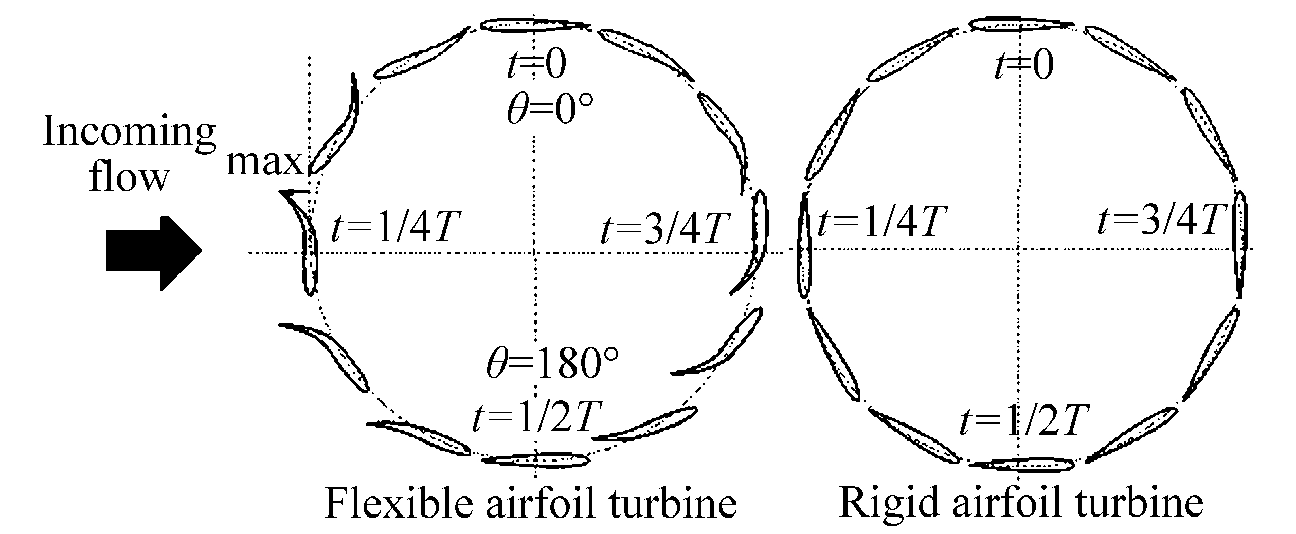
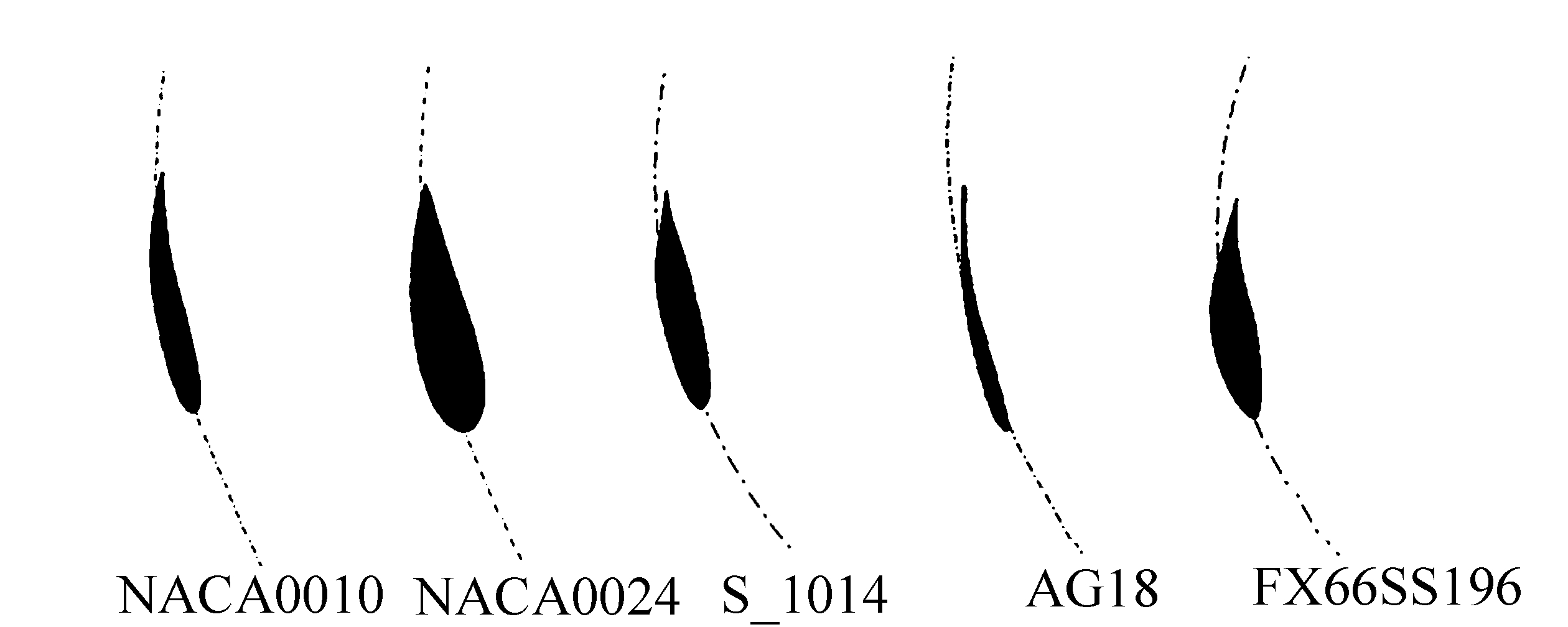
3 Description of model geometry and its motion modelingIn the present study, time-dependent viscous flows around a VATT with a flexible NACA0010 airfoil for energy extraction are simulated (Fig. 1). As mentioned previously, five different flexible airfoils (Symmetric and Non-symmetric) are employed, Fig. 2 shows the shapes and types of the flexible airfoils.
|
| Figure 1 Geometric characteristics of airfoil models |
|
| Figure 2 Photographs of flexible airfoils shapes at θ=100° |
Naturally, for a flexible VATT, the turbine blade has synchronous pitching and rotating motions in addition to flexure motion. Thus, the system is governed by the following equations:
| $\left\{ {\begin{array}{*{20}{c}} {{\theta _t}\left(t \right) = {\theta _0}\sin \left({\omega t - \frac{{\rm{\pi }}}{2}} \right)}\\ {{\omega _t}\left(t \right) = {\beta _0}\sin \left({{f^*}*\omega t - \frac{{\rm{\pi }}}{2}} \right)} \end{array}} \right.$ | (4) |
where
Instantaneous time, flapping frequency, turbine radius, and blade chord-length are used to model deformation of the flexible blade.
Relative to the turbine center (coordinate system), the profile of the flexible airfoil is given by the following equations:
Along the x axis
| $y\left(t \right) = - \frac{{{a_0}}}{c}{\left({x\left({{y_f}, t} \right) - {l_c}} \right)^2}\left({{\rm{sin}}\left({\omega t + \varphi } \right)} \right)$ | (5) |
and along the y axis
| $x\left(t \right) = - \frac{{{a_0}}}{c}{\left({y\left({{x_f}, t} \right) - {l_c}} \right)^2}\left({{\rm{sin}}\left({\omega t + \varphi } \right)} \right)$ | (6) |
where a0 denotes flexure amplitude and φ denotes phase angle. x(yf, t) denotes instantaneous airfoil position along the x-axis, y(xf, t) denotes instantaneous foil position along the y-axis, and t denotes time.
xf and yf are the local coordinates of the airfoil relative to the pitching axis.
Instantaneous deflections of the airfoil along the x-and y-axes are defined as
| $x\left({{y_f}, t} \right) = {a_t}(y){\rm{sin}}\left({\omega t + \varphi } \right)$ | (7) |
| $y\left({{x_f}, t} \right) = {a_t}(x){\rm{sin}}\left({\omega t + \varphi } \right)$ | (8) |
where at(x) and at(y) are deflection amplitudes along the x-axis and y-axis, respectively.
For a blade with a flexible trailing edge, deflection amplitudes are given as
| ${a_t}\left(x \right) = \left[ { - \left({c - {l_c}} \right) * {{\left({\left({\frac{x}{{c - {l_c}}} - R} \right) * {\rm{cos}}({\theta _t})} \right)}^n}} \right] * {a_0}$ | (9) |
| ${a_t}\left(y \right) = \left[ { - \left({c - {l_c}} \right) * {{\left({\left({\frac{y}{{c - {l_c}}} - R} \right) * {\rm{sin}}({\theta _t})} \right)}^n}} \right] * {a_0}$ | (10) |
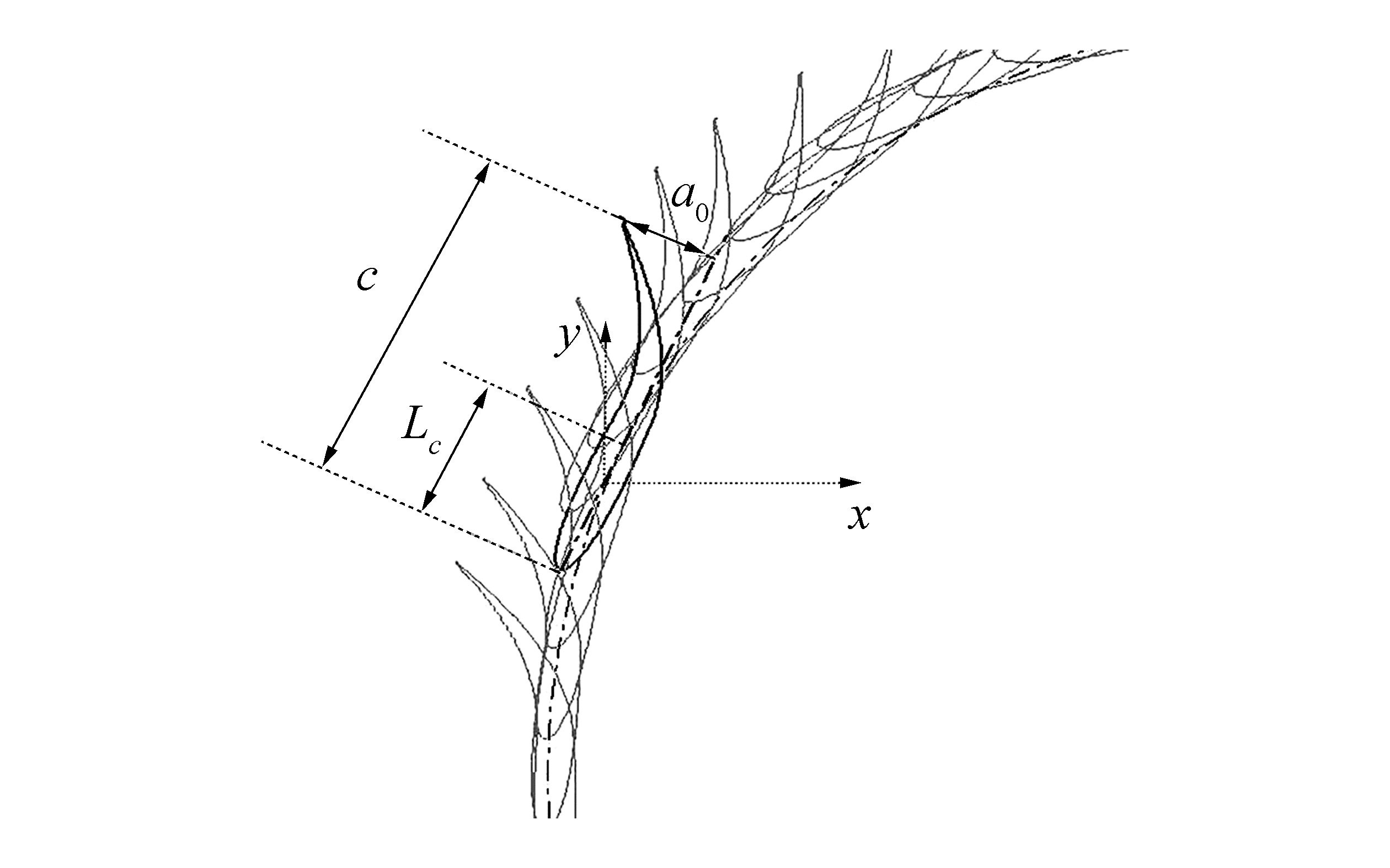
where a0 denotes foil displacement (amplitude) at the trailing edge, as shown in Figure 3, φ denotes phase angle, R turbine radius, c chord length, lc pitching center, and n flexibility coefficient.
|
| Figure 3 Flexible airfoil deformation over time for f*=2 |
Turbine azimuthal angle (θ) is computed from the positive x-axis, as shown in Fig. 1.
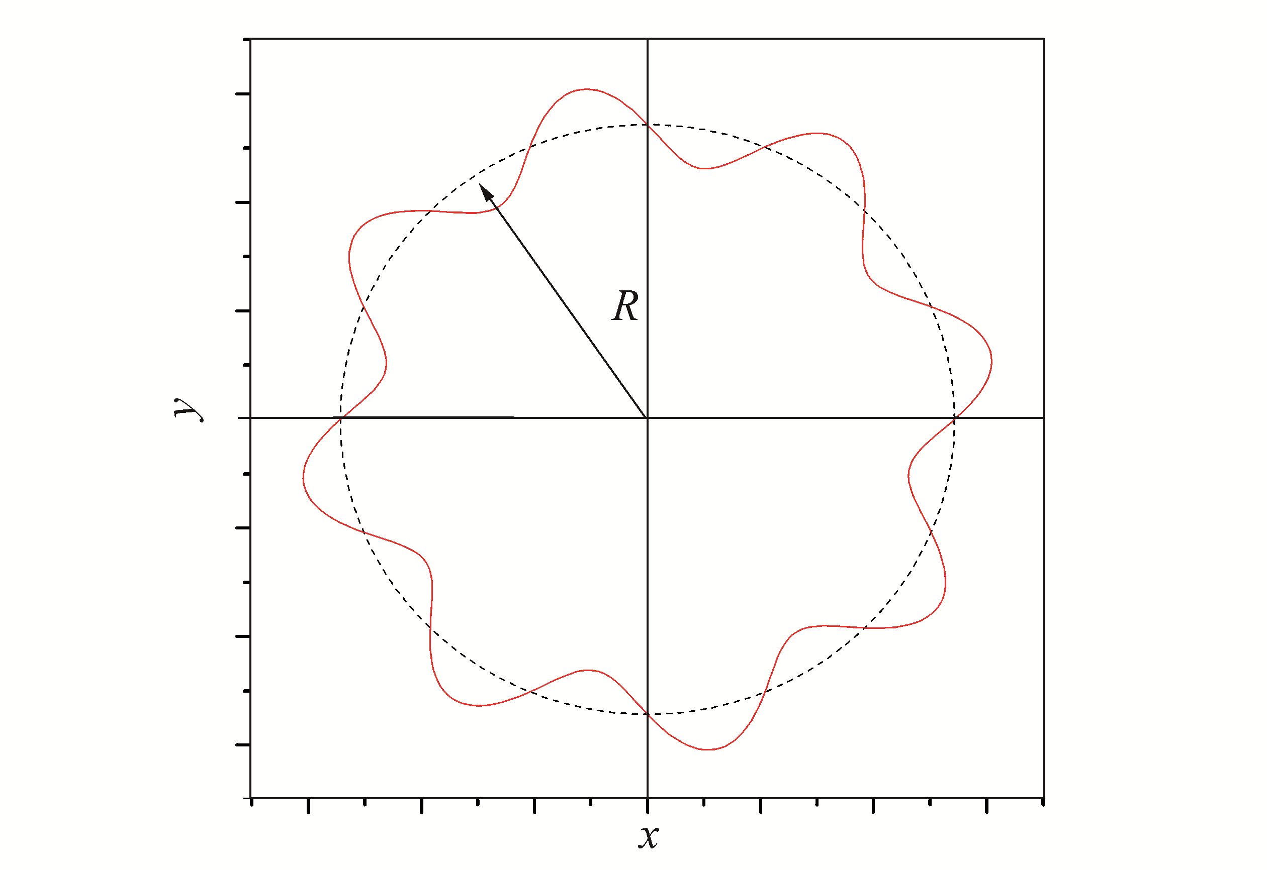
Flexure frequency is quantified relative to turbine diameter by the number of periods of sinusoids f* (non-dimensional frequency) (See Fig. 4). The oscillating amplitude lies between a0/c=0.1 and 0.2, and flexure frequency f* lies between 4 and 8. The dynamic mesh remeshing technique was used. The selected parameters are listed in Table 1.
|
| Figure 4 Flexure motion trajectory f*=8 |
| Minimum length scale | 0.000 01 |
| Maximum length scale | 0.000 05 |
| Maximum cell skewness | 0.67 |
| Size remeshing interval | 6 |
| Spring constant factor | 0.3 |
| Boundary node relaxation | 1 |
| Convergence tolerance | 0.001 |
The present fluid domain (Fig. 5) was extended 37 rotor diameters left and 60 rotor diameters right (practically the same grid dimensions as those used by Castelli et al. (2011)). Two symmetry boundary conditions were used for the upper and the lower side limits. For all solid boundaries, the stationary wall boundary was nominated (no slip condition)

|
| Figure 5 Simulation domain and boundary conditions |
To guarantee continuity in the flow field between the fluid domains, we adopted the interface condition. An inlet velocity condition was applied to the inflow boundaries, and an outlet pressure condition was applied to the outflow boundaries. The considered mesh consisted of 142.345 triangular cells. The turbine was operated at different angular velocities for a constant current velocity of 3 m/s.
For the employed grid near the wall, the dimensionless wall value, defined as follows, was used:
| ${y^ + } = \frac{{{u_\tau } \times y}}{\nu }$ | (11) |
where y is distance from the wall at cell center, and ν is kinematic viscosity (1×10⁻⁶m2/s for water).
In this study, we employed the analogous mesh strategy put forth by Amet et al. (2009). For a similar Reynolds number, by using a k-w model, Amet et al. (2009) investigated the flow around a VAWT. The airfoils were surrounded with a finer mesh in which y+ at the wall adjacent cell was chosen to be around 1, corresponding to a cell size of 25 μm
5 Numerical methodologiesUnsteady incompressible flow is governed by the Navier-Stokes equations, which can be written in the following form:
| $\rho \left[ \frac{\partial \mathbf{V}}{\partial t}+\left(\mathbf{V}\cdot \nabla \right)\mathbf{V} \right]=-\nabla P+~\nabla \cdot \overline{\overline{\tau }}+\rho \mathbf{f}\text{, }\nabla \mathbf{V}\text{=0}$ | (12) |
where V denotes the velocity vector, t instantaneous time, P pressure, μ dynamic viscosity, f body force per unit mass, and
Several authors have proved that the realizable k-ε turbulence model is suitable for solving problems involving rotating blades (Xiao et al. 2013). Therefore, we used it in the present investigation.
The realizable k-ε turbulence model was developed by Shih et al. (1995), and it contains a new transport equation for determining the turbulent dissipation rate. In the standard k-ε model, the model coefficient denoted Cm, is a constant; however, in the realizable k-ε model, this coefficient is expressed as a function of turbulence properties, and this behavior is consistent with the "realizability" of turbulence. The transport equations for k and ε in the realizable k-ε model are:
| $\begin{array}{l} \frac{\partial }{{\partial t}}\left({\rho k} \right) + \frac{\partial }{{\partial {x_i}}}\left({\rho k{u_j}} \right) = \\ \frac{\partial }{{\partial {x_i}}}\left[ {\left({\mu + \frac{{{\mu _t}}}{{{\sigma _k}}}} \right)\frac{{\partial k}}{{\partial {x_j}}}} \right] + {G_k} + {G_b} - \rho \varepsilon - {Y_M} + {S_k} \end{array}$ | (13) |
and
| $\begin{array}{l} \frac{\partial }{{\partial t}}\left({\rho \varepsilon } \right) + \frac{\partial }{{\partial {x_j}}}\left({\rho \varepsilon {u_j}} \right) = \frac{\partial }{{\partial {x_j}}}\left[ {\left({\mu + \frac{{{\mu _t}}}{{{\sigma _\varepsilon }}}} \right)\frac{{\partial \varepsilon }}{{\partial {x_j}}}} \right] + \\ \rho {C_1}{S_\varepsilon } - \rho {C_2}\frac{{{\varepsilon ^2}}}{{k + \sqrt {\upsilon \varepsilon } }} + {C_{1\varepsilon }}\frac{\varepsilon }{k}{C_{3\varepsilon }}{G_b} + {S_\varepsilon } \end{array}$ | (14) |
where
| ${C_1} = {\rm{max}}\left[ {0.43, \frac{\eta }{{\eta + 5}}} \right]$ | (15) |
and
| $\eta = S\frac{k}{\varepsilon }$ | (16) |
In these equations, k is the turbulent kinetic energy, and ε is the rate of dissipation of kinetic energy.
Gk is the generation of turbulence kinetic energy due to mean velocity gradients. Gb is the generation of turbulence kinetic energy due to buoyancy. YM is the contribution of fluctuating dilatation to the overall dissipation rate. Sk and Sε are user-defined source terms. σk and σε are turbulent Prandtl numbers for k and ε, respectively. μt is turbulent viscosity. C1ε, C2, and C3ε are constants in the model. The Realizable k-ε model usually shows improved results for swirling and separating flows as compared to those achieved with the standard k-ε model.
We performed numerical simulation using Ansys-Fluent 15.0. The SIMPLE algorithm was used for pressure-velocity coupling. All transports equations were discretized using the finite-volume method with the second-order upwind scheme for all transport equations. Within a temporal iteration, a User-Defined Function (UDF) is used to control the dynamic mesh and the motion of flexible blades.
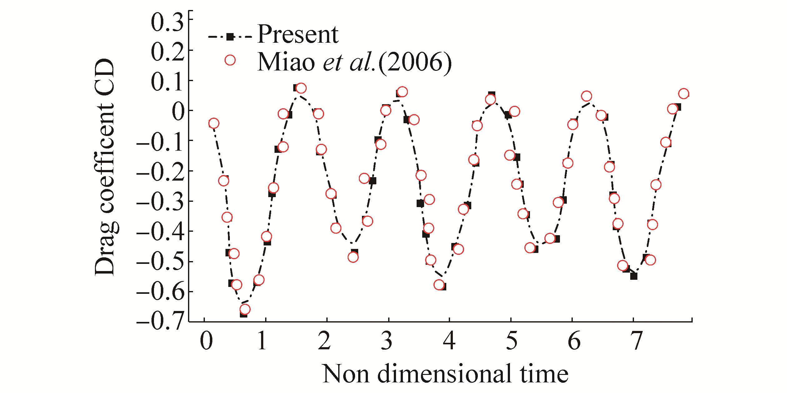
6 Results 6.1 Solver validationThe current solver was validated in first step by simulating a flexible wing in plunging motion, as studied by Miao and Ho (2006). In their investigation, the effect of chord-wise flexure amplitude on unsteady aerodynamic characteristics was considered. Fig. 6 shows the variation of instantaneous drag coefficient for a reduced frequency k=ωc/U∞=2, non-dimensional plunge amplitude h0=0.4, and Reynolds number Re=104 The results show that a thrust force is generated, which corresponds to a reverse Kármán vortex street. It is obvious that the results obtained with the current solver compare well with those of Miao and Ho (2006).
|
| Figure 6 Validation of computational model by comparison with published results |
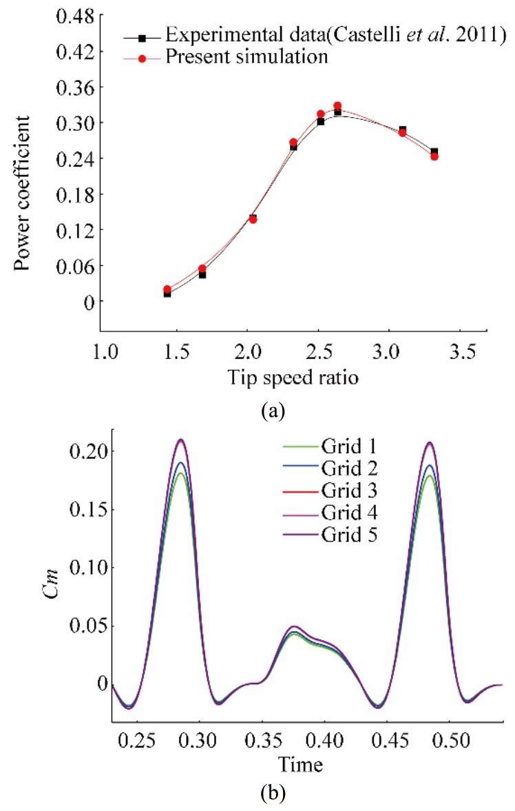
In the second step, for best prediction of the turbine blade instantaneous momentum coefficient, a mesh size dependence test (Fig. 7a) was performed. For several grids of increasing density, the test confirmed that a grid containing about 142.000 cells can predict accurately the momentum coefficient and fluid fields. After a time-step size test, a constant time-step equal to 10-4 s was selected.
|
| Figure 7 (a) Validation of computational model against published results. (b) Instantaneous moment coefficients (grid-dependent test). |
To prove that the present solver can handle rotating blade problems, the computational results obtained herein are compared with those of Castelli et al. (2011). As can be seen from Fig 7(b), there is good agreement between the two sets of results. The numerical results are the mean of data averaged over the last three revolutions. Steadiness was attained typically after approximately three to four rotor revolutions, which is the same as the trend presented by Maȋtre et al. (2013).
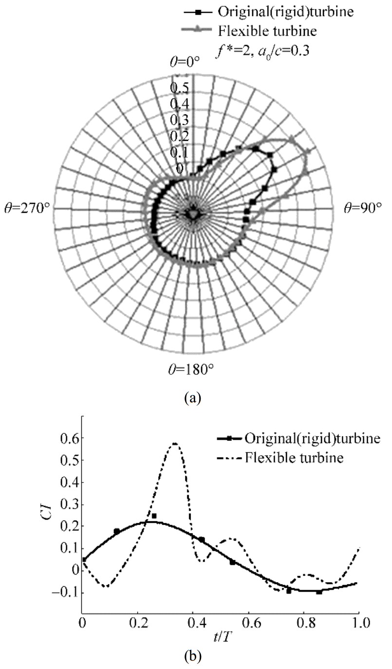
6.2 Mechanism of turbine performance improvementIt is well known that the flexibility of flapping wings can provide improved energy extraction performance, which can never be achieved with rigid wings. To inspect the mechanism by which flexible wings influence turbine performance, a comparison between a rigid blade turbine and a flexible blade turbine in terms of instantaneous blade lift coefficient, torque coefficient, and pressure distribution was made. Figures 8(a) and (b) show, respectively, the instantaneous moment coefficients and the instantaneous blade lift coefficients against time. As can be seen in the figures, the flexible blade generates a larger lift and momentum than the rigid blade. The lift peak increases from 0.2 (rigid) to 0.55 (flexible) and the momentum peak from 0.2 (rigid) to 0.3 (flexible). This behavior is attributed to the stability of leading/trailing edge vortices and shedding (Zhu 2007, Liu et al. 2013). It is generally accepted that a wing with a flexible trailing edge can boost the size and strength of LEV. When the LEV grows, a suction zone is formed simultaneously, which typically increases the pressure difference between the upper and the lower surfaces of the foil. Thus, power-extraction efficiency can be improved by increasing the peaks of lift and moment coefficients.
|
| Figure 8 Comparison of (a) instantaneous moment coefficients and (b) instantaneous blade lift coefficient against time for different blade turbines |
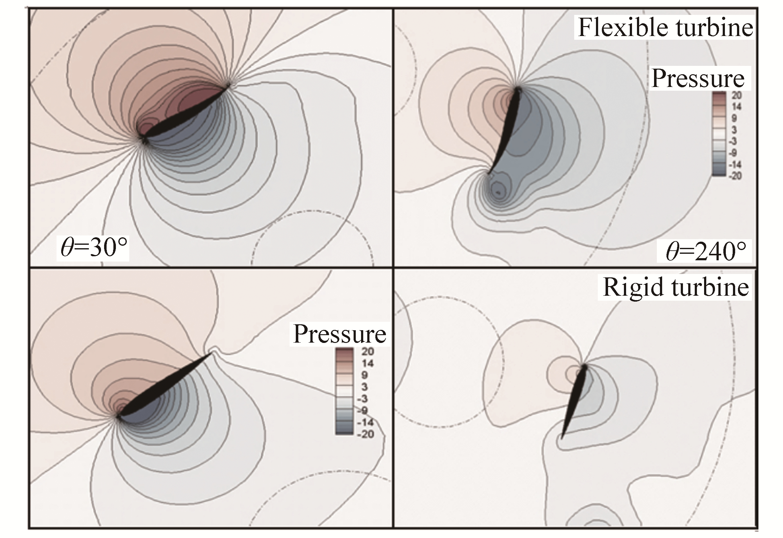
Fig. 9 shows the pressure contours of the rigid and the flexible blades at two azimuthal position θ=30° and θ=240°. As can be seen in the figure, a smaller vortex appears at the trailing edge and sheds quickly in the near wake, and as this vortex dissipates, a new vortex begins to form at the trailing edge due to flexure. This behavior ensures the presence of a source of suction zones that can effectively improve lift and momentum forces.
|
| Figure 9 Comparison of blade surface pressure coefficient distributions |
|
| Figure 10 Effect of oscillation amplitude on instantaneous power coefficients a0/c=0.3, λ=0.7 |
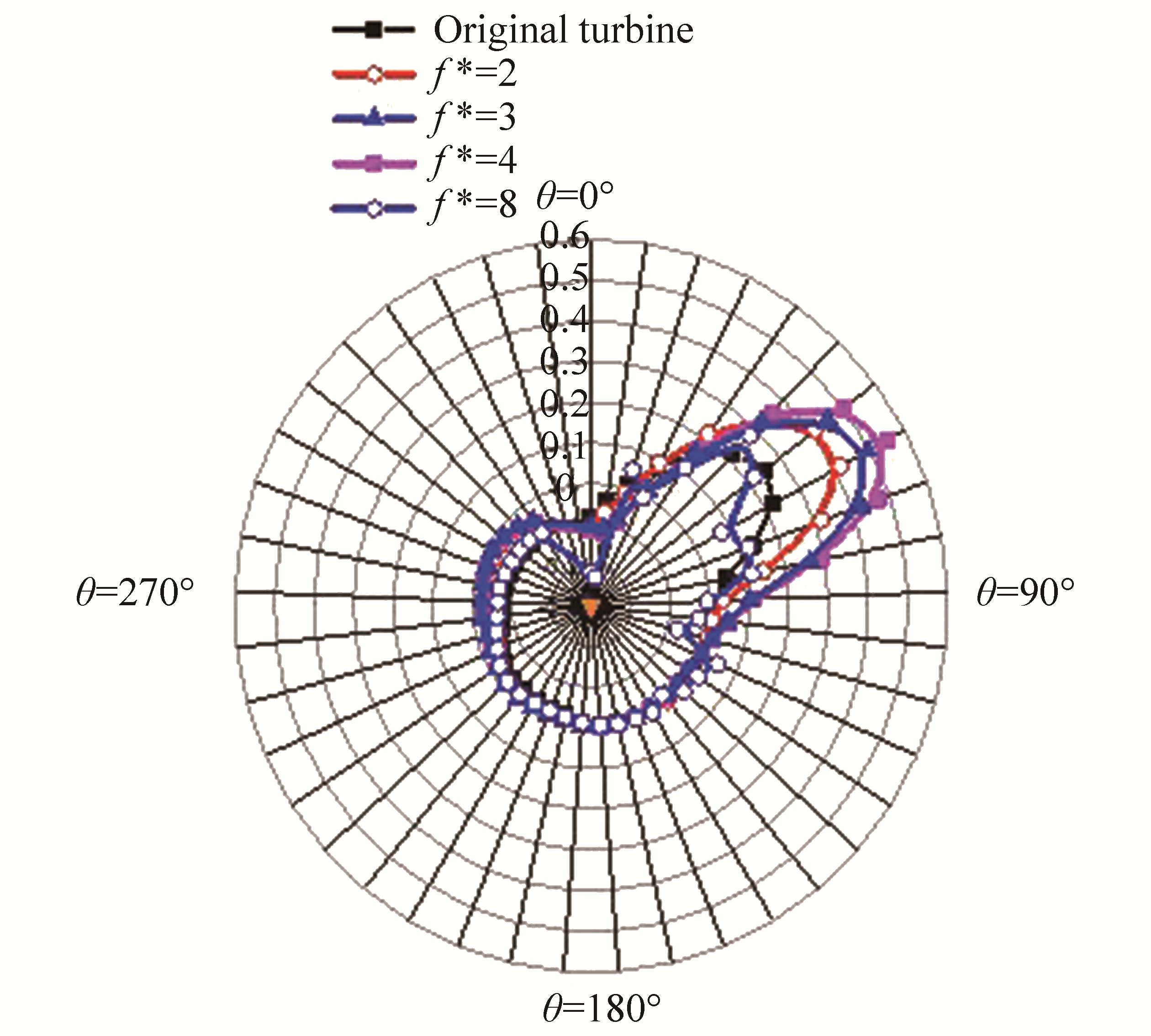
The effect of oscillating frequency on the instantaneous power coefficient is shown in Fig. 10. It is clear that flexible blades can improve power extraction as compared to rigid blades. The mean power coefficient higher of all flexible curves is higher than that of rigid blade curves. It can also be seen that the maximum peak Cp of 0.32 is achievable with an oscillating frequency f*=4, which is about 35.5% that of rigid blade. No improvement in the mean power coefficient is seen with increasing oscillating frequency owing to the occurrence of large-scale vortices between the two rotating blades. A comparison of the vortex contours is shown in Fig. 11. More chaotic and complicated vortex interaction is observed between the two rotating blades with increasing oscillating frequency, which is not preferable in terms of performance.

|
| Figure 11 Effect of oscillation frequency on flow behavior of NACA0010 airfoil (a) f*=4, (b) f*=16. |
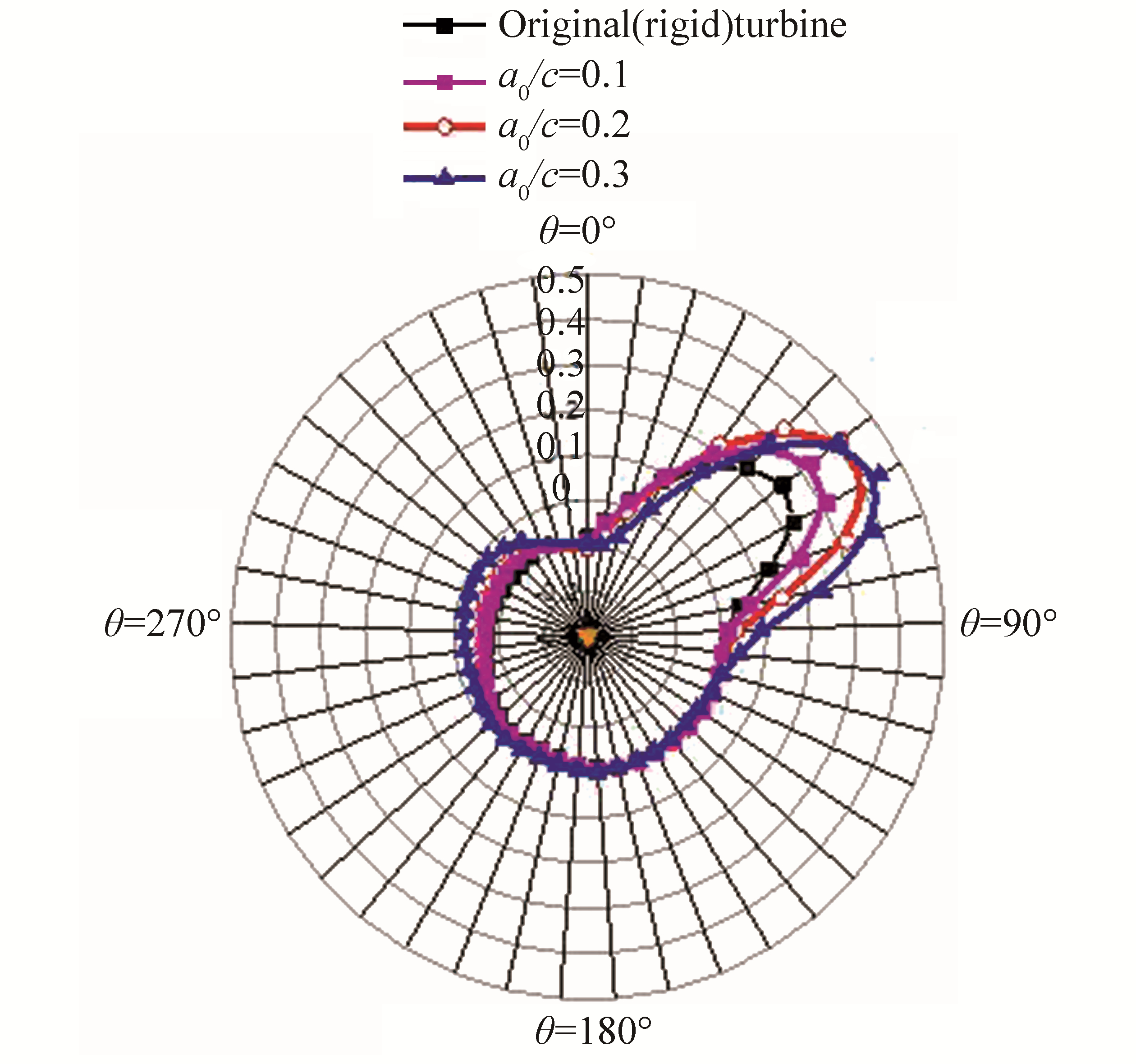
The effect of oscillation amplitude effect on the output power is shown in Fig. 12. For a NACA0010 airfoil, the maximum peak power coefficient is observed for a0/c=0.1. From Fig. 12, it can be seen that with increasing oscillation amplitude, the peak power coefficient remains the same, but large negative peaks occur along the curve, which contribute negatively to the mean power coefficient. The best performance is achieved with an oscillating amplitude a0/c=0.1, which is about 35.5% that of rigid blade.
|
| Figure 12 Effect of oscillation amplitude on instantaneous power coefficients f*=4, λ=0.7 |
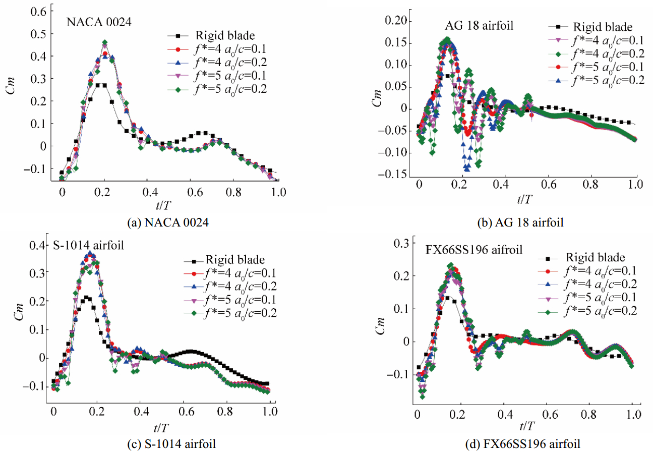
As stated previously, the present work investigates the effect of flexible airfoil shapes on the performance of VATTs. Thus, symmetric (NACA0024, NACA 0010) and non-symmetric (AG18, S_1014, FX66SS196) airfoil shapes were employed. For select oscillation amplitudes and frequencies, the effects of different airfoil types on the instantaneous moment coefficients are shown in Fig. 13(a)-(d) for a comparison of cases, general observations can be addressed:
|
| Figure 13 Instantaneous moment coefficients of different airfoils f*=4, λ=0.7 |
All flexible blades generate higher torque than rigid blades. By increasing the flexure oscillation frequency, additional peaks appear in the torque curve owing to vortex shedding (see Fig. 11), and no improvement in the mean torque coefficient is registered. Therefore, a high flexure frequency is not recommended for turbines with flexible blades. More chaotic and complicated vortex interaction is observed between the two rotating blades with increasing oscillation frequency (Fig. 11).
For both rigid and flexible blades, turbines made of the symmetric NACA0024 airfoil generate the highest torque compared to the symmetric NACA0010 airfoil. This means that airfoil thickness significantly influences turbine performance with or without the new concept of flexibility. Moreover, compared to non-symmetric airfoils, symmetric airfoils generate wider torque curves, which means that stall can be delayed by using symmetric airfoils. A flexible thin airfoil (AG18) is absolutely not preferable over a rigid blade. The maximum instantaneous Cm coefficient of NACA0024 is 0.45, which is about 55% that of the NACA0024 rigid blade turbine. The NACA0024 rigid blade turbine (without flexion) performs better than the AG18 and FX66SS196 flexible or rigid turbines. Increases of 30%, 66.66%, 51.11%, and 22.22% in the torque coefficient compared, respectively, to NACA 0010, AG18, FX66SS196, and S_1014 are achievable with the flexible NACA0024 airfoil.
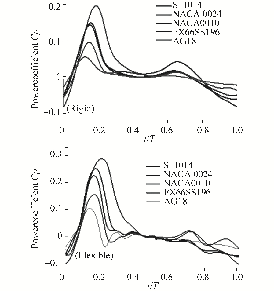
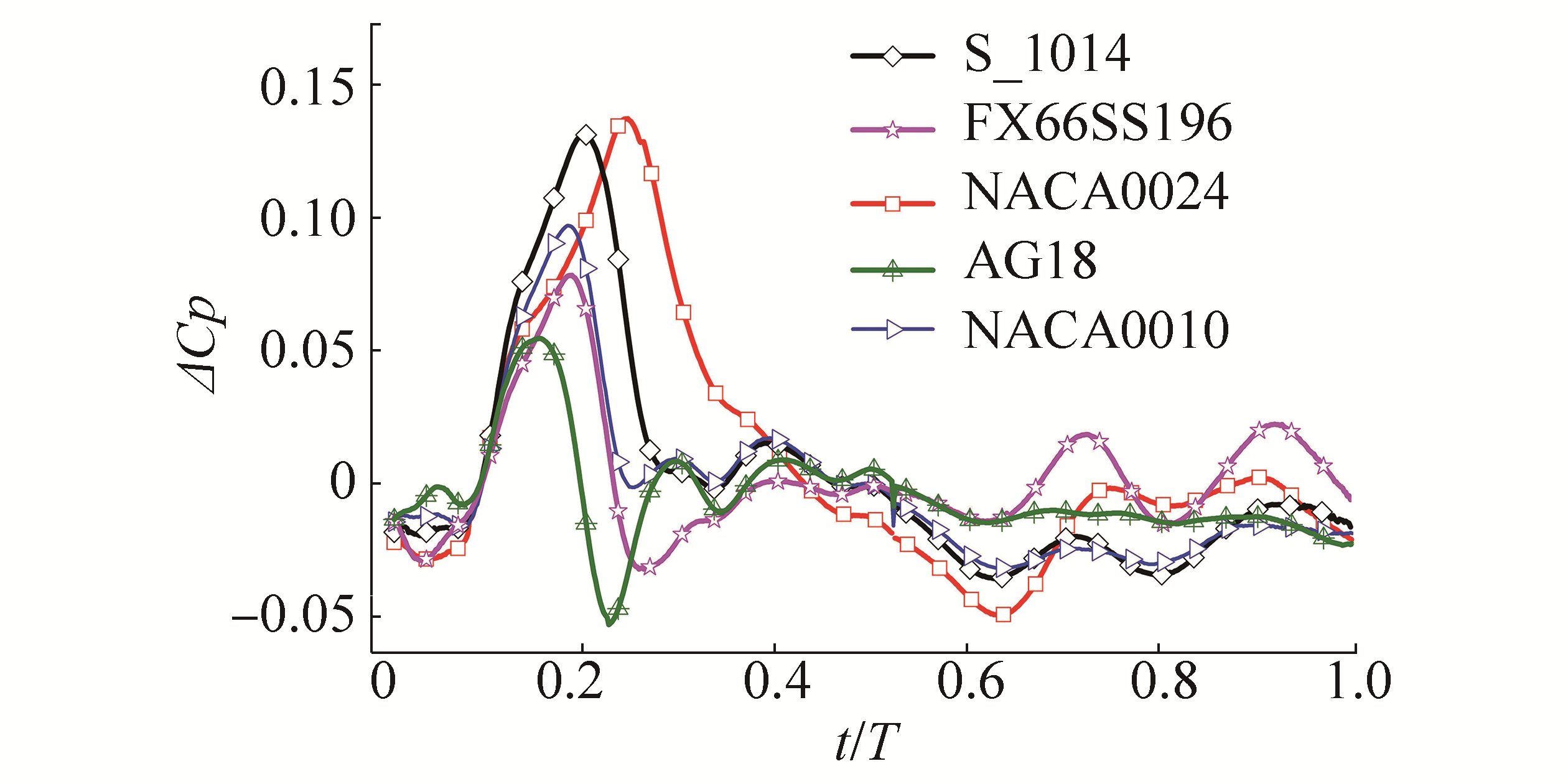
Figure 14 shows (a) the instantaneous power coefficient of rigid airfoils and (b) the maximum instantaneous power coefficient of flexible turbine case corresponding to f*=4 and a0/c=0.1. Typically, the NACA0024 turbine, which has the maximum instantaneous Cm coefficient, will generate the maximum power coefficient. It can be seen that the power coefficient is shifted toward the right by increasing the airfoil thickness, which means that the turbine can extract energy over a large azimuthal angle and, therefore, a large operating range is expected for this configuration. To examine the effect of flexible blade control strategy on the efficiency relative to airfoil types, the gain in power coefficient ΔCp is shown in Fig. 15. It was found that for the two airfoils S1014 and NACA0024, similar gains were registered. Moreover, using flexible blades with the NACA0010 airfoil yields greater improvement in efficiency than that when using flexible blades with the FX66SS196 and the AG18 airfoils.
|
| Figure 14 Instantaneous power coefficients of different airfoils |
|
| Figure 15 Gain in power coefficients of different airfoils |
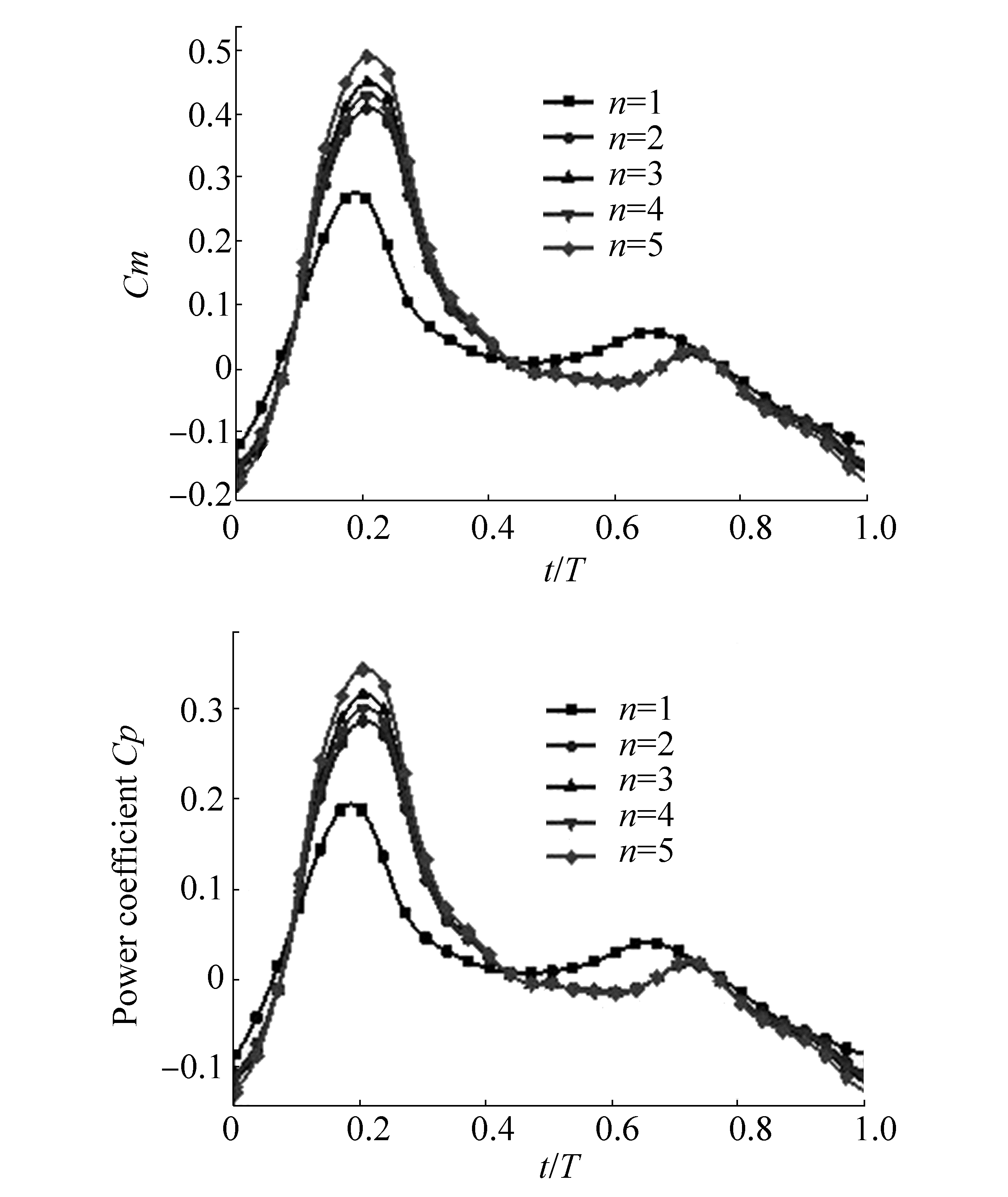
To study the effect of the flexible coefficient n on the output power, we selected the NACA 0024 airfoil. Figs 16(a) and (b) show the effect of blade flexibility on the instantaneous momentum coefficient and the instantaneous power coefficient. As presented in Fig. 16 and Eqs. (8) and (9), the degree of flexibility is controlled by the factor n, where n=1 means a rigid wing. It is seen that all flexible cases yield a higher momentum coefficient than the rigid cases. The results reveal also that the degree of flexibility has a weak influence on the peak power and momentum coefficients. The mean Cp coefficient increased by about 5% when the flexible factor was varied from 1 to 5.
|
| Figure 16 Effect of flexible coefficient n on (a) instantaneous moment coefficients and (b) instantaneous power coefficients (NACA0024) |
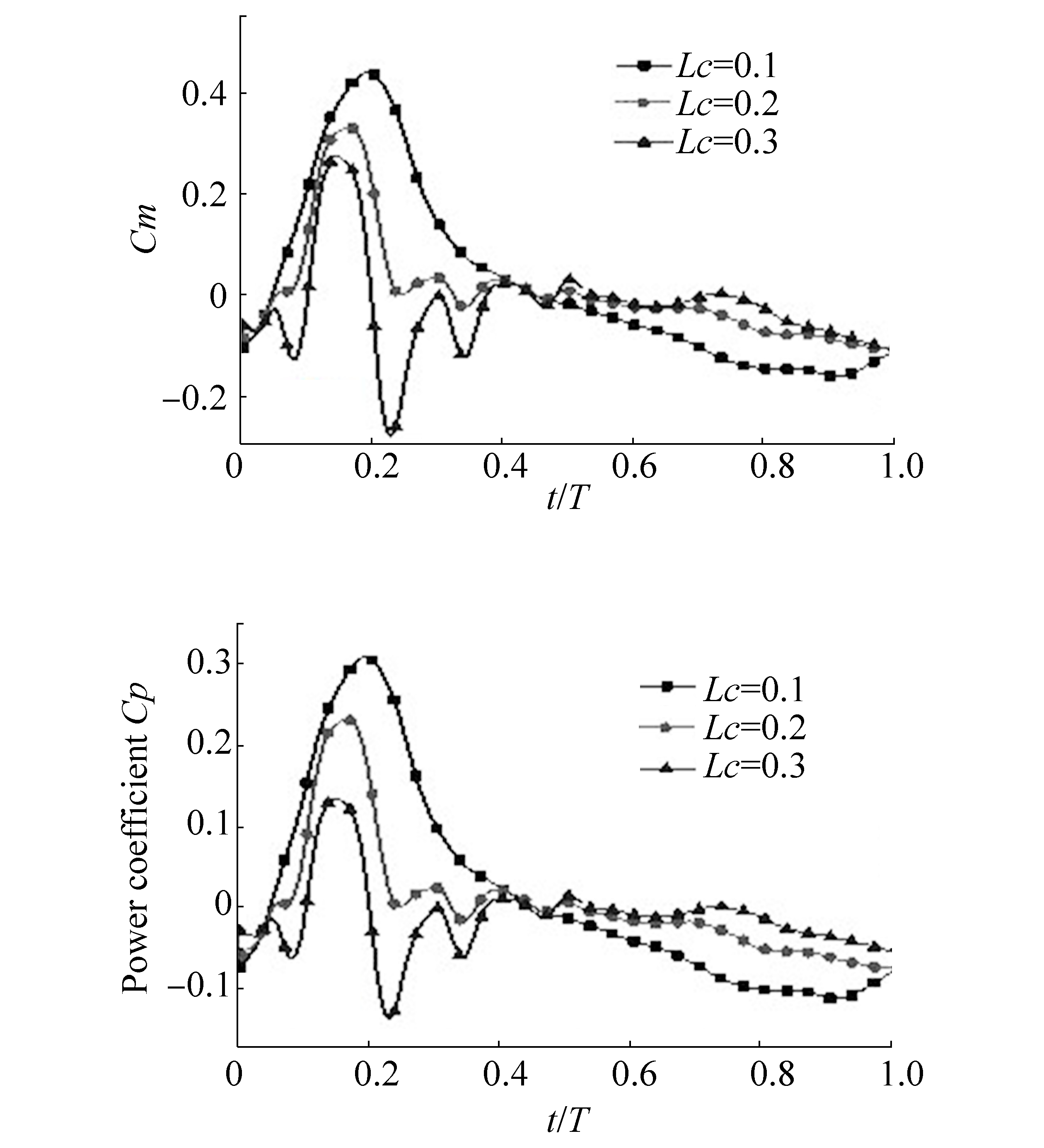
As mentioned in Section 3, flexion is started from a given distance Lc (see Fig. 3). In this section, the effect of the flexible coefficient Lc is shown in Fig. 17. The maximum Cp of 0.3 and Cm of 0.41 is achieved for Lc=0.1, and with an increase in the flexible coefficient Lc from 0.1 to 0.3, the peak Cp and Cm drop, respectively, to 0.23 and 0.33. This behavior is attributed to the mechanism of LEV formation. When a small Lc is selected, the flexible part of the airfoil is long, which leads to effective control of the LEV size and strength.
|
| Figure 17 Effect of flexible coefficient Lc on (a) instantaneous moment coefficients and (b) instantaneous power coefficients (NACA0024, λ=0.7) |
Instead of rigid blade VATTs, this study suggests the use of flexible blades that change their shape throughout turbine rotation. This concept is driven by the amazing mobility of aero/aquatic animals when they use their members to achieve displacement in fluid. The effect of flexible airfoil shapes on VATT performance is considered. Computational results indicate that for the flexible NACA0024 airfoil, the peak power coefficient (Cp) is effectively improved as compared to that of the rigid NACA0024 blade turbine. The results also show that symmetric airfoils perform better than non-symmetric airfoils, leading—in practice—to a wider operating range.
| Amet E, Maître T, Pellone C, ACHARD JL, 2009. 2D numerical simulations of blade-vortex interaction in a Darrieus turbine. Journal of Fluids Engineering, 131(11), 111103. DOI:10.1115/1.4000258 |
| Bandyopadhyay PR, 2004. Biology-inspired science and technology for autonomous underwater vehicles. IEEE Journal of Oceanic Engineering, 29(3), 542–546. DOI:10.1109/JOE.2004.833099 |
| Castelli MR, Englaro A, Benini E, 2011. The Darrieus tidal turbine: proposal for a newperformance prediction model based on CFD. Energy, 36(8), 4919–4934. DOI:10.1016/j.energy.2011.05.036 |
| Fish FE, 2004. Structure and mechanics of nonpiscine control surfaces. IEEE Journal of Oceanic Engineering, 29(3), 605–621. DOI:10.1109/JOE.2004.833213 |
| Lin CS, Hwu C, Young WB, 2006. The thrust and lift of an ornithopter's membrane wings with simple flapping motion. Aerospace Science and Technology, 10, 111–119. DOI:10.1016/j.ast.2005.10.003 |
| Liu W, Xiao.Q, Cheng F, 2013. A bio-inspired study on tidal energy extraction with flexible flapping wings. Bioinspiration and Biomimetics, 8, 036011. DOI:10.1088/1748-3182/8/3/036011 |
| Liu W, Xiao Q, 2015. Investigation on Darrieus type straight blade vertical axis wind turbine with flexible blade. Ocean Engineering, 110, 339–356. DOI:10.1016/j.oceaneng.2015.10.027 |
| Maître T, Amet E, Pellone C, 2013. Modeling of the flow in a Darrieus water turbine: Wall grid refinement analysis and comparison with experiments. Renewable Energy, 51, 497–512. DOI:10.1016/j.renene.2012.09.030 |
| Mazaheri K, Ebrahimi A, 2010. Experimental investigation of the effect of chordwise flexibility on the aerodynamics of flapping wings in hovering flight. Journal of Fluids and Structures, 26(4), 544–558. DOI:10.1016/j.jfluidstructs.2010.03.004 |
| Miao JM, Ho MH, 2006. Effect of flexure on aerodynamic propulsive efficiency of flapping flexible airfoil. Journal of Fluids and Structures, 22(3), 401–419. DOI:10.1016/j.jfluidstructs.2005.11.004 |
| Nakata T, Liu H, 2012. Aerodynamic performance of a hovering hawkmoth with flexible wings: a computational approach. Proc.R. Soc. B, 279, 722–731. DOI:10.1098/rspb.2011.1023 |
| Shih T, Liou WW, Shabbir A, Yang Z, Zhu J, 1995. A new k-ε eddy viscosity model for high Reynolds number turbulent flows. Computers and Fluids, 24(3), 227–238. DOI:10.1016/0045-7930(94)00032-T |
| Shoele K, Zhu Q, 2012. Leading edge strengthening and the propulsion performance of flexible ray fins. J. Fluid Mech., 693, 402–32. DOI:10.1017/jfm.2011.538 |
| Tian FB, Young J, Lai JCS, 2014. Improving power-extraction efficiency of a flapping plate: from passive deformation to active control. Journal of Fluids and Structures, 51, 384–392. DOI:10.1016/j.jfluidstructs.2014.07.013 |
| Wu J, Liu C, Yang YC, Zh ao, 2015. Influence of a flexible tail on the performance of a foil hovering near the ground: Numerical investigation. European Journal of Mechanics B/Fluids, 52, 85–96. DOI:10.1016/j.euromechflu.2015.02.004 |
| Xiao Q, Liu W, Incecik A, 2013. Flow control for VATT by fixed and oscillating flap. Renewable Energy, 51, 141–152. DOI:10.1016/j.renene.2012.09.021 |
| Yu J, Liu L, Tan M, 2008. Three-dimensional dynamic modeling of robotic fish: simulations and experiments. Transactions of the Institute of Measurement and Control, 30(3/4), 239–2580. |
| Zhu Q, 2007. Numerical simulation of a flapping foil with chordwise or spanwise flexibility. AIAA J., 45(10), 2448–2457. DOI:10.2514/1.28565 |


