2. Undergraduate Student of Mechanical Engineering, University of Indonesia, Jakarta 16424, Indonesia
1 Introduction
Competitive advantages are given by multihull vessels instability, payload capability, and resistance in high-speed regimes. To optimize performance, particularly in terms of resistance, multiple aspects relating to these vessels have been studied. The development of multihull ships began with catamarans, progressed to trimarans, and finally evoked new interest in quadramarans and pentamarans.
In catamarans, the interaction between both hulls strongly depends on hull separation and advancement speeds. The interaction shows both value and variation of the total resistance coefficient CT (Broglia et al., 2014). Interestingly, in trimarans, there are no striking differences. The most important factors affecting resistance are outrigger symmetry, their configurations, and cruising speeds. Other factors are likely to offer slight performance improvements (Ackers et al., 1997; Doctors and Scrace, 2003; Sahoo et al., 2004; Hafez and El-Kot, 2011). It has also been confirmed that trimaran performance is strongly dependent on outrigger longitudinal configurations (Peng et al., 2004). However, they are not sensitive to transverse spacing. Furthermore, Tuck and Lazaukas (1998) have tested multiple models of multihull ship configurations. In their study, the outrigger configurations offered an exceptional analysis of interference resistance as well as for tetramaran and quadramaran configurations and agree well with other research results conducted by Yanuar et al. (2016) and Tarafder et al. (2010).
A vessel with five hulls, i.e., a pentamaran, was the result of development from other multihull ships with the purpose of obtaining improved characteristics. It was originally developed in Europe by Gee in 1998 as a fast-freight vessel carrying cargo to replace conventional cargo ships. Other designs and studies also emerged from this innovation, e.g., high-speed ferries for passenger transport, sea lifts for troop transport, patrol boats for coastal defense duties, and fast RORO ships for carrying wheeled cargo (Ikeda and Nakabayashi, 2005).
Like a trimaran, a pentamaran hull arrangement has a similar concept: one mainhull in the center position and an equal number of side hull on its sides, which often called as outrigger These outriggers can be transversely configured inline with the mainhull, longitudinally with its pair, or even with a combination of the transverse and longitudinal configurations. Using a Wigley hull, two variants of the third configuration have been investigated by Peng (2001). In addition, Dudson and Gee (2001) have investigated the second configuration, whereas the first one has been numerically studied by Tarafder et al. (2013).
Apart from the regular configuration, two asymmetric outrigger configurations have been initially proposed and investigated by Ackers et al. (1997): an asymmetric inboard wherein the chine of the side hull is placed inboard and an asymmetric outboard. Thus, asymmetric outboard configurations produce the lowest interference drag between both variations of a trimaran. Moreover, Yanuar et al.(2013, 2015) have experimentally studied the trimaran and pentamaran configurations wherein the outriggers were asymmetric outboard.
As a result of the above research, the transverse and longitudinal configurations as well as symmetric and asymmetric configurations are identified as the essential key parameters controlling multihull ship resistance (Yu et al., 2015). These parameters determine the magnitude of the wave resistance component and hence the amount of interaction between individual wave structures produced by each hull and outrigger (Muscat-Fenech and La-Rosa, 2014)
Despite the considerable research progress in previous investigations, an experimental understanding of the interference resistance of multihull vessels, particularly pentamarans, still remains incomplete. This study aims at partly filling this gap by contributing to the understanding of interference effects for a non-staggered Wigley pentamaran with a pair of symmetric and asymmetric outriggers advancing in calm water and under fixed trim-sinkage conditions. The performance of this ship model is investigated in a towing tank at various values of hull separation for each different asymmetric outrigger configuration and Froude number.
2 Test analysisThe wave component is considerably influences the ship resistance in a high-speed regime. To obtain wave resistance from total resistance, we have to calculate the resistance due to friction. Certainly, air resistance and correlation allowance are ignored in current experimental. The coefficient is used to represent the principle rather than the resistance value itself. For a monohull, the total resistance coefficient can be expressed as follows:
| $ {{C}_{T}}={{C}_{W}}+(1+k){{C}_{f}} $ | (1) |
and for multihull, it can expressed as follows:
| $ {{C}_{T}}=\tau {{C}_{W}}+(1+\beta k){{C}_{f}}, $ | (2) |
where k is the form factor that is assumed similar for both the single and multihull analyses. τ is the wave-resistance interference factor. β is the viscous-resistance interference factor. Those interference factors were derived firstly by Insel and Molland (Insel and Molland, 1992) for catamaran or twinhull, Yet, those are applicable as well as for other multihulls, and it is proven by Interference Factor analysis of total resistance coefficient. The formula can be applied in this experimental case because it was developed based on linearized wave resistance theory and experimentally compared with test data from Wigley hull form at different values of separation ratios. In this experiment we focused on the separation ratio (S/L or transverse distance) and didn't do any modification on longitudinal distance (R/L), thus it met with Insel and Moland basic test condition.
The total coefficient is calculated from the total resistance obtained in the experiments. The friction drag coefficient is computed according to the ITTC 1957 model-ship correlation line formula expressed as follows:
| $ {{C}_{F}}=\frac{0.075}{{{\left({{\log }_{10}}Re-2 \right)}^{2}}} $ | (3) |
The interference factor is then acquired from the wave resistance coefficient of the pentamaran and compared with the sum of the wave resistance coefficient of each single hull.
The interference factor can be often figured by considering the total resistance instead of the wave resistance. In this analysis, we are using the total resistance coefficient (Zaghi et al., 2011). Because of this choice, using the total resistance coefficient removes denominator terms such as friction, wave resistance, and other components in the calculation. Hence, the interference factor IF can be expressed as follows:
| $ IF=\frac{C_{T}^{(P)}-C_{T}^{(M)}}{C_{T}^{(M)}}, $ | (4) |
where
Principally, if possible, the value of the interference factor has to be at a minimum or negative (Souto-Iglesias et al., 2012).
The distance of the model to the wall and bottom of the tank is far enough. So, blockage correction is neglected in this experimental.
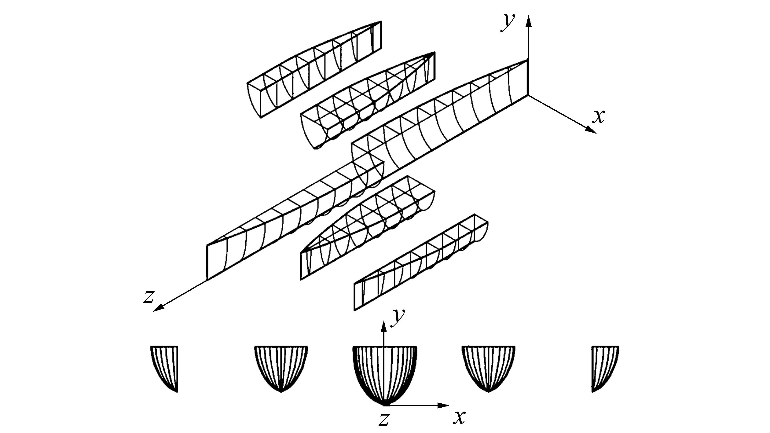
3 Experimental setupThe geometrical characteristics of the pentamaran model are listed in Table 1. The model comprises two asymmetric outriggers along with a pair of symmetric ones, as shown in Fig. 1. The Wigley-type line form is depicted in Fig. 2.
| Particular | Symbol | Subhull | ||
| Center | Side Sym. |
Side Asym. |
||
| Length / m | LoA | 1.8 | 1.35 | 1.35 |
| Beam / m | B | 0.18 | 0.15 | 0.075 |
| Draft / m | T | 0.06 | 0.02 | 0.02 |
| Block coefficient | Cb | 0.44 | 0.435 | 0.433 |
| Waterplane-area coefficient | Cw | 0.708 | 0.74 | 0.739 |
| Prismatic coefficient | Cp | 0.701 | 0.741 | 0.739 |
| Maximum section coefficient | Cm | 0.627 | 0.588 | 0.586 |
| Displacement / kg | Δ | 6.565 | 0.728 | 0.362 |
| Wetted surface area / m2 | Sa | 0.292 | 0.085 | 0.07 |
|
| Figure 1 The pentamaran model |

|
| Figure 2 Line plan of the Wigley-hull form of the pentamaran model |
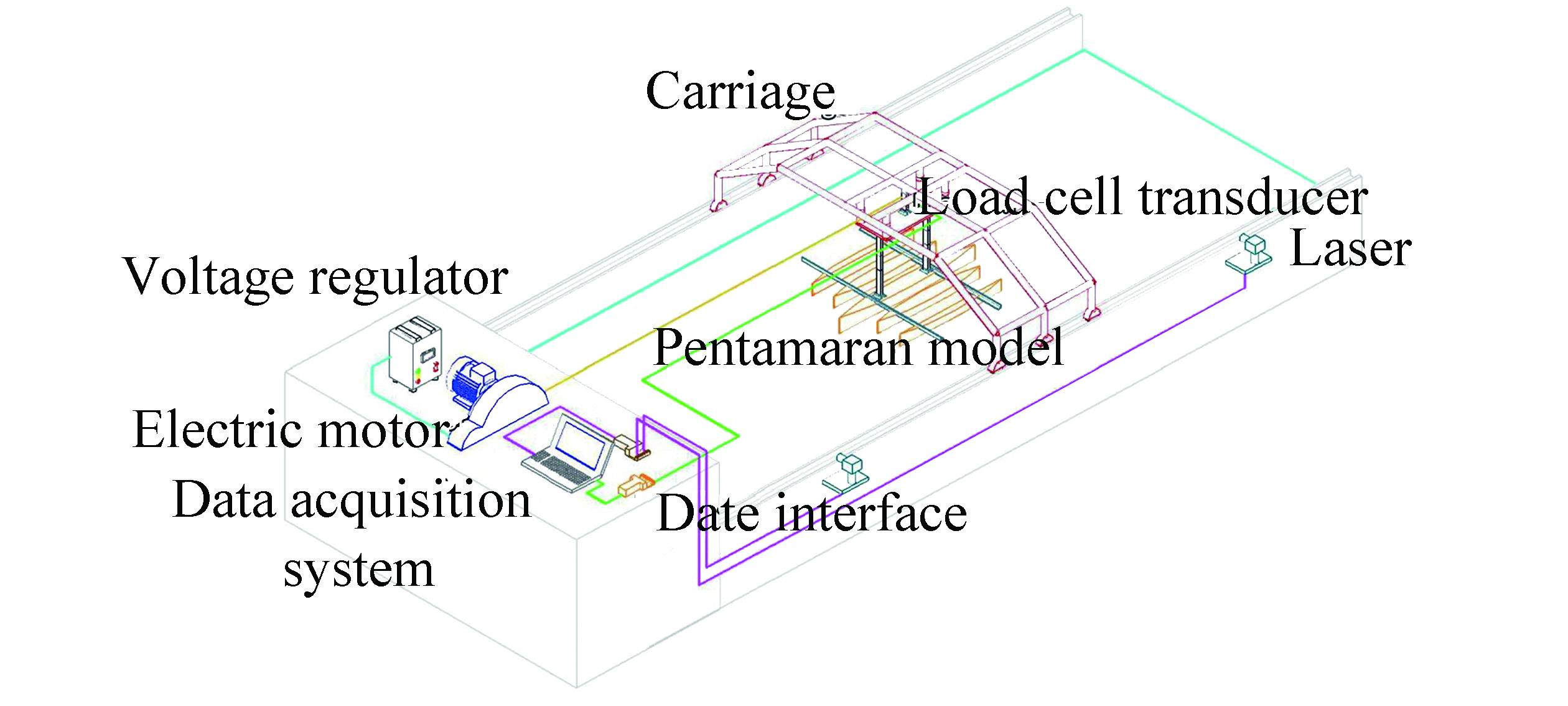
The resistance performance of the ship model has been investigated in a towing tank belongs to Indonesia Hydrodynamic Laboratory (IHL) for three variations of hull separations (transverse distance) in asymmetric outrigger configurations and Froude number ranging from 0.3 to 0.8. The experiment is performed in calm water under a fixed model condition, thereby eliminating the trim and sinkage motion effects. The towing tank is 40m long, 10m wide, and 2m deep. The experimental setup comprises a load cell transducer to measure the total drag of the model along with a computer and LabVIEW software to translate the data from the load cell. The model test is conveyed with a towing carriage that remains at a constant speed and fixed trim condition (see Fig. 3).
|
| Figure 3 Schematic of the experimental setup |
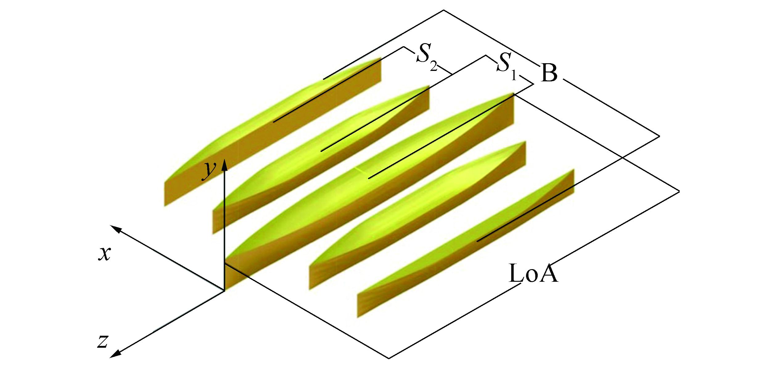
Fig. 4 represents the model geometry and reference system of the pentamaran model. The notation of S1 defines the distance between the center length of the main hull and inner outriggers. For the width between the center length of the inner and outer outriggers, it is symbolized by S2 notation. In this study, the span of S1 is identical to that of S2 and the S symbol is applied to express the space of hull separations. The main dimensions of each hull are listed in Table 1.
|
| Figure 4 The model geometry and reference system of the pentamaran model |
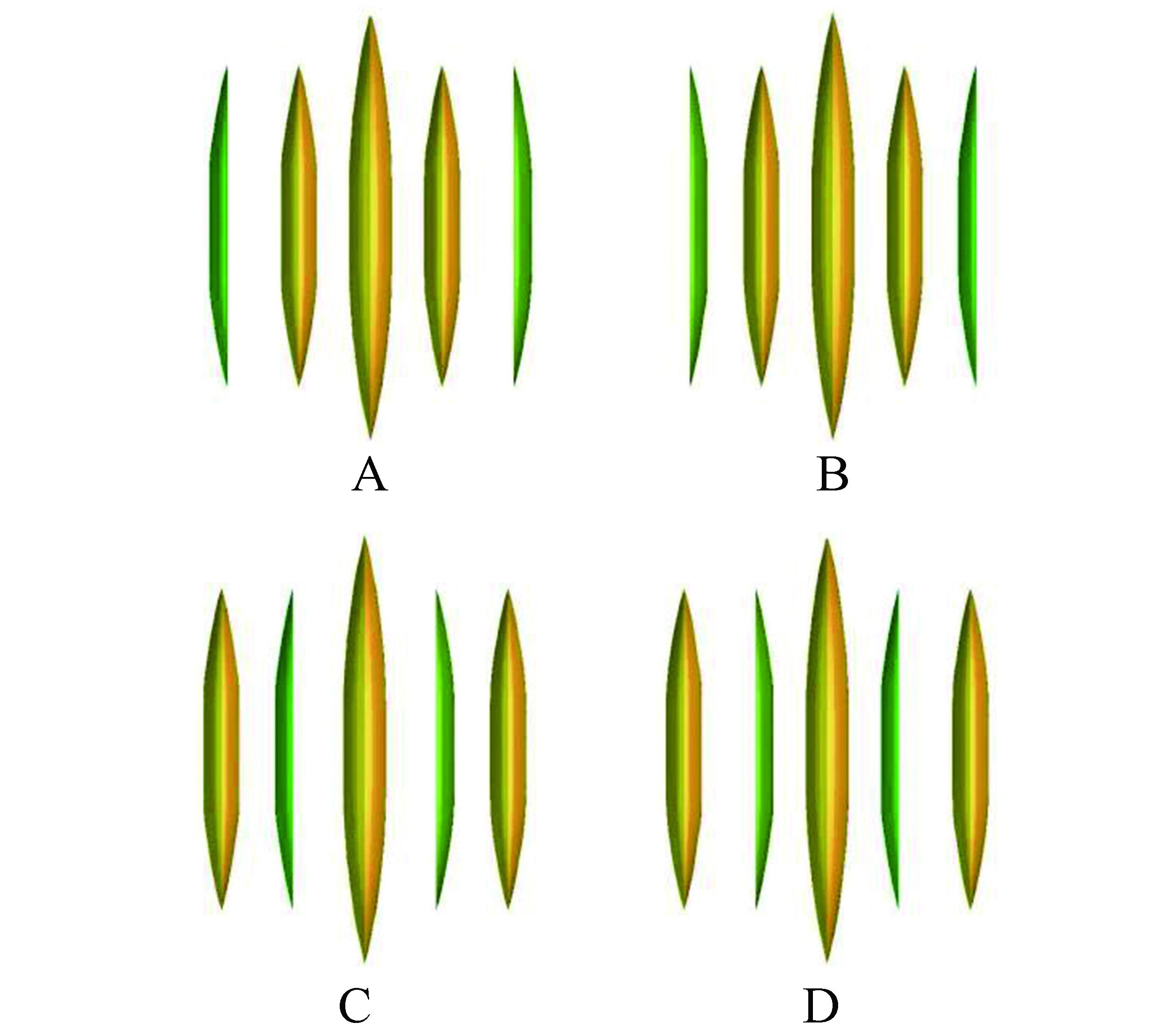
The asymmetric part of the outriggers was configured in an equivalent place for four different configurations (see Fig. 5):
|
| Figure 5 Configurations of asymmetric outriggers. |
A. Outer position: asymmetric outboard
B. Outer position: asymmetric inboard
C. Inner position: asymmetric outboard
D. Inner position: asymmetric inboard
The three variations of the outrigger transverse distance are summarized in Table 2. Each configuration has the same hull separation ratio that is defined as S/L.
| Configuration | S/L Ratio | ||
| 1 | 2 | 3 | |
| A | 0.22 | 0.28 | 0.33 |
| B | 0.22 | 0.28 | 0.33 |
| C | 0.22 | 0.28 | 0.33 |
| D | 0.22 | 0.28 | 0.33 |
The total resistance is majorly influenced by the viscous and wave resistance components. The viscous resistance may break down into the dominant part of frictional resistance that is affected by the form factor. Additionally, the wave resistance can be separated into two components: wave-breaking resistance and wave-induced resistance. Additionally, there are phenomena known as hump and hollow that occur at specific speeds and are generated by the interference of waves on a multihull vessel. A hump is formed by constructive wave interference that increases wave resistance, whereas a hollow is formed by destructive wave interference that decreases the wave resistance.
These phenomena are interesting because the wave resistance dominates in high-speed regimes. By making a hollow, the decreased wave resistance also decreases the total ship resistance, significantly reducing the power consumption. Consequently, we can claim an optimum configuration for the hollow that has the smallest resistance value, CT.
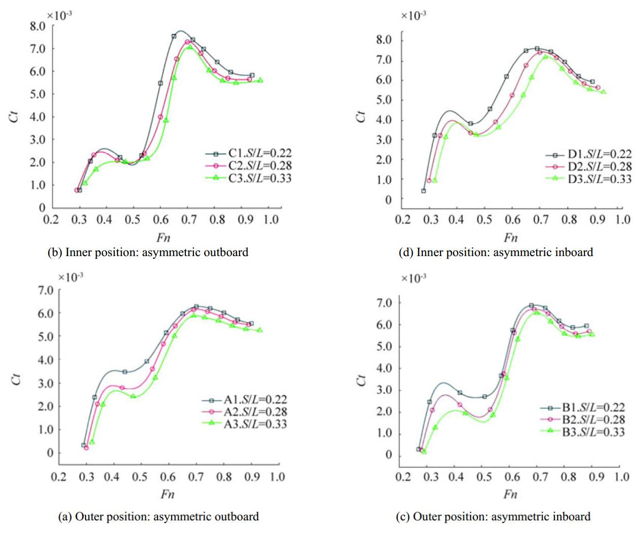
Fig. 6 shows a graph of the total resistance coefficients as a function of the Froude number. The S/L ratio throughout each configuration appears to produce a similar trend. The shortest hull separation of S/L=0.22 seems consistently inferior over the Froude number span. The longest separation of S/L=0.33 is the lowest resistance among the curves and indicates that wider separation (bigger S/L ratio) contribute to a decrease in ship resistance as well as reduce the hump. This effect is also described by Souto-Iglesias et al. (2012).
|
| Figure 6 Total resistance coefficient in all asymmetric outrigger configurations |
Generally, the curve of each entire configuration has comparable characteristics. They have incremental and decremental motions through the complete speed range of this investigation. From the start point, they tend to rise from low to medium speed of Fn=0.4 and fall to their first hollow. In the high-speed regime, they again rise up to the second hump roughly at Fn=0.7. Then, their slopes invert to a decreasing direction and indicate less contributions of resistance at a high Fn value, leading to reduced hump sizes. At the highest speed, this effect shows a convergence between the experimental results and the results of Tuck (1998) and Yanuar et al. (2016).
4.2 Resistance curve for all hull separationsFigure 7 shows the total resistance coefficient curves for each hull separation. Interestingly, there is no configuration that stands out as optimal over the entire speed range while at the same transverse distance.

|
| Figure 7 Total resistance coefficient in all transverse distance variations |
The outer outrigger position: asymmetric inboard arrangement has the lowest resistance when compared to the others, particularly in the medium-speed regime. Yet, for the high-speed regime, the inner outrigger position: asymmetric outboard configuration knocks it on S/L=0.33. In the high-speed regime, the outer outrigger position: asymmetric outboard layout has the lowest resistance, which means that it is the best choice for high-speed operations. Unfortunately, it has high drag mainly in low-to-medium-speed ranges. These results are similar to those obtained in Wigley-hull experiments by Peng (2001), asymmetric outriggers by Ackers (1997), and by Yanuar (2015).
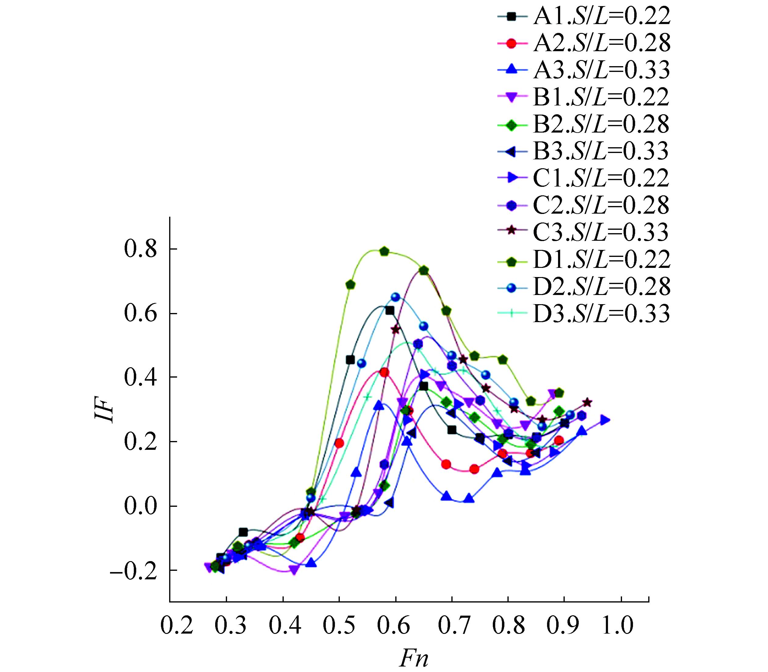
4.3 Interference factorUsing the total resistance coefficient curves presented earlier, the interference factor for all configurations of the model as a function of the Froude number are described in Fig. 8. A minimum or negative interference factor indicates a beneficial one, whereas a positive value indicates a detrimental interference. For the finest interference performance, we may conclude that there is no outstanding configuration that knocks other configurations over the entire speed region.
|
| Figure 8 Interference factor for all hull configurations |
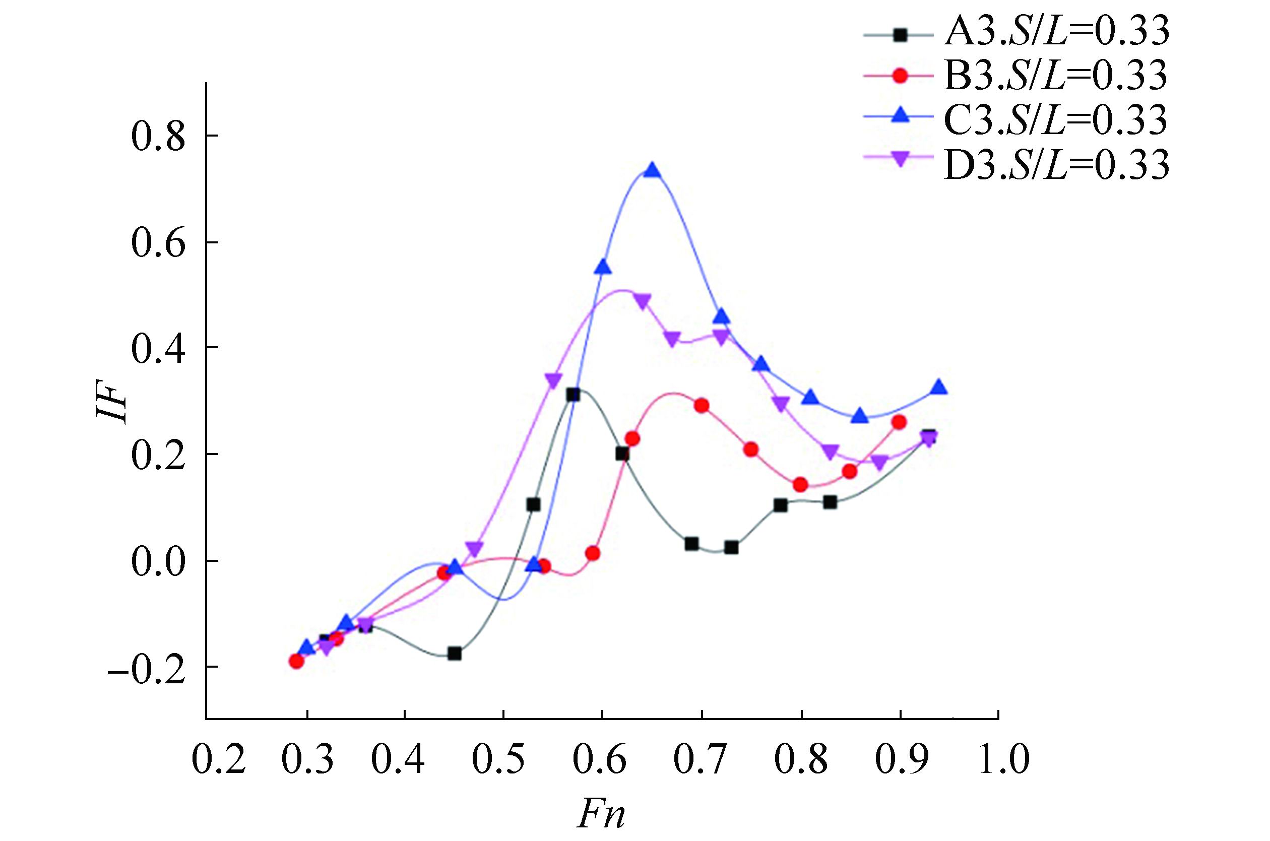
Focused on the optimum hull separation (S/L=0.33) and based on above resistance results, Fig. 9 presents the interference factor for each different asymmetric outrigger configuration. From this figure, we observed the interference characteristics that were previously stated in Fig. 8. However, when comparing the four hull separations, the outer outrigger position: asymmetric outboard showed excellent interference performance mainly at high speed with Froude number values greater than 0.6.
|
| Figure 9 Interference factor for hull configurations with S/L=0.33 |
This experimental study investigated the influence of different asymmetric outrigger configurations along with hull separations on a pentamaran Wigley-hull model. A noticeable change in resistance required significant changes in transverse distance values (hull separation) when wave interference occurred. In addition, there was no single configuration that consistently outperformed other configurations across the entire speed range. The optimum interference factor −0.2 appeared at a Froude number of 0.45 with the outer outrigger position: asymmetric outboard.
We believe that the effect of interference resistance occurring in a pentamaran ship should be examined further, particularly for different pentamaran configurations and asymmetric outrigger configurations. In addition, we hope that this study will be as useful as one of the data models for the numerical analysis of multihull hydrodynamic performances.
Acknowledgement:This work is sponsored by "Hibah PUPT RISTEK DIKTI 2016", Jakarta, Indonesia. Special honor to the late Dr. A. Jamaluddin, the senior researcher of Indonesia Hydrodynamic Laboratory, Surabaya, Indonesia. He has helped in collecting data during the test in IHL.
| Ackers BB, Michael TJ, Tredennick OW, Landen HC, Miller Ⅲ ER., Sodowsky JP, Hadler JB, 1997. An investigations of the resistance characteristics of powered trimaran outriggers configurations. SNAME Trans., 105, 349–373. |
| Broglia R, Jacob B, Zaghi S, Stern F, Olivieri A, 2014. Experimental investigation of interference effects for high-speed catamarans. Ocean Eng., 76, 75–85. DOI:10.1016/j.oceaneng.2013.12.003 |
| Doctors LJ, Scrace RJ, 2003. The optimisation of trimaran sidehull position for minimum resistance. The Seventh International Conference on Fast Sea Transportation, Naples, Italy, Keynote Lectures, 1–12. |
| Dudson E, Gee N, 2001. Optimization of the sea keeping and performance of a 40 knot pentamaran container vessel. Proc. 6th Int. Conf. on Fast Sea Transportation (FAST), RINA, Southampton, London. |
| Hafez K, El-Kot AR, 2011. Comparative analysis of the separation variation influence on the hydrodynamic performance of a high speed trimaran. J. Marine Sci. Appl., 10, 377–393. DOI:10.1007/s11804-011-1083-0 |
| Ikeda Y, Nakabayashi E, 2005. Concept design of a pentamaran type fast RORO ship. The Fifth International Forum on Aluminium Ships, Tokyo, Japan, 1, 35-42. https://www.jstage.jst.go.jp/article/jjasnaoe/1/0/1_0_35/_article |
| Muscat-Fenech CMDM, La Rosa AMG, 2014. Resistance analysis for trimaran. International Journal of Mechanical, Aerospace, Industrial, Mechatronic and Manufacturing Engineering, 8(1), 7-14. http://waset.org/publications/9997002 |
| Peng H, 2001. Numerical computation of multi-hull ship resistance and motion. Canada: Dalhousie University. |
| Peng H, Qiu W, Hsiung CC, 2004. Measuring wave resistance of high-speed multi-hull ship with a small towing tank. 27th American Towing Tank Conference, St. John's, Canada. 1-6, Paper No. 18. |
| Sahoo PK, Mynard T, Mikkelsen J, McGreer D, 2008. Numerical and experimental study of wave resistance for trimaran hull forms. The 6th International Conference on High-performance Marine Vehicles (HIPER '08), Naples, Italy, 117. |
| Souto-Iglesias A, Fernandez-Gutierrez D, Pierez-Rojas L, 2012. Experimental assessment of interference resistance for a series 60 catamaran in free and fixed trim-sinkage conditions. Ocean Eng. 53, 38. DOI:10.1016/j.oceaneng.2012.06.008 |
| Tarafder MdS, Khalil GMd, Nizam MdS, 2010. Numerical Prediction of wave-making resistance of tetramaran hull in unbounded water. Proc. The International Conference on Marine Technology (MARTEC), Dhaka, Bangladesh, 419–425. |
| Tarafder MdS, Ali MT Md., Nizam MdS, 2013. Numerical prediction of wave-making resistance of pentamaran in unbounded water using a surface panel method. Procedia Eng., 56, 287–296. DOI:10.1016/j.proeng.2013.03.120 |
| Tuck EO, Lazauskas L, 1998. Optimum spacing of a family of multihull. Ship Technology Research, 45, 180–195. |
| Yanuar, Gunawan, Talahatu MA, Indrawati RT, Jamaluddin A, 2013. Resistance analysis of unsymmetrical trimaran model with outboard sidehulls configuration. J. Marine Sci. Appl., 12(3), 293–297. DOI:10.1007/s11804-013-1193-y |
| Yanuar, Gunawan, Waskito KT, Jamaluddin A, 2015. Experimental study resistances of asymmetrical Pentamaran model with separation and staggered hull variation of inner outriggerss. International Journal of Fluid Mechanics Research, 42(1), 82–94. DOI:10.1615/InterJFluidMechRes.v42.i1.60 |
| Yanuar, Gunawan, Muhyi A, Jamaluddin A, 2016. Ship resistance of quadramaran with various hull position configurations. J. Marine Sci. Appl., 15, 28–32. DOI:10.1007/s11804-016-1340-3 |
| Yu W, Chen Xj, Wu Gh, Liu J, Hearn GE, 2015. A fast numerical method for trimaran wave resistance prediction. Ocean Eng., 107, 70–84. DOI:10.1016/j.oceaneng.2015.07.008 |
| Zaghi S, Broglia R, Di Mascio A, 2011. Analysis of the interference effects for high-speed catamarans by model tests and numerical simulations. Ocean Eng., 38, 2110–2122. DOI:10.1016/j.oceaneng.2011.09.037 |


