


1 Introduction
The turbine used for underwater vehicles is an axial-flow, short-blade, and partial-air admission impulse turbine engine. Some of its examples include the single-stage impulse turbine, multi-stage impulse turbine, and reentry impulse turbine. Speed loss for single-stage turbine is quite large, indicating that working gas still has higher kinetic energy after passing through the turbine, and that the intersection angle between air flow velocity and the axis of the turbine is still large, thus requiring the use of the kinetic energy of jet flow (Molland, 2011; Ahmadi et al., 2016; Huang et al., 2016).
The counter-rotating turbine system is mainly used in the aerospace area. The RB529 and the RB211 turbofan engine made by the Rolls-Royce Group in the UK adopted the counter-rotating turbine system. NASA carried out the energy efficient engine research program in 1970s, which considered the counter-rotating turbine system (Fang et al., 2005). The F119-PW-100 turbofan engine used in the F-22 fighter jets also uses a counter-rotating turbine technology.
In China, research on counter-rotating turbine technology is still at the initial stage. Cai analyzed the characteristics of the element stage of the counter-rotating turbine (Cai, 1992), whereas Yan expounded on the design principles of the liquid rocket engine turbo pump using the counter-rotating turbine (Yan, 1991). Moreover, other scholars have studied this system and investigated the flow field, the blade, and the cooling of the system (Quan et al., 2002; Yan, 2003).
This paper presents a method of adding a counter rotating second-stage turbine disk to the single-stage turbine, which achieves an unfixed proportional relative rotation with aerodynamic coupling; here, the first-stage turbine drives the propeller and the second-stage turbine drags the auxiliary system with planet deceleration mechanism (Raha et al., 2002; Hu et al., 2015; Zhao et al., 2015).
2 Counter-rotating turbineA counter-rotating turbine consists of a group of nozzles and two working turbines with the same structures. A diagram of the impulse counter-rotating turbine (Zhao, 2002;Akin and Sanz, 2014; Subbarao and Govardhan, 2014; Finney, 2011; Wang et al., 2011) is shown as Fig. 1.

|
| Figure 1 Cross-section view of the counter-rotating turbine engine |
Fig. 2 and Fig. 3 show the velocity triangles of working blade 1 and working blade 2, respectively (Baughman et al., 2004; Ji et al., 2008). In these figures, c1 denotes absolute velocity of gas at the inlet; w1 is relative velocity; c2 denotes absolute velocity of gas at the outlet; w2 is relative velocity; u is rotating speed; a is the direction of first-stage turbine shaft; u is the direction of rotating speed, α1and α2, β1and β2are the intersection angle between turbine disk plane and velocity, respectively. The aforementioned variables represent the parameters of working blade 1; the variables of working blade 1 are the same but with the superscript values (Johansson et al., 2015; Kanner, 2015).

|
| Figure 2 Velocity triangle of working blade 1 of the first-stage turbine |

|
| Figure 3 Velocity triangle of working blade 2 of the second-stage turbine |
Fig. 2 and Fig. 3 demonstrate the flowing situation of the fuel gas in the working blades, which contributes to the performance calculation of the counter-rotating turbine system.
3 Power balance of the counter-rotating turbine systemWhile utilizing the second-stage turbine to drag the auxiliary system, the auxiliary system power and the available kinetic energy of the second-stage turbine change at different working conditions. To ensure the normal operation of vehicles, the auxiliary system power should match the available kinetic energy, which means that the available kinetic energy of the second-stage turbine must be larger than the power of auxiliary system. Hence, the auxiliary system power and the available kinetic energy of the second-stage turbine must be respectively calculated.
The power of the generator to drive the electrical equipment changes little with the turbine power, so the generator power can approximate to constant as expressed by

|
(1) |
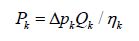
The power of the fuel pump, the oil pump, and the seawater pump can be computed using the equation
|
(2) |
where Δpk means the pressure rise of each pump, Qk denote the volume flow rate, and ηk is the efficiency of the pump.
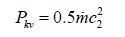
The second-stage energy can be obtained by calculating the outlet gas kinetic energy of the first-stage energy using
|
(3) |
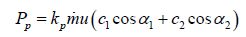
The power of the propeller is decided by the velocity triangle of working blade 1.
|
(4) |
The results of these computations are shown in Table 1.
| Speed/kn | Generator | Fuel pump | Oil pump | Seawater pump | Auxiliary power | Second-stage energy | Propeller | Improved efficiency/% |
| 30 | 7 | 1.3 | 1.22 | 12.4 | 21.9 | 70.49 | 64.8 | 25.20 |
| 50 | 7 | 8.5 | 3.4 | 29.3 | 48.2 | 163.78 | 300 | 13.80 |
| 70 | 7 | 33.89 | 6.67 | 54.7 | 102.36 | 233.93 | 823.3 | 11.06 |
Conventionally, the power of the auxiliary system at vehicles is dragged by the first-stage turbine, and the kinetic energy of working gas at the turbine outlet cannot be used. As shown in Table 1, the overall efficiency of the power system improves by approximately 10% at high working conditions when the second-stage turbine drags the auxiliary system, and reduces with the velocity of vehicles. Moreover, the auxiliary system power accounts for a higher proportion when vehicles are working at low velocity, at which the overall efficiency of power system would be much larger (Fu et al., 2012; Liu et al., 2013).
Hence, the second-stage turbine that drags the auxiliary system has a great help in increasing the efficiency of the power system, which in turn, improves vehicle speed and range correspondingly. This method provides theoretical foundation for future studies on the design of a turbine power system for use by underwater vehicles.
4 Counter-rotating turbine system modelThe schematic diagram of the underwater vehicle counter-rotating turbine power system is shown in Fig. 4, in which turbine engine is placed at the power tank of vehicles, and the output shaft of the first-stage drags the propeller through deceleration. The planet deceleration mechanism is deployed in the engine, after which the second-stage turbine drags the generator, fuel pump, seawater pump, lubricating oil pump, proportional relief valve at the seawater loop, proportional pressure-reducing valve at the seawater loop, proportional relief valve at the lubricating oil loop, and other servo mechanisms and motors (Luo et al., 2009).

|
| Figure 4 Schematic diagram of the counter-rotating turbine system’s structure |
In accordance with the command information from the onboard computer, the rotating speed controller would control the fixed rotating speed of the second-stage turbine at any given working condition (the rotating speed of the second-stage turbine at high working condition is taken as the theoretical rotating speed). Then, the control signal is outputted according to the theoretical rotating speed and real rotating speed from speed sensor in order to define the output flow of the lubricating oil, the pressure after seawater pump, and output flow (Ang et al., 2005; Jaw and Mattingly, 2009; Solingen and Wingerden, 2015; Saxena and Hote, 2016).
The mass flow rates of seawater, fuel, and lubricating oil change greatly at different working conditions, such as variable velocity and variable depth. Therefore, the controller sends the control command to change the inclined dish angle of the fuel pump, so that the mass flow rate of the fuel pump becomes equal to the required fuel flow at this working condition (Mccurry et al., 2009; Gao and Gao, 2016). Meanwhile, by adjusting the overflow rate of proportional relief valve at the lubricating loop, the lubricating oil rates at different components and friction pair match the required lubricating oil rate at this specific working condition. The proportional pressure-reducing valve at the seawater loop can change the pressure after seawater pump, and by adjusting the proportional relief valve, the pressure and flow rate at the seawater loop matches the required pressure and flow rate at this working condition. The output power of the second stage is balanced with the seawater loop and the lubricating loop (Xue et al., 2007).
5 Simulation experimentThe schematic diagram of the counter-rotating turbine system is shown in Fig. 5. As can be seen, working blade 1 drives the propeller, and working blade 2 drives the auxiliary system, including the lubricating oil loop, fuel loop, and seawater loop.

|
| Figure 5 Schematic diagram of the counter-rotating turbine system |
The counter-rotating turbine system employs the closed-loop control mechanism. The closed-loop control system structures for the rotating speed of working blade 1 and working blade 2 are presented in Fig. 6 and Fig. 7, respectively, where Gc (s) is the transfer function of the fuel pump displacement control mechanism, and the subscripts i and j of the transfer function Gij (s) refer to the input and output, respectively.

|
| Figure 6 Closed-loop control system structures for the rotating speed of working blade 1 |

|
| Figure 7 Closed-loop control system structures for the rotate speed of working blade 2 |
By modeling the turbine system, we can simulate the response characteristics of the auxiliary system under variable conditions of underwater vehicles equipped with the counter-rotating turbine system.
5.1 Lubricating oil loopFig. 8 and Fig. 9 indicate the variation curves of lubricating oil flow when vehicles are working at variable depth and velocity conditions, respectively. When t=0 s, the velocity of vehicle v is equal to 70 kn, and the sailing depth y is 30 m. The velocity of vehicles is reduced from 70 kn to 50 kn from 0 s to 10 s; moreover, the required lubricating oil for every component and friction pair is decreased, whereas the lubricating oil flow passing through proportional relief valve at lubricating oil loop increased. Vehicles descend from 30 m to 300 m from 10 s to 30 s, and the real velocity of vehicles is below 50 kn as a result of the increase of seawater back pressure. Moreover, the required lubricating oil for the power system would decrease, and thus, the flow passing through proportional relief valve at lubricating oil would increase slightly. Vehicles dive to 300 m at 30 s. The seawater back pressure remains unchanged from 30 s to 40 s, the velocity returns to 50 kn gradually, and the depth remains at 300 m. Therefore, the flow passing through proportional relief valve at the lubricating oil loop would decrease slightly.

|
| Figure 8 Required flow rate of lubricating oil of every component at working conditions with varying depths and velocities |

|
| Figure 9 Flow rate of the relief valve at lubricating oil loop at working conditions with varying depths and velocities |
The fuel pump sucks fuel from fuel storage tank, which is delivered to the combustion chamber after being pressurized by the variable displacement fuel pump. The fuel pump connects with the second-stage turbine with a constant rotating speed. The output flow of the fuel pump is changed by altering the inclined disk angle of the fuel pump with the servo mechanism. The variation curve of the output flow of the fuel pump at working conditions with varying velocities and depths are shown in Fig. 10. As can be seen, the velocity of vehicle v is equal to 70 kn at 0 s, and the sailing depth y is 30 m; the output flow of fuel pump is 1 L/s at this moment. The velocity of vehicle v decreases from 70 kn to 50 kn from 0 s to 10 s, and the output flow of the fuel pump also decreases to 0.5 L/s. The depth of vehicles dives from 30 m to 300 m from 10 s to 30 s. The seawater back pressure increases gradually with increasing depth, and the output flow of the fuel pump also begins to increase. Vehicles dive to 300 m at 30 s; therefore, the output flow of the fuel pump tends to be stable at 30 and 40 s.

|
| Figure 10 Variation curve of the output flow of fuel pump at the working condition with variable velocity and depth |
The variation curve of pressure at the outlet of the seawater proportional pressure-reducing valve is shown in Fig. 11. As can be seen, the velocity of vehicle v is equal to 70 kn when t=0 s; in addition, the maximum outlet pressure of the proportional pressure-reducing valve is 9.5 MPa. The velocity of vehicles decreases from 70 kn to 50 kn, the required cooling seawater decreases, and the outlet pressure of the proportional pressure-reducing valve also decreases to 2.1 MPa. At 10 s, vehicles begin to dive at the depth of 30 mm, reaching a depth of up to 300 m at 30 m. From 10 s to 30 s, the outlet pressure of the proportional pressure- reducing valve increases as a result of the increase of seawater back pressure. The outlet pressure would remain constant once vehicles reach the stable state at 300 m.

|
| Figure 11 Exit pressure of seawater proportional pressure- reducing valve at working conditions with variable velocities and depths |
The variation curve of the outlet flow of the seawater proportional relief valve is shown in Fig. 12. The velocity of vehicle v is 70 kn at 0 s, and the flow of the proportional relief valve is at the minimum point. The velocity of vehicles decreases from 70 kn to 50 kn from 0 s to 10 s, and the demand for seawater also decreases; hence, the flow of the proportional relief valve also rises. At 10 s, vehicles begin to dive at the depth of 30 mm, reaching a depth of up to 300 m at 30 m. From 10 s to 30 s, the outlet pressure of the proportional pressure-reducing valve increases as a result of the increased seawater back pressure. The outlet pressure would remain constant once vehicles reach the stable state at 300 m.

|
| Figure 12 Flow rate of seawater relief valve at working conditions with variable velocities and depths |
The following conclusions can be obtained with the theoretical analysis and simulation experiment.
1) Compared with the conventional single-stage turbine power system, the counter-rotating turbine power system can greatly improve the overall efficiency of power system. when the second-stage turbine drags the auxiliary system, it can improve the efficiency by approximately 10%-25%.
2) The experimental simulation of the counter-rotating turbine system is proposed. The results indicate that the requirements for an underwater vehicle running can be satisfied by the hydraulic transmission system properly.
3) The investigation of the counter-rotating turbine system can guide future research on the closed-loop control of a thermal power propulsion system employed in underwater weapons in China.
| Ahmadi BM, Carriveau R, Ting DS, 2016. A wind tunnel study on the aerodynamic interaction of vertical axis wind turbines in array configurations. Renewable Energy, 96(A), 904-913. DOI: 10.1016/j.renene.2016.05.060 |
| Akin MB, Sanz W, 2014. The influence of transition on CFD calculations of a two-stage counter-rotating turbine. Amer Soc Mechanical Engineers, Dusseldorf, 235-249. |
| Ang KH, Chong G, Li Y, 2005. PID control system analysis, design, and technology. IEEE Transactions on Control Systems Technology, 13(4), 559–576. DOI:10.1109/TCST.2005.847331 |
| Baughman JL, Orlando RJ, Moniz TO, 2004. Variable torque split aircraft gas turbine engine counter rotating low pressure turbines. U.S. Patent 6763652 B2. General Electric Company, Schenectady, 1-2 |
| Cai Ruixian, 1992. Basic analysis of counter-rotation turbines. Acta Aeronautica et Astronautica Sinica, 13(1), 57-63. (in Chinese) DOI: 10.3321/j.issn:1000-6893.1992.01.009 |
| Fang Xiangjun, Liu Siyong, Wang Ping, Zhang Weijun, 2005. Design and analysis of LP-vaneless contra-rotating turbine. Journal of Propulsion Technology, 26(3), 234-238. (in Chinese) DOI: 10.13675/j.cnki.tjjs.2005.03.010 |
| Finney AM, 2011. Gas turbine bleed energy recovery via counter rotating generator. U.S. Patent 8063501 B2. 1-3 |
| Fu C, Zou ZP, Liu HX, Li W, Zeng J, 2012. Aerodynamics design of two-stage counter-rotating turbine. Acta Aerodynamica Sinica, 30(3), 299–306. |
| Gao R, Gao Z, 2016. Pitch control for wind turbine systems using optimization, estimation and compensation. Renewable Energy, 91, 501–515. DOI:10.1016/j.renene.2016.01.057 |
| Hu H, Tian W, Ozbay A, 2015. An experimental investigation on the wake characteristics and aeromechanics of dual-rotor wind turbines. Chemical Engineering & Technology, 13(1), 304–312. DOI:10.1115/GT2015-43805 |
| Huang B, Usui Y, Takaki K, Kanemoto T, 2016. Optimization of blade setting angles of a counter-rotating type horizontal-axis tidal turbine using response surface methodology and experimental validation. International Journal of Energy Research, 40(5S1), 610–617. DOI:10.1002/er.3383 |
| Jaw LC, Mattingly JD, 2009. Aircraft engine controls: design, system analysis, and health monitoring. American Institute of Aeronautics and Astronautics, Reston, 113-124. |
| Ji Lucheng, Shao Weiwei, Wang Baocheng, 2008. Basic analysis of a counter-rotating turbine. Journal of Propulsion Technology, 29(1), 62–66. |
| Johansson M, Martensson J, Abrahamsson H, Povey T, Chana K, 2015. Aerothermal measurements and predictions of an intermediate turbine duct turbine vane. ASME Turbo Expo, Montreal, 204-215. DOI: 10.1115/GT2015-43449 |
| Kanner SAC, 2015. Design, analysis, hybrid testing and orientation control of a floating platform with counter-rotating vertical-axis wind turbines. PhD thesis, University of California at Berkeley, Berkeley, 2-10. |
| Liu Y, Zhuge W, Zheng X, Zhang Y, Zhang S, Zhang J, 2013. Study of mechanism of counter-rotating turbine increasing two-stage turbine system efficiency. International Journal of Fluid Machinery and Systems, 6(3), 160–169. DOI:10.5293/IJFMS.2013.6.4.189 |
| Luo Kai, Sun Junliang, Dang Jianjun, 2009. Modeling of underwater turbine engine propulsion system. Torpedo Technology, 17(2), 45-48. (in Chinese) DOI: 10.3969/j.issn.1673-1948.2009.02.011 |
| Mccurry CD, Mgaya R, Zein SS, 2009. Fuzzy decision-making in turbine engine controls. IEEE SOUTHEASTCON'09, Atlanta, the US, 3824-3826. |
| Molland AF, 2011. The maritime engineering reference book: a guide to ship design, construction and operation. Elsevier, Oxford, 730-783. |
| Quan Xiaobo, Li Wei, Ji Lucheng, Zhao Xiaolu, Xu Jianzhong, 2002. Primary design with cooling technology of the vanless counter-rotating turbine. Journal of Engineering Thermophysics, 23(4), 433-436. (in Chinese) DOI: 10.3321/j.issn:0253-231X.2002.04.011 |
| Raha KC, Adhav SS, Bhide NM, Yewale AD, Gupta GK, Karir JS, 2002. Thermal stability and shelf-life of high energy fuel for torpedoes. Defense Science Journal, 52(2), 165–171. DOI:10.14429/dsj.52.2161 |
| Saxena S, Hote YV, 2016. Decentralized PID load frequency control for perturbed multi-area power systems. International Journal of Electrical Power & Energy Systems, 81, 405-415. DOI: 10.1016/j.ijepes.2016.02.041 |
| Solingen E, Wingerden JW, 2015. Linear individual pitch control design for two‐bladed wind turbines. Wind Energy, 18(4), 677–697. DOI:10.1002/we.1720 |
| Subbarao R, Govardhan M, 2014. Effect of speed ratio on the performance and flow field of a counter rotating turbine. Energy Procedia, Amsterdam, 580-592. |
| Wang Xinping, Dang Jianjun, Zhao Zhicao, 2011. Research on closed-loop control of the step response. Applied Mechanics and Materials, 127(71), 71–76. DOI:10.4028/www.scientific.net/AMM.127.71 |
| Xue Ming, Luo Kai, Pang Liping, 2007. Research for speed changing character of turbine system based on pressure valve. Journal of Projectiles Rockets Missiles and Guidance, 27(1), 186–188. DOI:10.3969/j.issn.1673-9728.2007.01.057 |
| Yan Xiaona, 2003. The aerodynamic design method research of contra-rotating turbine. Master thesis, Northwestern Polytechnical University, Xi'an, 34-52. (in Chinese) |
| Yan Zichu, 1991. The development of turbopump technology for fluid rocket engines. Journal of Propulsion Technology(6), 23–30. |
| Zhao W, Wu B, Xu J, 2015. Aerodynamic design and analysis of a multistage vaneless counter-rotating turbine. Journal of Turbomachinery-Transactions of the ASME, 137(0610086). DOI: 10.1115/1.4028871 |
| Zhao Yingsheng, 2002. The principle of torpedo turbine engine. Northwestern Polytechinical University Press, Xi'an, 33. |