1 Introduction
The problem of Dynamical Positioning (DP) in automatic vessel control is one of the most significant problems in marine control system analysis and design.
Sørensen (2011) conducted an exhaustive survey of modern DP control systems designed using central theoretical and practical ideas. These systems are also presented in Fossen (1994, 2011), and Sørensen (2012) . Out of the existing publications devoted to DP control, the papers of Fossen and Strand (1999) and Loria et al. (2000) are highly significant. The approaches proposed in these works determine mathematical validation of the special structure of DP nonlinear control laws, using certain nonlinear asymptotic observers. In addition, they provide sufficient conditions for global asymptotic stability and validate the possibility of independent tuning for observers and state control laws using an analogy with a separation principle for LTI systems. This special structure allows the support of desirable system features, including an integral action and notching filter effect for external disturbances generated by sea waves. In this respect, certain ideas for providing the notch filtering effect are presented in Tannuri et al.(2003) and in the references therein.
However, despite the obvious advantages of the approaches mentioned, they all have one common drawback: the proposed DP control laws are not flexible enough, both in the sense of a separate design and in their lack of the separate use of the integral actors and dynamical filters. Instead, these items are incorporated into a comprehensive whole, which hampers their operational retun in a real time regime and overloads the system with additional useless dynamics.
In our opinion, the development of flexibility within the existing approaches is possible with respect to actual sea environmental conditions, and to achieve such flexibility the theory of multi-purpose control law synthesis could be used, as firstly presented in Veremey and Korchanov (1989) and transformed to its modern level in Veremey (2010, 2016). This approach is based on the special structure of control laws, and includes certain basic parts with several additional separate items that need to be adjusted for an actual sailing environment. Although the basic parts are invariant with the regime of motion, the additional elements can be switched on or off to provide the most superior dynamical behavior for the system. This paper therefore focuses on the crucial role of the so-called dynamical corrector, and aims to detemine desirable features for the closed loop connection with respect to counteracting external disturbances.
One of the most effective analytical and numerical tools used in designing all elements in a multi-purpose structure is that of the optimization approach. Its effectiveness is shown in the flexibility and convenience of modern optimization methods with respect to relevant, practical demands of control theory implementation. Veremey (2016) presents several aspects of the application of optimization ideology for marine autopilots design, and analysis of the features of this structure shows that an analogous ideology could also be implemented in DP control systems. However, practical optimization problems for the control design need to be solved in relation to the vast number of requirements, restrictions, and conditions involved in the closed-loop connection, which essentially hamper direct use of the necessary optimized conditions that could be traditionally applied to provide optimal synthesis of the control laws. This problem therefore requires special consideration.
This work is devoted to designing an optimal corrector for providing desirable dynamical behavior within the closed loop connection. The main goal of the corrector working in the economical regime of motion is to suppress the high-frequency part of the wave spectrum for the control signal driving actuators. If this goal is achieved, the dynamical corrector could then be considered to be a notch filter with respect to the wave disturbance of the control signal. In other words, the result of this type of filtering should be the slight reaction of the actuators to relatively high frequencies occurring in the sea wave process.
A certain solution for the analogous notch filtering problem for DP-control systems is presented in numerous works (Fossen, 2011; Loria et al., 2000; Sørensen, 2011; Hassani et al., 2012). The specific inconvenient feature of this approach is incorporation of integral actors and dynamical filters into a comprehensive whole on the basis of a nonlinear observer. However, as this is not fully relevant in the sense of flexibility, an alternative approach is proposed that is free from this inconvenience.
The central issues of this work are closely connected with the issues within previous papers written by the author, Veremey (2010) and Veremey (2013) . The first of these papers was devoted solely to a linear case for marine autopilot design, and the original expansion of nonlinear DP-control was realized. In the second publication, questions relating to the stability and integral features of the DP separate correction were discussed. The current paper contains new original results connected with optimal filtering tuning of a control law to provide an economical regime of motion.
This work is organized as follows. In Section 2, equations of the motion of DP vessels are presented, the special control law structureis introduced, and the problem of optimal filtering correction is posed. Attention is also devoted to issues of stability and astaticism, with the aim of determining an admissible set for optimization. In Section 3, main theoretical aspects of the filtering problem solution are discussed for the action of sea waves with a regular nature. Section 4 presents the computational procedure employed to realize filter tuning onboard, taking into account the realistic multiharmonic representation of sea waves. In Section 5, the proposed approach is illustrated using a practical example of filtering corrector synthesis, and finally, Section 6 concludes the paper by discussing overall results of the investigation.
2 Special structure of DP control lawTo consider the problems of DP automatic control, we accept the following widely used 3DOF nonlinear robot-like model of a DP vessel (Fossen, 1994; Hassani et al., 2012) :

|
(1) |
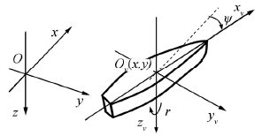
In the equations, $\mathbf{\nu }={{\left( u\ v\ r \right)}^{\text{T}}}$ is the generalized velocity vector defined in a vessel-fixed frame, ${{O}_{v}}{{x}_{v}}{{y}_{v}}{{z}_{v}}$; $\eta ={{\left( x\ y\ \psi \right)}^{\text{T}}}$ is the joint vector relative to an Earth-fixed frame,$Oxyz$ , that includes position $\left( x,\ y \right)$ parameters and the heading angle, $\psi $ (Fig. 1).
|
| Figure 1 Earth-fixed and DP vessel-fixed coordinate frames |
A displacement of x and a velocity of u determine the surge motion of the vessel; y and v determine the sway motion, and a pair of $\psi $ , r is referred to as the yaw motion.
The vector $\mathbf{\tau }\in {{E}^{3}}$ implies a control action generated by the propulsion system, and vector $\mathbf{d}\in {{R}^{3}}$ reflects an external disturbance of any nature. In addition, the matrices $\mathbf{M}={{\mathbf{M}}^{\text{T}}}$ and D with constant elements, are positive definite.
The orthogonal rotation matrix,

|
(2) |
determines the only nonlinearity of the system (1).
Notice that the system (1) only represents the DP-vessel and not the external disturbances, which is in contrast to the method used in existing approaches. Our representation appears to be suitable for providing notch-filtering features, as proposed below.
It is of note that measurements of vessel velocities are usually not available for the DP automatic system; thus, any control laws must be designed only on the basis of position and heading measurements. In this case, the central problem for DP system analytical design is to obtain a nonlinear dynamic control law of the form

|
(3) |
where $\mathbf{z}\in {{E}^{k}}$ is a state space vector of feedback coupling. If we accept the following design requirements for the closed loop system, (1) - (3), then the following needs to be addressed:
· This system must only have the equilibrium point $\mathbf{\nu }=0$, $\mathbf{\eta }={{\mathbf{\eta }}_{d}}$ , where ${{\mathbf{\eta }}_{d}}=\left( \begin{matrix} {{x}_{d}} & {{y}_{d}} & {{\psi }_{d}} \\ \end{matrix} \right)\in {{E}^{3}}$ is the desired constant position vector.
· This equilibrium must be Globally Asymptotically Stable (GAS).
· The controller (3) needs to provide an integral action with respect to Low Frequency (LF) components of the disturbance $\mathbf{d}(t)$ , and this is determined by the drift, current, and wind loads (external bias).
· The controller must also enable the system, (1) - (3), to produce a desirable reaction to wave generated components with a High Frequency (HF) of disturbance.
In common with Fossen and Strand (1999) , Fossen (2011) , and Loria et al.(2000) , let us introduce a structure for the control law (3) as follows,

|
(4) |

|
(5) |
where s is a Laplace variable.
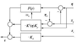
It is clear that the nonlinear asymptotic observer, (4), is constructed in accordance with the model, (1), but unlike in the above-mentioned research, the additional term $\mathbf{F}\text{(}s\text{)(}\mathbf{\eta }-{{\mathbf{z}}_{\eta }}\text{)}$ is added to Eq.(5) of the control former. This is tf-model of the LTI dynamical system, and it is known as a dynamical corrector within the transfer matrix $\mathbf{F}(s)$. It is a part of the control law that plays a crucial role in the following discussion.
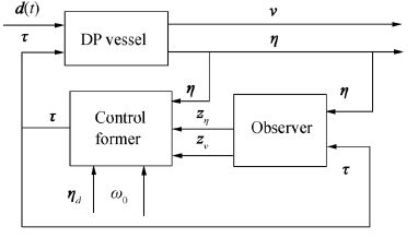
The structure of the proposed control law in (4) and (5) is illustrated in Fig. 2, where a full scheme of the closed loop connection is presented. An additional specification of the control former is presented in Fig. 3.
|
| Figure 2 Block-scheme of closed loop system |
|
| Figure 3 Block-scheme of control former |
Eq.(4) can be treated as a simplified version of the nonlinear asymptotic observer firstly proposed by Fossen and Strand (1999) . Here, ${{\mathbf{z}}_{\nu }}\in {{E}^{3}}$ and ${{\mathbf{z}}_{\eta }}\in {{E}^{3}}$ are estimations of the vectors $\mathbf{\nu }$ and $\mathbf{\eta }$, respectively. Simplification is determined by exclusion of the estimations of external bias and dynamical parameters of the vessel’s HF-motion.
Fossen and Strand (1999) proved that the matrices ${{\mathbf{K}}_{1}},\,{{\mathbf{K}}_{2}}$ must provide GAS and GES (globally exponentially stable) to the zero equilibrium position of the system as

|
(6) |
if $\mathbf{d}(t)\equiv 0$ . This system directly follows from that presented in (1) and (4), but it presents estimation dynamics with respect to the errors ${{\mathbf{\varepsilon }}_{\nu }}\text{(}t\text{)=}\mathbf{\nu }\text{(}t\text{)}-{{\mathbf{z}}_{v}}\text{(}t\text{)}$ and ${{\mathbf{\varepsilon }}_{\eta }}\text{(}t\text{)}=\mathbf{\eta }\text{(}t\text{)}-{{\mathbf{z}}_{\eta }}\text{(}t\text{)}$ of the observation. A sufficient condition of desirable stability is that of a diagonal structure and positive definiteness of matrices ${{\mathbf{K}}_{1}}$ and ${{\mathbf{K}}_{2}}$ . It is thus supposed that matrices with these properties are selected in the same way.
In accordance with the separation principal, a choice of the matrices ${{\mathbf{K}}_{d}}$ and ${{\mathbf{K}}_{p}}$ is connected with constructing the basic state-driving feedback control law of the PD-type form,

|
(7) |
which stabilizes the desirable equilibrium $\mathbf{\nu }=0$, $\mathbf{\eta }={{\mathbf{\eta }}_{d}}$ for the closed loop system (1) and (7), where $\mathbf{d}\text{(}t\text{)}\equiv 0$ . Loria et al.(2000) showed that the positive definiteness of the symmetrical matrices ${{\mathbf{K}}_{d}}$ and ${{\mathbf{K}}_{p}}$ guarantees this equilibrium position to be GAS. Let us suppose that these matrices are selected.
Thus, a solution for the synthesis problem of the control law, (4) and (5), can be determined by constructing the dynamical correction term $\mathbf{F}\text{(}s\text{)(}\mathbf{\eta }-{{\mathbf{z}}_{\eta }}\text{)}$ in Eq.(5). Determining this solution is the main subject of discussion in this paper. The corrector’s design problem is as follows. Firstly, it is necessary to find the transfer matrix,$\mathbf{F}(s)$, of the corrector so that the closed loop system, (1), (4), and (5), has the same GAS equilibrium position $\mathbf{\nu }=0$, $\mathbf{\eta }={{\mathbf{\eta }}_{d}}$, and provides the desirable integral and notch filter dynamical features of the system. From a formal point of view, this statement can be presented on a mathematical level using the following optimization problem,

|
(8) |
where $J(\mathbf{F})$ is a functional specifying the intensity of a control action. The admissible set, Ωc is determined here only by the condition, which provides GAS and the integral action of the controller. Here, $R{{H}_{\infty }}$ is a set of matrices that has proper fractionally rational components with Hurwitz denominators.
To explain the essence of the mentioned admissible set, Ωc, let us firstly consider a stability issue associated with the closed loop connection. Firstly, we introduce the matrices $\mathbf{\alpha },\,\mathbf{\beta },\mathbf{\gamma },\,\mathbf{\mu }$ of a corrector, such that $\mathbf{F}(s)\equiv \mathbf{\gamma }{{({{\mathbf{E}}_{l}}s-\mathbf{\alpha })}^{-1}}\mathbf{\beta }+\mathbf{\mu }$. This allows use to present the model in the state space form,

|
(9) |
where $\mathbf{p}\in {{E}^{l}}$ is the state space vector of the corrector, $\mathbf{\xi }\in {{E}^{3}}$ is its output vector, and ${{\mathbf{E}}_{l}}$ is the identity matrix. All the above-mentioned matrices with corresponding dimensions have constant components, and the matrix a is Hurwitz.
The following statement addresses the stability issue:
Theorem 1: If the LTI system (9) is asymptotically stable, then the equilibrium positionof $\mathbf{\nu }=0\text{, }\,\mathbf{\eta }={{\mathbf{\eta }}_{d}}$ of the closed loop system (1), (4), (5) is GAS.
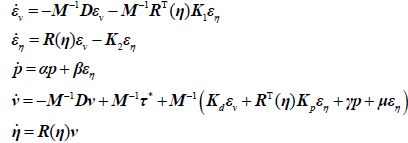
Proof: Firstly, we notice that the variables ${{\mathbf{z}}_{v}}\text{, }{{\mathbf{z}}_{\eta }}$ can be excluded from Eq.(5) of the control former by using observation errors. If we take into account (6), we can transform the equations of the controller, (4) and (5), to the equivalent form and consider the full system of equations, thereby presenting the closed loop connection with $\mathbf{d}\text{(}t\text{)}\equiv 0$ :
|
(10) |
It is thus possible to introduce new notations as ${{x}_{1}}={{\left( {{p}^{\text{T}}}{{v}^{\text{T}}}{{\left( \eta -{{\eta }_{d}} \right)}^{\text{T}}} \right)}^{\text{T}}},{{x}_{2}}={{\left( \varepsilon _{v}^{\text{T}}\varepsilon _{\eta }^{\text{T}} \right)}^{\text{T}}}$ and to rewrite Eq.(10) in the following form,

|
which has the same form as the cascaded equations obtained in Loria et al.(2000) . Simple calculations are then used to provide the subsequent reasoning, which is presented in detail in Veremey (2013) .
Theorem 1 allows us to claim that the separation principle can be expanded to the corrector (9) in some manner. It also means that the observer (4), the base controller (7), and the corrector (9) can be tuned independently of one another. Taking into account this independence, it is very convenient to use the dynamical corrector as the main item of the controller, (4) and (5), to provide the desirable features required by the feedback DP control system.
The main goal is to filter sea wave interference, but the flexibility of the corrector in the range of GAS also allows us to provide the desirable dynamics for the closed loop system relative to LF bias disturbances. Along with stability, one of the mandatory requirements of the controller is its integral behavior with respect to the above-mentioned actions.
To provide the integral feature of the controller, let us accept that the vessel is influenced by external disturbances with constant components. Due to the integral behavior, the closed loop system becomes astatic with respect to the position error vector,${{\mathbf{e}}_{\eta }}=\mathbf{\eta }-{{\mathbf{\eta }}_{d}}$ , i.e., this vector tends to zero as $t\to \infty $ for any external disturbance,$\mathbf{d}(t)\equiv {{\mathbf{d}}_{0}}$ , with constant components. Let us obtain a requirement for the transfer matrix $\mathbf{F}(s)$ of the dynamical corrector (9) that guarantees the above-mentioned property of a controller.
Theorem 2: If the following condition holds,

|
(11) |
and if a transfer matrix $\mathbf{F}(s)$ satisfies the equality,

|
(12) |
where ${{\psi }_{d}}$ is the equilibrium value of a heading angle,

|
then the system (1), (4), (5) is astatic with respect to the position error vectorfor ${{\mathbf{e}}_{\eta }}=\mathbf{\eta }-{{\mathbf{\eta }}_{d}}$ any ${{\mathbf{d}}_{0}}\in {{E}^{3}}$.
Proof: Firstly, let us suppose that equilibrium position of the closed loop system, (1), (4) and (5), exists for a certain external disturbance $\mathbf{d}(t)\equiv {{\mathbf{d}}_{0}}$, and let us consider the error Eq.(6) for the equilibrium position,

|
(13) |
Taking into account (11), it is possible to claim that the system (13) has a unique solution ${{\left( \begin{matrix} \mathbf{\varepsilon }_{\nu 0}^{\text{T}} & \mathbf{\varepsilon }_{\eta 0}^{\text{T}} \\ \end{matrix} \right)}^{\,\text{T}}}$.
Now, let us consider the equations of the controller, (4) and (5), for the mentioned equilibrium,

|
(14) |
It is very easy to obtain the requirement (12) for the matrix $\mathbf{F}\text{(}s\text{)}$ that directly follows from (14), which also guarantees the zero position error ${{\mathbf{e}}_{\eta }}=\mathbf{\eta }-{{\mathbf{\eta }}_{d}}$ of the system.
It is of note that the simplest way to realize the requirement (12) is by using a corrector with no dynamics, i.e.,$\mathbf{F}(s)\equiv {{\mathbf{K}}_{\Delta }}$ .
Let us point out that the proposed approach for providing integral behavior has another nature, and that this nature is other than that of the method considered in Loria et al.(2000) based on bias estimation. This simplifies the structure of the estimator and supports certain flexibility of the controller, as discussed below. Further details concerning the stability and integral features of the closed loop connection can be found in Veremey (2013) .
Summarizing the arguments presented above, it is possible to claim that the admissible set, Ωc, in (8) consists of matrices, F, with proper fractionally rational components that have Hurwitz denominators and satisfy (12).
3 Problem of optimal filtering correctionIn accordance with the optimization problem (8), the main purpose of the dynamical corrector, (9), discussed in this study is to support an economical regime of motion that provides a notch filtering effect for a given spectrum of sea waves. In addition, a dynamical corrector needs to maintain the integral property of the feedback connection, and must be asymptotically stable to guarantee GAS of the equilibrium point $\mathbf{\nu }=0$,$\mathbf{\eta }={{\mathbf{\eta }}_{d}}$ for the closed loop system, (1), (4), and (5).
In other words, the dynamical corrector working in an economical regime should suppress a certain high-frequency part of the wave spectrum for the control signal driving a rudder actuator. If this goal is achieved, the dynamical corrector could be considered to be a filter with respect to the wave disturbance of the control signal. Correspondingly, the dynamics of the closed loop system, (1), (4), and (5), reduce fuel consumption and prevent wear of actuator elements when moving under the influence of a sea wave.
As it is, the result of this type of filtering should be the slight reaction of actuators to relatively high frequencies of the sea wave process.
From a mathematical point of view, it is necessary to address the above-mentioned optimization problem (8). Given a controlled plant (1) and the control law (4) and (5), it is possible to find the transfer matrix,$\mathbf{F}(s)$, of the dynamical filter, so that the intensity of the control action is minimal with respect to other controllers from the admissible set, Ωc.
To concretely define the optimization problem, (8), let us introduce a concrete type of the functional J (F) to determine the intensity of action of the controller, (4) and (5). In this respect, let us firstly suppose (for simplicity) that the influence of sea waves is determined only by the dominate frequency,${{\omega }_{0}}$ , entering the wave’s spectrum.
In this case, the HF part of the external disturbance can be treated as the harmonic vector process,$\mathbf{d}\text{(}t\text{)}={{\mathbf{a}}_{d}}\text{sin}{{\omega }_{0}}t$ , with a vector,${{\mathbf{a}}_{d}}\in {{E}^{3}}$, of magnitude. For this case it is possible to define the intensity functional as follows,

|
(15) |
where ${{\mathbf{a}}_{\tau }}(\mathbf{F},{{\omega }_{0}},{{\mathbf{\eta }}_{a}})={{\left( \begin{matrix} {{a}_{\tau 1}} & {{a}_{\tau 2}} & {{a}_{\tau 3}} \\ \end{matrix} \right)}^{\text{T}}}\in {{E}^{3}}$ is the vector of the magnitude of the control action for a closed loop system, (1), (4) and (5), in relation to the mentioned disturbance. This vector corresponds to the time moment of the DP-process, when a heading angle has an initial given value of Ψ=Ψa, although it is possible to accept Ψa=Ψd.
To consider the filtering problem, (8), let us make some preliminary transformations, introducing the notation

|
(16) |
for the positioning error e . This allows us to rewrite the vessel Eq.(1) as follows,

|
(17) |
using the new state space vector ${{\left( \begin{matrix} {{\mathbf{\nu }}^{\text{T}}} & {{\mathbf{e}}^{\text{T}}} \\ \end{matrix} \right)}^{\text{T}}}$.
In accordance with (16), let us also introduce the auxiliary vector variable,${{\mathbf{z}}_{e}}$ , by the formulae

|
(18) |
It is evident that the following equalities hold,

|
(19) |
which allows us to rewrite observer Eq.(4) in the form

|
(20) |
It is very evident that the system, (20), can be treated as an asymptotic observer with respect to the vessel equations (17). In fact, the errors ${{\mathbf{\varepsilon }}_{\nu }}=\mathbf{\nu }-{{\mathbf{z}}_{\nu }}$ and ${{\mathbf{\varepsilon }}_{e}}=\mathbf{e}-{{\mathbf{z}}_{e}}$ in conformity with (17) and (20), satisfy the system

|
(21) |
which has an asymptotically stable zero equilibrium position, if $\mathbf{d}\text{(}t\text{)}\equiv 0$, equal to (6), i.e.,${{\mathbf{z}}_{\nu }}\to \mathbf{\nu },{{\mathbf{z}}_{e}}\to \mathbf{e}$ as $t\to \infty $. Therefore, the auxiliary variable,${{\mathbf{z}}_{e}}$, introduced by (18), is an estimation of the positioning error $\mathbf{e}=\mathbf{\eta }-{{\mathbf{\eta }}_{d}}$.
Let us note that the equations (21), (20), and (5) fully determine a control DP action for any instant of time. Taking into account (19), and the equalities $\mathbf{e}-{{\mathbf{z}}_{e}}={{\mathbf{\varepsilon }}_{e}},{{\mathbf{z}}_{\eta }}-{{\mathbf{\eta }}_{d}}={{\mathbf{z}}_{e}}$, it is easy to present these equations in the form

|
(22) |
The equations in (22) represent the operation of the dynamic system using the block-scheme shown in Fig. 4, where the first block realizes an operator,${{\mathbf{H}}_{\varepsilon }}$, with parameter $\mathbf{\eta }$ , which transforms the input, $\mathbf{d}$ into the output,${{\mathbf{\varepsilon }}_{e}}$, in accordance with the first two equations in (22). The second block is a LTI corrector with transfer matrix,$\mathbf{F}$ , and the third block produces the control signal, , in conformity with the last three equations of the system, (22). This block acts on the inputs,${{\mathbf{\varepsilon }}_{e}}$ and $\mathbf{\xi }$ , by the operator,$\mathbf{P}$ , depending on the parameter,$\mathbf{\eta }$.

|
| Figure 4 Block-scheme of control τ formation |
Because the closed loop system has unique, asymptotically stable equilibrium, the evident boundedness of the norm for the rotation matrix $\mathbf{R}\text{(}\mathbf{\eta }\text{)}=\mathbf{R}\text{(}\psi \text{)}$ holds. This allows us to treat $\mathbf{R}$ as the limited matrix function of the variable, t. Therefore, both the first and the third blocks are linear (but not time invariant) systems with limited, time-varying coefficients.
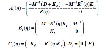
The following state space model represents the third block,
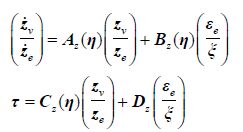
|
(23) |
where
|
In addition, the following statement determines a solution of the problem, (8), for the mentioned harmonic disturbance:
Theorem 3: If the block,${{\mathbf{P}}_{2}}(s,{{\mathbf{\eta }}_{a}})$, of the matrix

|
(24) |
satisfies the condition

|
(25) |
then the transfer matrix $\mathbf{F}={{\mathbf{F}}^{*}}\in {{\Omega }_{c}}$ of the corrector, (9), exists such that

|
(26) |
Proof: Let consider the value Ψ=Ψa of the heading angle mentioned above, correspondingly denoting $\mathbf{\eta }={{\mathbf{\eta }}_{a}}$, and form the tf-model with this vector for the system (23) as

|
(27) |
with the transfer matrix $\mathbf{P}(s,{{\mathbf{\eta }}_{a}})$ presented by (24).
In accordance with $\mathbf{\xi }=\mathbf{F}(s){{\mathbf{\varepsilon }}_{e}}$, taking into account (24) and (25), from (27) we obtain

|
(28) |
Finally, on the basis of (28), it is possible to conclude that for any asymptotically stable corrector with a transfer matrix, F, satisfying the condition,

|
(29) |
the equality,${{\mathbf{a}}_{\tau }}\text{(}{{\mathbf{F}}^{*}}\text{,}{{\omega }_{0}}\text{,}{{\mathbf{\eta }}_{a}}\text{)}=0$, holds for the vector of control magnitudes.
Next, let us prove existence of the transfer matrix $\mathbf{F}={{\mathbf{F}}^{*}}\in {{\Omega }_{c}}$ of the corrector, (9), satisfying the condition (28). Firstly, if we recall that with (29) it is necessary to provide the stability and integral action with respect to disturbances, it is thus necessary to find the transfer matrix

|
(30) |
$(i=\overline{1,3})$ of the dynamical filter

|
(31) |
such that the equalities

|
(32) |
hold, where ${{\mathbf{K}}_{\Delta i}}$ and $\mathbf{F}_{i}^{*}\text{(}{{\omega }_{0}},{{\mathbf{\eta }}_{a}}\text{)}$ are the ith rows of the matrices ${{\mathbf{K}}_{\Delta }}$ and ${{\mathbf{F}}^{*}}\text{(}{{\omega }_{0}},{{\mathbf{\eta }}_{a}}\text{)}$ corresponds to $(i=\overline{1,3})$. In addition, the common denominator of the fractions ${{f}_{ik}}(s)$ $(i,k=\overline{1,3})$ must be Hurwitz.
In accordance with the notations (30) and (32) for the fixed value ${{\psi }_{a}}$, it is possible to present the output,${{\xi }_{i}}$, of the filter (31) as an output of the LTI system, which has the tf-model

|
(33) |
with correspondent state space submissions

|
(34) |
Let us show that the equalities (32) can be satisfied by the transfer matrix (30) with the rows

|
(35) |
for the system (34), where ${{\mathbf{p}}_{i}}\in {{E}^{2}}$ is the ith state vector of the filter.
To begin with, let us select any Hurwitz matrices,${{\mathbf{\alpha }}_{i}}$ , with dimensions of 2×2$(i=\overline{1,3})$. Then, introducing the notations

|
(36) |
it is easy to rewrite the conditions (32) in the form

|
and, taking into account (35), we obtain

|
(37) |
Note that the matrix ${{\mathbf{E}}_{2}}\text{j}{{\omega }_{0}}-{{\mathbf{\alpha }}_{i}}$ is nonsingular, and denote

|
(38) |
After substitution to Eq.(37), we obtain

|
(39) |
Let us select any 1×2 vector-row ${{\mathbf{\gamma }}_{i}}$ , for example ${{\mathbf{\gamma }}_{i}}=\left( \begin{matrix} 0 & 1 \\ \end{matrix} \right)$. The relationships, (39), for every number,i , then form a system consisting of six equations with six unknown variables, which are the components of the 2×3 matrix,${{\mathbf{\beta }}_{i}}$. The unique solution of this system, if its matrix is nonsingular, is

|
(40) |
Finally, it is easy to find the 1×3 vector-row,${{\mathbf{\mu }}_{i}}$, from the first equation in (37) as

|
(41) |
As a result, all the matrices are obtained for Eq.(33), which allows us to finally construct the optimal filtering corrector, adjusted to the frequency ${{\omega }_{0}}$, of the form
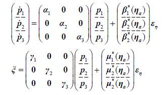
|
(42) |
Therefore, any corrector mentioned provides (32), and it is possible to accept it as a solution for problem (8) with the functional (15), i.e. as an optimal filter adjusted to the frequency ω0 and to the angle Ψa.
4 Filter tuning procedureIt is evident that applying the simplest variant of the problem considered above is suitable only for a situation where the sea waves are regular, when the formal disturbance representation is a harmonic oscillation with the known frequency, ω0. Nevertheless, such a representation is too simplified for the real conditions of a DP vessel’s motion. The situation can be made more complicated by using H2 or H∞ norms as J (F) (Bokova and Veremey, 1996; Veremey, 2011, 2012). Nevertheless, we propose here another way in which the physical reality is considered, and where it is necessary to force the controller to suppress not only the single frequency, but also the whole range of frequencies in accordance with the spectrum of an irregular sea wave.
To make the situation more realistic, let us suppose that the influence of sea waves is determined by the finite number of dominant frequencies,${{\omega }_{k}}\text{,}\,\,k=\overline{1\text{,}N}$, entering the wave’s spectrum. This assumption allows to treat an external disturbance as the multiharmonic vector process d (t) =Adsinωt, with the 3×N matrix Ad of magnitudes, and with the vector $\mathbf{\omega }={{\left( {{\omega }_{1}},\,{{\omega }_{2}}\text{,}...\text{,}{{\omega }_{N}} \right)}^{\text{T}}}$ of frequencies. For this case, it is quite suitable to change the definition of the intensity functional with respect to (15) as

|
(43) |
where ${{\mathbf{a}}_{\tau }}\text{(}\mathbf{F},\mathbf{\omega },{{\mathbf{\eta }}_{a}}\text{)}={{\left( \begin{matrix} {{A}_{\tau 1}} & {{A}_{\tau 2}} & {{A}_{\tau 3}} \\ \end{matrix} \right)}^{\text{T}}}\in {{E}^{3}}$ is the vector of control action magnitudes for the system, (1), (4) and (5), with the mentioned disturbance. This vector also corresponds to the time moment of the DP-process, when a heading angle has the initially given value Ψ=Ψa, and where, in particular, it is possible to accept Ψa=Ψd.
With respect to Theorem 3, let us present a statement that determines a solution for the problem (8) in relation to multiharmonic disturbance:
Theorem 4: If the condition (25) of Theorem 3 holds, and if the 2N ×2N matrices

|
(44) |
are nonsingular, where

|
(45) |
then the transfer matrix $\mathbf{F}={{\mathbf{F}}^{*}}\in {{\Omega }_{c}}$ of the corrector (9) exists, such that

|
(46) |
where ${{\mathbf{\alpha }}_{i}}$ are any Hurwitz 2N ×2N matrices, and ${{\mathbf{\gamma }}_{i}}$ are any 1×N vector-rows, for example

|
Proof: In contrast with Theorem 3, the filters (33) and (34) should be adjusted not for the only frequency ω0, but for all frequencies ${{\omega }_{k}},\,\,k=\overline{1,N}$. To provide such an adjustment, let us suppose that the state vectors of the filters (34) have dimensions, i.e., and

|
(47) |
Correspondingly, the conditions of adjustment of the ith filter (33) to the kth frequency, ωk, are as follows,

|
(48) |
where

|
(49) |
It is of note that the matrices ${{\mathbf{E}}_{2}}\text{j}{{\omega }_{k}}-{{\mathbf{\alpha }}_{i}}$ are nonsingular, and we introduce the notations (45) after substitution to Eq.(48), to obtain

|
(50) |
Let us select any Hurwitz $\rho \times \rho $ matrices ${{\mathbf{\alpha }}_{i}}$ and $1\times N$ any vector-rows ${{\mathbf{\gamma }}_{i}},\,\,i=\overline{1,3}$. The relationships, (50), for every number, i, form a system consisting of $2N\times 3$ equations with $2N\times 3$ variables, which are components of the matrix βi,

|
(51) |
where

|
The system (51) has a unique solution,

|
(52) |
which allows to determine matrices ${{\mathbf{\mu }}_{i}}$ from the first equation in (48) as

|
(53) |
As a result, the optimal filtering corrector (42) can be constructed using the formulae (52) and (53). In addition, it can be adjusted to given frequencies, belongs to the set ${{\Omega }_{c}}$, and satisfies (46).
Let us summarize the computational operations that need to be performed in real time onboard for optimal filter tuning. The set of initial data consists of the matrices $\mathbf{M},\,\mathbf{D},\,{{\mathbf{K}}_{1}},{{\mathbf{K}}_{2}},\,{{\mathbf{K}}_{d}},\,{{\mathbf{K}}_{p}}$, the values ${{\omega }_{1}},\,\text{ }{{\omega }_{2}}\text{, }...\text{, }{{\omega }_{N}}$ of the wave dominant frequencies, and the value Ψa of the angle for tuning.
It is important to stress that the filter tuning procedure can be easily implemented onboard in a real-time regime, and to do so the following steps need to be followed:
1) In the DP control system design stage, select the initial matrices, ${{\mathbf{K}}_{1}},{{\mathbf{K}}_{2}},\,{{\mathbf{K}}_{d}},\,{{\mathbf{K}}_{p}}$, based on certain desirable features of transient processes for the closed loop connection, (1), (4), and (5), accepting $\mathbf{F}\text{(}\operatorname{s}\text{)}\equiv 0$. Here, it is possible to use any optimization approach (Veremey, 2010).
2) Using the initial data, calculate matrix ${{\mathbf{K}}_{\Delta }}$(12) to provide the integral action of the controller. Next, it is necessary to select Hurwitz matrices, ${{\mathbf{\alpha }}_{i}}$, with dimensions of $2N\times 2N$ and any $1\times N$ vector-rows ${{\mathbf{\gamma }}_{i}}$,$i=\overline{1,3}$. The matrices $\mathbf{\alpha }_{ik}^{R}$ and $\mathbf{\alpha }_{ik}^{I}$ should then be computed using the formulae (45).
3) All of the following steps should be performed onboard. Firstly, before beginning the positioning maneuver, start a corresponding procedure to estimate the dominant frequencies ${{\omega }_{1}},\,\text{ }{{\omega }_{2}}\text{, }...\text{, }{{\omega }_{N}}$ of sea waves (Aranovskii et al., 2007; Belleter et al., 2013).
4) Secondly, for a given angle, Ψa, directly initiate the filter adjustment, calculating the matrices $\mathbf{F}_{i}^{*}\text{(}{{\omega }_{k}},{{\mathbf{\eta }}_{a}}\text{)}$ in accordance with (29), where is changed to ${{\omega }_{k}},k=\overline{1,N}$ . The matrices ${{\mathbf{R}}_{ik}}({{\mathbf{\eta }}_{a}})$ and ${{\mathbf{I}}_{ik}}({{\mathbf{\eta }}_{a}})$ (49) can then be obtained. Following this, via the expressions (52) and (53), it is possible to calculate the matrices $\mathbf{\beta }_{i}^{*}({{\mathbf{\eta }}_{a}})$ and $\mathbf{\mu }_{i}^{*}({{\mathbf{\eta }}_{a}})$ correspondingly with the optimal filter (42). It is of note that these calculations do not contain any iterative operations and do not induce any computational overheads.
5) After filter tuning, the onboard DP control system will provide all necessary standard operations to form a control signal (4), (5) for the thruster’s actuators.
Remark 1. If the results of tuning for an accepted value, ${{\psi }_{a}}$, of the heading angle are satisfactory for the whole DP transfer process in the sense of filtering quality, it is quite suitable to accept $\mathbf{P}(s,\mathbf{\eta })\equiv \mathbf{P}(s,{{\mathbf{\eta }}_{a}})$, and, consequently, obtain the matrix ${{\mathbf{F}}^{*}}(\mathbf{\eta })={{\mathbf{F}}^{*}}({{\mathbf{\eta }}_{a}})$ with constant complex components. Obviously, it is possible to treat any LTI corrector (9) with a transfer matrix of $\mathbf{F}={{\mathbf{F}}^{*}}({{\mathbf{\eta }}_{a}})$, as an approximate solution for the notch filtering problem. In particular, it may be possible to accept ${{\mathbf{\eta }}_{a}}={{\mathbf{\eta }}_{d}}$ when referring to the desired heading angle, Ψd.
Remark 2. If the results of the above-mentioned tuning are not satisfactory for the whole DP transfer process, it is possible to make a piecewise constant approximation $\left\{ {{\psi }_{a1}},{{\psi }_{a2}},\,\ldots \,\,,{{\psi }_{aN}} \right\}$ of the function Ψ (t), and provide filtering tuning for every value ${{\psi }_{ai}}\,\,\text{(}\operatorname{i}=\overline{1,\operatorname{N}}\text{)}$.
Remark 3. The procedure presented above provides an adjustment to the dominant sea wave frequencies ${{\omega }_{1}},\,\text{ }{{\omega }_{2}}\text{, }...\text{, }{{\omega }_{N}}$. To additionally take into account side frequencies, it is possible to vary eigenvalues of the matrices ${{\mathbf{\alpha }}_{i}},\,\,i=\overline{1,3}$.
Remark 4. The general way to obtain main frequencies of wave spectra are presented, for example, in Aranovskii et al.(2007) for a linear model of a vessel, and in Belleter et al.(2013) for a nonlinear model. The method in this study is based on using special estimators, providing asymptotic convergence to the mentioned values required.
Remark 5. As mentioned above, the proposed approach for providing integral behavior allows us to simplify a structure of the control law because of the absence of bias estimation. Nevertheless, if this reasoning is used onboard in relation to other purposes, it is also quite suitable to use the reasoning to provide the integral action. In this case, one can easily make corresponding changes and also use the proposed filter, excluding the equality (12).
5 Example of filter designLet us illustrate practical implementation of the mentioned tuning procedure using a practical example based on the DP control system for the vessel “Northern Clipper”, using the model (1) taken from Fossen and Strand (1999) . The length of this vessel is L=76.2 m and the mass is m=4.59×10⁶ kg; the correspondent matrices of the model (1) are accepted as follows,
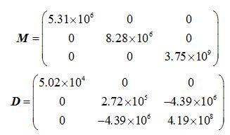
|
Let us also accept the matrices ${{\mathbf{K}}_{1}}$ and ${{\mathbf{K}}_{2}}$ of the observer (4), in accordance with the above-mentioned paper,

|
In addition, let the basic control law (7) be determined by the matrices

|
which provides the following eigenvalues for the closed loop system with small heading angles that accept $\mathbf{R}\text{(}\mathbf{\eta }\text{)}\approx {{\mathbf{E}}_{3\times 3}}$ as

|
Let then accept the desirable position vector as follows: ${{\mathbf{\eta }}_{d}}={{\left( {{x}_{d}}\ {{y}_{d}}\ {{\psi }_{d}} \right)}^{\text{T}}}$, ${{x}_{d}}=30\ \text{m}$, ${{\psi }_{d}}$ =45°, and determine the dominate frequencies of the wave’s spectrum:${{\omega }_{1}}=0.420,{{\omega }_{2}}=0.500,{{\omega }_{3}}=0.700$.
In accordance with the tuning procedure, firstly, let calculate the matrix (12)

|
to provide the astatic property with respect to a position error by the equality of $\mathbf{F}(0)={{\mathbf{K}}_{\Delta }}$ for the filter.
Next, let us select the Hurwitz matrices,${{\mathbf{\alpha }}_{i}}$, with dimensions of 6×6 in Frobenius form, that have initial given eigenvalues correspondingly of
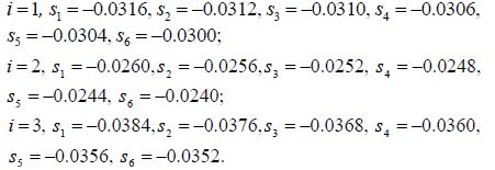
|
Furthermore, we accept
${{\mathbf{\gamma }}_{i}}={{\mathbf{\gamma }}_{0}}=\left( \begin{matrix} 0 & 0 & 0 & 0 & 0 & 1 \\ \end{matrix} \right),\,\,i=\overline{1,3}$. We then use simple calculations to obtain 6×6 matrices, $\mathbf{\alpha }_{ik}^{R}$ and $\mathbf{\alpha }_{ik}^{I}$, using the formulae (45).
We then calculate the matrices ${{\mathbf{F}}^{*}}\text{(}{{\omega }_{k}},{{\mathbf{\eta }}_{a}}\text{)}\,\,\text{(}i,k=\overline{1,3}\text{)}$ in accordance with (29) for the finished value ${{\psi }_{a}}={{\psi }_{d}}=45{}^\circ $ of the heading angle, to obtain for example

|
The matrices ${{\mathbf{R}}_{ik}}({{\mathbf{\eta }}_{a}})$ and ${{\mathbf{I}}_{ik}}({{\mathbf{\eta }}_{a}})$ (49) can then be calculated. Following this, via the expressions (52) and (53) we obtain the matrices, $\mathbf{\beta }_{i}^{*}({{\mathbf{\eta }}_{a}})$ and $\mathbf{\mu }_{i}^{*}({{\mathbf{\eta }}_{a}})$, correspondingly for the optimal filter (42).
As a result, we obtain the following equations of the optimal filter for the mentioned angle, ${{\psi }_{a}}$, as
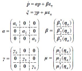
|
(54) |
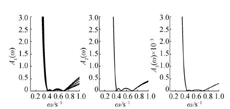
Results for other values of the heading angle are not essentially distinct. To validate this statement, we consider the family of frequency responses ${{A}_{i}}\text{(}\omega ,\psi \text{)}=\bar{\sigma }\left[ {{{\mathbf{\bar{P}}}}_{i}}\text{(j}\omega ,\psi \text{)} \right]$ (Fig. 5) forthe range $\psi \in \text{ }\!\![\!\!\text{ }0,\,{{360}^{\circ }}\text{ }\!\!]\!\!\text{ }$. Here ${{\mathbf{\bar{P}}}_{i}}$$(i=\overline{1,3})$ are the rows of the transfer matrix, $\mathbf{P}\text{(}\operatorname{s}\text{,}\psi \text{)}$(24). Analysis of the mentioned graphs allows us to accept $\mathbf{P}\text{(}s,\mathbf{\eta }\text{)}\equiv \mathbf{P}\text{(}s,{{\psi }_{a}}\text{),}$ and we then use the filter (54) as an approximate solution to the filtering problem.
|
| Figure 5 Graphs of frequency responses Ai (ω, Ψ),$\psi \in [0,\,\text{ }360{}^\circ ]$ |
Let us now consider the dynamical behaviour of the obtained closed loop connection, (1), (4), (5) and (54), to confirm that the desirable features have been acquired. Firstly, we introduce sea wave disturbance, $\mathbf{d}\text{(}\operatorname{t}\text{)}={{10}^{6}}{{\left( {{\operatorname{d}}_{\text{1}}}\text{(}\operatorname{t}\text{) }\ {{\operatorname{d}}_{\text{2}}}\text{(}\operatorname{t}\text{) }\ {{\operatorname{d}}_{\text{3}}}\text{(}\operatorname{t}\text{)} \right)}^{\text{T}}}$, which has stationary components ${{d}_{i}}(t)\,\,(i=\overline{1,3})$ with given power spectral densities of the form ${{S}_{di}}(s)={{S}_{1i}}(s){{S}_{1i}}(-s)$, where

|
$s=\text{j}\omega \text{,}\,\,\beta =0.455\text{,}\,\,\alpha /\beta =0.21$. Here, the dispersions ${{D}_{d1}}=10,{{D}_{d2}}=0.2,{{D}_{d3}}=300$, which can be treated as an approximate representation of sea wave action with an intensity of 5 on the Beaufort scale, are accepted.
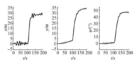
Fig. 6shows results of vessel motion simulation for the considered closed loop DP system, where it is possible to see the transient positioning processes $x(t),y(t)$ , and $\psi \text{(}\operatorname{t}\text{)}$, which consider the action of sea waves.
|
| Figure 6 Transient processes for closed loop system |
Correspondingly, Fig. 7 represents the control actions ${{\tau }_{1}}\text{(}\operatorname{t}\text{),}{{\tau }_{2}}\text{(}\operatorname{t}\text{)}$, and ${{\tau }_{3}}\text{(}\operatorname{t}\text{)}$, for the mentioned process.
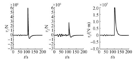
|
| Figure 7 Control actions for closed loop system |
To illustrate the effect of filtering, let us consider the same dynamical regime, but use the astatic corrector of the form

|
(55) |
instead of the filter (54). Naturally, the controller, (4), (5), and (55), holds an integral feature but loses a filtering feature. In this case, we obtain almost the same curves as in Fig. 6, which shows the positioning processes. Nevertheless, the control actions shown in Fig. 8-Fig. 9 differ essentially from those of the previous case, thereby confirming the effectiveness of filtering.
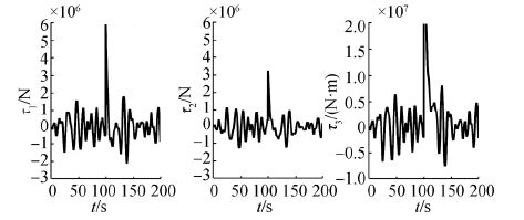
|
| Figure 8 Control actions for the corrector (55) |

|
| Figure 9 Control action τ3 for correctors (55) and (54) |
To further illustrate the notch filtering effect, let us consider a stabilization process presented by the graph of the control ${{\tau }_{3}}\text{(}\operatorname{t}\text{)}$ in Fig. 4 for the closed loop system. Prior to the 500th second, the controller (4), (5) works with the astatic corrector (55), but then the tuned corrector (54) is switched on to provide filtering features.
A comparison of both parts of the process illustrates the significant effectiveness of the proposed control law correction.
6 ConclusionsThe main goal of this paper is to expand the idea of a separate tuning for all units of the nonlinear DP control law. The presented approach can be treated as a certain modification of the notch-filtering solution (Fossen, 1994, Fossen, 2011; Sørensen, 2011, S2012), in that it represents state of the art DP control but supplements existing strategies using certain theoretical and practical conveniences.
From a theoretical point of view, the presented results provide a unified framework for the design of a flexible control action for DP systems. In particular, this approach develops a very important separation principle, which allows us to design a basic state control law, and the observer and corrector separately in a certain sense. This idea has not been fully implemented in previous approaches, where integral actors and dynamical filters were incorporated into the asymptotic observer. Although such a combination could be treated as a comprehensive whole, the separation principle could be applied only to the basic state control law and to the generalized observer turning, which hampered the operational retuning of the control law in a real time regime.
The proposed implementation of the dynamical corrector as a separate item opens the door to new ways of applying various formal optimization approaches, in particular H2 and H∞ optimization approaches, in the design an optimal transfer matrix F (s) for filtering initially given and other fixed items of the control law. Practically, the proposed scheme simplifies the control law due to the lack of need to restore both bias and wave disturbances: this activity is realized indirectly with the help of the corrector. Secondly, by using a control law with the structure of (4) and (5), flexibility of the scheme is granted by the corresponding tuning of the corrective term, $\mathbf{F}\text{(}s\text{)(}\mathbf{y}-{{\mathbf{z}}_{\eta }}\text{)}$, which can be independently performed in real time corresponding to the current regime of the vessel’s motion.
The results of the executed investigations presented above can be further developed to provide desirable performance indices for the DP control process on the basis of optimization approaches. In particular, this goal can be achieved using the full vessel+disturbance model, proposed in Fossen and Strand (1999) , Loria et al.(2000) . In addition, attention could also be given to questions of transport delay and robust features of DP control laws.
| Aranovskii SV, Bobtsov AA, Kremlin AS, Luk'yanova GV, 2007. A Robust algorithm for identification of the frequency of a sinusoidal signal. Journal of Computer and System Science International, 46(3), 371–376. DOI:10.1134/S1064230707030045 |
| Belleter DJ, Breu DA, Fossen TI, Nijmeijer H, 2013. A globally K-exponentially stable nonlinear observer for the wave encounter frequency. Proceedings of 9th IFAC Conference on Control Applications in Marine Systems (CAMS-2103), Osaka, 209–214. |
| Bokova YM, Veremey EI, 1996. Numerical aspects of spectral method of H∞-optimal synthesis. Journal of Automation and Information Sciences, 28(5), 1–12. |
| Fossen TI, 1994. Guidance and control of ocean vehicles. John Wiley & Sons Ltd., New York. |
| Fossen TI, 2011. Handbook of marine craft hydrodynamics and motion control. John Wiley & Sons Ltd., New York. |
| Fossen TI, Strand JP, 1999. Passive nonlinear observer design for ships using Lyapunov methods: experimental results with a supply vessel. Automatica, 35(1), 3–16. DOI:10.1016/S0005-1098(98)00121-6 |
| Hassani V, Sørensen AJ, Pascoal AM, Nguen TD, 2012. Multiply model adaptive dynamic positioning. 9th IFAC Conference on Maneuvering and Control of Marine Craft (MCMC-2012), Arenzano, 55-60. |
| Loria A, Fossen TI, Panteley E, 2000. A Separation principle for dynamic positioning of ships: theoretical and experimental results. IEEE Transactions of Control Systems Technology, 8(2), 332–343. DOI:10.1109/87.826804 |
| Sørensen AJ, 2011. A survey of dynamic positioning control systems. Annual Reviews in Control, 35, 23-136. |
| Sørensen AJ, 2012. Lecture notes on marine control systems. Technical report UK-12-76, Norwegian University of Science and Technology, Trondheim. |
| Tannuri EA, Bravin TT, Pesce CP, 2003. Dynamic positioning systems: comparison between wave filtering algorithms and their influence on performance. Proceedings of ASME 2003 22nd International Conference on Offshore Mechanics and Arctic Engineering (OMAE2003), Cancun, 1, 109–117. |
| Veremey EI, 2010. Synthesis of multiobjective control laws for ship motion. Gyroscopy and Navigation, 1(2), 119–125. DOI:10.1134/S2075108710020069 |
| Veremey EI, 2011. Algorithms for solving a class of problems of H∞-optimization of control systems. Journal of Computer and Systems Sciences International, 50(3), 403–412. DOI:10.1134/S1064230711010187 |
| Veremey EI, 2012. H∞-approach to wave disturbance filtering or marine autopilots. 9th IFAC Conference on Maneuvering and Control of Marine Craft (MCMC-2012), Arenzano, 410-415. |
| Veremey EI, 2013. Dynamical correction of positioning control laws. Proceedings of 9th IFAC Conference on Control Applications in Marine Systems (CAMS-2103), Osaka, 31-36. |
| Veremey EI, 2016. Optimization of filtering correctors for autopilot control laws with special structures. Optimal Control Applications and Methods, 37(2), 323–339. DOI:10.1002/oca.2170 |
| Veremey EI, Korchanov VM, 1989. Multiobjective stabilization of a certain class of dynamic systems. Automat and Remote Control, 49(9), 1210–1219. |


