


 , , , ,
2. Department of Naval Architecture, Ocean and Marine Engineering, University of Strathclyde, Glasgow, G4 0LZ, United Kingdom;
3. Hellenic Register of Shipping, Piraeus 18535, Greece
1 Introduction
The use of Liquefied Natural Gas (LNG) as fuel for the propulsion of commercial ships can lead to both a significant reduction in ship engine exhaust gas emissions (CO2, NOx, SOx, and PM) (IMO, 2009) and lower operational costs due to the substantially lower price of LNG (compared to diesel fuels). Thus, LNG fuel is expected to dominate the shipping industry as the most likely alternative fuel for many new-build and existing vessels. The idea of using LNG as ship fuel is not new as it has been used for many years on gas carriers with boilers (in the case of steam turbine propulsion) and in four-stroke diesel mechanical propulsion or diesel electric propulsion (Curt, 2004). In recent years, however, the LNG infrastructure has developed to the extent that a number of LNG-fueled ferries have been built (Word Ports Climate Initiative, http://www.lngbunkering.org/lng/vessels/ferries). For example, the “Viking Grace”—the first LNG-fueled passenger ship in the world—is operated by the Turku-Aland Islands (Finland) -Stockholm (Sweden) line carrying 2800 onboard passengers since 2013. Based on the obtained experience, LNG fuel has been established as a clean and reliable fuel for propulsion and auxiliary power generation. Apart from the obvious scenario of building new LNG-fueled ships, a significant number of currently operating vessels could be suitable for conversion to LNG fuel since retrofit solutions are becoming economically viable and worth considering (Aronietis et al., 2014). Hence, retrofitting existing ships for using LNG fuel is of great interest to the shipping industry from both economic and environmental perspectives.
In this study, we describe the conversion of an open-type Ro-Ro passenger ferry to the use of LNG fuel with respect to its safety systems. The investigation involves the analysis of all the necessary modifications and recommendations regarding the appropriate actions to be taken. In particular, we consider additional requirements for the ship safety systems to run on LNG and determine the necessary modifications. This study is based on national and international regulations for the operation of ships using LNG fuel (HRS rules http://www.hrs.gr, DNV GL rules https://www.dnvgl.com). We note that, to our knowledge, there are no existing studies investigating the retrofitting of an existing Ro-Ro passenger ferry with regard to vessel safety systems.
The modifications under evaluation cover all the ship's safety systems and are divided into four main categories, including: fire safety systems, ventilation systems, fire and gas detection safety measures, and ship evacuation procedures. Furthermore, we carry out a quantitative hazard identification study (HAZID) for an open-type ferry, based on input from an expert panel.
2 MethodologyAs stated above, in this study, we evaluated the technical feasibility of retrofitting a typical existing open-type Ro-Ro passenger ferry for its operation on LNG fuel. The particulars of the vessel are presented in Table 1. We note that the selection of the specific type of vessel is mainly based on the wide usage of similarly designed vessels operating on domestic coastal routes throughout the Greek territory, and especially those close to urban areas. Thus, the use of LNG as fuel for this particular type of vessel is of great interest and importance.
| Length/m | 102.5 |
| Breadth/m | 19.4 |
| Depth/m | 4.1 |
| Draft/m | 2.65 |
| Gross tonnage/t | 2110 |
| Speed/kn | 16 |
| Power output/kW | 4205 |
| Auxiliaries/kW | 415 |
| Passengers | 592 |
| Cars | 252 |
In this study, we focused our analysis on the following:
· Fire safety systems: We determined the modifications to the ship safety systems required for the storage and use of LNG as fuel, taking into consideration the additional requirements for the ship safety systems and the national and international regulations for the operation of ships with LNG fuel. In particular, we investigated the alterations required to fire insulation, fire pumps (number and capacity), fire line, water spray systems (sprinkler/drencher), and fixed/portable fire extinguishing systems (CO2).
· Ventilation system: We examined the topology of the existing system (air inlets/outlets), the capacity of the installed fans, and the capacity and location of additional fans required for the LNG fuel line.
· Fire and gas detection safety measures: We analyzed the advisability of adding an appropriate gas detection system and recommend a system type, sensor topology, and an appropriate interface to the ship's LNG fuel supply automation system.
· Evacuation plan: We reconsidered the number and topology of lifesaving appliances (i.e., number of life jackets, number and location of life rafts) and the evacuation procedures, taking into account the potential for gas leakage or fire at the LNG tanks.
· HAZID: We identified the main hazards and evaluated the severity and probability of each hazard with the participation of local maritime experts and research scientists.
2.1 Modification of fire safety systemsFollowing a number of onboard fire casualties, fire safety regulations for ships have been considerably improved. The increased need for fire safety standards onboard ships was the basis for the development of the current rules and regulations (Regulation 2, 2.1 SOLAS (1974) as amended). According to a previous study on the LNG fuel feeding system of this particular ship, two storage tanks are necessary (Theotokatos et al., 2015). The required LNG tanks are located on an appropriate superstructure on top of the platform deck, as shown in Fig. 1.

|
| Figure 1 Insulation at platform deck and at the superstructure boundaries where the LNG tanks are located |
In the following sections, we examine the fire safety systems of the specific ship to determine the feasibility of using LNG fuel, with respect to fire safety and the potential need for modifications. Specifically, in this case study, we analyzed the following: fire insulation, fire pumps (number and capacity), fire line, water spray systems, and fixed/portable fire extinguishing systems.
2.1.1 Fire insulationAccording to SOLAS regulations, fire divisions are classified with respect to fire insulation into three categories: “A”, “B, ” and “C” Class Divisions (Regulations 2, 3, 4, 10 SOLAS, 1974). Generally speaking, ships are divided into main vertical zones, which are those sections into which the hull, superstructure, and deckhouses are divided in “A” class divisions, the mean length and width of which on any deck does not typically exceed 40 m (Regulation 3, 32 of SOLAS (1974) ).
Most of the fire insulation used on the study vessel is of Class A-60 standard (see Fig. 2). Specifically, the floor of the accommodation deck and certain areas of the sun deck are shielded with Class A-15 insulation. The area of the emergency generator and the rest of the accommodation spaces are shielded with Class A-60 insulation. The sides of the ship's accommodation spaces from the main deck to the ceiling are shielded with Class A-60 insulation, while the windows in the accommodation deck are of Class A-0.

|
| Figure 2 Side view of the ship's existing fire insulation |
A number of modifications are necessary with respect to fire insulation in order for the vessel to comply with the additional requirements associated with LNG fuel. In particular, the following modifications should be considered:
· The docking station and superstructure where the LNG tanks are located should be shielded with Class A-60 insulation (the boundaries surrounding the LNG tanks are already shielded with class A-60 insulation, as shown at Fig. 1).
· The windows of the accommodation space facing the LNG tanks should be removed and replaced with appropriate Class A-60 standard insulation sheet.
· The bridge windows facing the LNG tanks should be replaced by windows of Class A-0 standard.
· The sides of stairways facing LNG tanks on the accommodation deck should be shielded with Class A-60 insulation.
2.1.2 Fixed fire extinguishing systemsAccording to Hellenic Register of Shipping (HRS) rules concerning fixed fire extinguishing types (Mizithras et al., 2015), every ship shall be equipped with sufficient means to suppress and swiftly extinguish a fire in the space of origin. Usually, the most common means of fire extinguishing is the main fire water supply system, consisting of hydrants and hoses. In addition, various fixed fire extinguishing systems can be installed on the ship for this purpose, to limit potential fire growth in protected spaces. Also, fixed fire extinguishing appliances can be used, which are usually one of the following types:
· Fixed gas fire extinguishing system
· Fixed expansion foam fire extinguishing system
· Fixed pressure water spraying fire extinguishing system
The ship is equipped with an appropriate fire sprinkler/drencher system according to Resolution A.123 (V) of the IMO (2012) and an appropriate CO2 system according to Chapter 2-II, Part A, R.5.1 of Council Directive 98/18/EC (1998) . The main characteristics of each system are presented below. We note that only the key aspects of each system are presented since there is no need to re-evaluate those already approved by the class and flag authorities.
The sprinkler system mainly consists of a pump with the nominal characteristics of 90 m3/h capacity and a 5 m head (the required capacity is 84 m3/h) and a sprinkler tank with a volume of 2 800 L. The sprinkler tank together with the sprinkler pump are located beside the aft-engine room. There are two sprinkler stations onboard, and their specifications are presented in Table 2.
| Sprinkler station | Deck | Area/m2 | Head/m |
| 1 | Accommodation deck | 1 012.26 | 120 |
| 2 | Wheel house deck, Sun deck | 169 | 21 |
The drencher system consists of three drencher pumps with the nominal characteristics of 140 m3/h capacity and a 30 m head, while the required capacity for the two largest drencher zones onboard is 269.5 m3/h. The drencher pumps are located in the aft-engine room. There are four main drencher zones onboard, and their specifications are presented in Table 3.
| Drencher zone | Area/m2 | Deck | |
| Height<2 m | Height>2 m | ||
| Zone 1 | 346.5 | - | Lower |
| Zone 2 | 346.5 | - | Lower |
| Zone 3 (A) | 213.6 | - | Main |
| Zone 3 (B) | 163.4 | 185.436 | Platform |
| Total zone 3 | 377 | 184.436 | |
| Zone 4 (A) | 213.6 | - | Main |
| Zone 4 (B) | 163.4 | 185.436 | Platform |
| Total zone 4 | 377 | 184.436 | |
The ship's fixed fire extinguishing system consists of five main CO2 cylinders located in the CO2 room at the fore side of the platform deck next to the stores room. The necessary CO2 capacity is directly proportional to the volume of each engine room, as per Chapter 2-II, Part A, R.5.2 of Council Directive 98/18/EC (1998) . For a total engine room volume of 288 m3, the required quantity of CO2 is calculated to be 206 kg. Therefore, a quantity of five 45 kg CO2 cylinders installed in each engine room is considered to be sufficient.
Taking into consideration the additional existing rules concerning the use of LNG fuel (HRS rules, Mizithras et al. 2015; GL Guidelines for the use of gas as fuel for ships, GL, 2010), we can conclude that the existing fixed fire extinguishing systems of the ship (i.e., sprinkler/drencher and CO2 systems) are sufficient. This is because both engine rooms of the ship are considered to be inherently safe (all gas fuel piping is of double-wall type) and there is no bunkering station onboard. As such, no alteration is necessary in the specific systems. We note, however, that a fixed water spray line for the LNG fuel tanks must be installed, as presented in the next section.
Water spray system for gas storage tanks
In this specific case, the required water spray system for cooling and fire prevention of the exposed parts of the gas storage tanks is incorporated into cassette-type LNG tanks. The required potential modifications with respect to the ship's fire pumps (i.e., number/capacity) should be determined in order to provide additional water supply, along with the necessary modifications to the ship's fire line.
According to the international safety rules imposed by R4 of Council Directive 98/18/EC (1998) , every ship shall be provided with appropriate fire pumps, fire mains, hydrants, hoses, and nozzles. Ships certified to carry more than 500 passengers, as in this ship's case, should have at least three fire pumps, one of which may be a main engine-driven pump.
Although there is no additional requirements concerning the number of fire pumps when using LNG fuel, appropriate calculations are necessary to verify that the capacity of the existing fire pumps is sufficient to deliver the additional supply to the water spraying system required for the LNG tanks. The ship already has four GS/Fire pumps installed (two in each engine room), and the nominal characteristics of each pump are a 37.5 m3/h capacity and a 40 m head.
First, we calculated the appropriate dimensions of the bilge line (internal diameter of main line and branch suction lines) to determine the minimum required bilge pump capacity. Then, we obtained the required fixed fire extinguishing capacity, QFFE, since it is proportional to the particular figures. Thus, we can determine if the capacity of the fire pumps already fitted onboard, Qinstalled, is sufficient to cover both systems (fixed fire extinguishing, QFFE, and LNG water spraying, QLNG_WS, i.e., Qinstalled≥QFFE+QLNG_WS).
According R21 of Council Directive 98/18/EC (1998) and HRS rules, Part 5, Chapter 9, 5.2 of the HRS (2015) , the internal diameters of the main bilge line and the branch bilge suction are calculated as being 101.5 mm and 56.3 mm, respectively. As a result, we derived the following:
· All the internal diameters of the main bilge lines should be at minimum 102 mm.
· All the internal diameters of the branch bilge suctions should be at minimum 57 mm.
These specification take into account that the total number of passengers of the ship is more than 500 and that the number of bilge pumps is at least three, according R21 of Council Directive 98/18/EC (1998) .
The minimum bilge pump capacity is calculated to be 59.23 m3/h according to HRS rules (HRS (2015) , Part 5, Chapter 9, 6.3).
We note that the ship has four bilge pumps installed, two located in each engine room, with the nominal characteristics of 70 m3/h capacity and a 30 m head.
Next, we calculated the maximum capacity of the fire pumps installed on the ship in order to determine the potential alterations required to the existing pumping system. The diameter of the ship fire line must be sufficient to effectively distribute the maximum required discharge from the fire pumps. As per regulations, each of the required fire pumps (other than any emergency pump required) shall have a capacity not less than 80% of the total required capacity divided by the minimum number of required fire pumps, but in any case not less than 25 m3/h, according to Chapter II-2, R4, 2 of Council Directive 98/18/EC (1998) .
The calculated minimum capacity for each pump according to the above rules is 29.61 m3/h, which is higher than that required for this particular ship type. We note that, according to the corresponding regulations for the specific ship type, a minimum of three fire pumps are required. In this particular ship, however, four fire pumps are already installed. The calculated capacity both for the bilge and fire pumps are presented in Table 4. We note that the calculated capacity of the fire pump is significantly lower than the installed fire pumping capacity.
| m3/h | |||
| Pump | Installed | Calculated | Difference |
| Fire pump | 37.5 | 29.61 | ~ 8 |
| Bilge pump | 70 | 59.23 | ~ 10 |
As mentioned above, the LNG water spray system should have an application rate of 10 L/min/m2 for horizontal projected surfaces, and the total surface of the area occupied by the two LNG tanks is equal to 59.5 m2. Thus, we calculated the additional flow rate necessary to cover the requirements for cooling the LNG tanks in an emergency situation to be 35.7 m3/h.
This specific figure is comparable to the minimum required capacity for each of the fire pumps onboard. Furthermore, the total pumping capacity required to fulfill both requirements (i.e., LNG water spray system, QLNG_WS, plus the minimum fixed fire extinguishing capacity for this particular ship type, QFFE) is equal to 29.61+35.7=65.32 m3/h, which is almost twice the capacity of each of the fire pumps.
As noted above, the ship is equipped with an additional fire pump, therefore, one possible solution is to dedicate this pump to the LNG water spray system. Thus, there would be three fire pumps to comply with the class requirement and one pump dedicated to the LNG water spray system. However, in order for this scenario to be feasible, the total hydraulic loss (taking into account the existing fire line and also the LNG water spray system line) should be less than 40 m (head of each fire pump).In the following section, we verify this capability.
Calculation of hydraulic loss for the existing fire line
We calculated the hydraulic loss for the existing fire line in order to determine if the necessary supply rate can be provided by a single fire pump. Note that the path for each branch of the fire line (for the horizontal hydraulic loss calculations) is considered to be the longest one on each deck (a typical path is presented in Fig. 3).

|
| Figure 3 Lower deck: Path line of the fire system (magenta line) |
The hydraulic loss, HLoss in meters, of each of the line braches is calculated by the following equation, which considers the friction and fitting (elbows and valves) losses:

|
(1) |
where λ is friction factor, Lp is the length of the fire line branch, din is the inner diameter of the pipe, ζ is the additional resistance of the fittings along the considered branch, W is the velocity of the fluid, and g=9.81 m/s2.
The friction factor, λ, can be easily obtained from a Moody chart, as a function of the Reynolds number, Re, and the relative roughness, ε/din, of the pipe for laminar or turbulent flow. For the surface roughness ε of the piping material, we use a representative value of 0.15 for the roughness of galvanized iron.
The head loss of the fire line branches on the lower deck, main deck, platform deck, accommodation and sun decks are presented in Table 5, together with the total hydraulic loss, which is equal to 20.56 m.
| Location | dout/mm | s/mm | din/mm | ε/din | Re×105 | λ | Lp/m | ζ | W/ (m·s−1) | HLoss/m |
| Lower deck | 88.9 | 4.5 | 80.9 | 0.0019 | 1.2 | 0.025 | 20.3 | 12.3 | 2.08 | 3.72 |
| Main deck | 76.1 | 3.6 | 68.9 | 0.0022 | 1.36 | 0.0255 | 4.06 | 3 | 2.77 | 1.74 |
| Platform deck | 76.1 | 3.6 | 68.9 | 0.0022 | 1.36 | 0.0255 | 48.14 | 5.1 | 2.77 | 8.8 |
| Accommodation deck | 53.1 | 0.0033 | 1.5 | 0.026 | 5.22 | 3.3 | 3.98 | 4.66 | ||
| Sun deck | 53.1 | 0.0028 | 1.55 | 0.026 | 1.74 | 1.2 | 3.98 | 1.64 | ||
| Total | 20.56 |
The elevation corresponding to the length of the vertical piping is equal to 13.4 m. Furthermore, the minimum water jet height at the last nozzle (on the sun deck) is considered to be 2.1 m (requirement imposed by Chapter II, R4 of Council Directive 98/18/EC, 1998). Thus, the minimum head increase of each pump is equal to 36.06 m, which is less than 40 m (head of each pump installed on board).
Calculation of hydraulic loss for the LNG water spray line
To calculate the hydraulic loss for the water spray system due to the LNG implementation, we assumed the path line for the water spray system to be identical to the fire main line up to the platform deck, where the line is connected to the LNG tanks' water spraying system (as shown in Fig. 4). The corresponding head loss for the water spray line for the platform deck is presented in Table 6.

|
| Figure 4 Platform deck: Path line of the water spray system to the LNG tanks (red line) |
| Location | dout/mm | s/mm | din/mm | ε/din | Re×105 | λ | Lp/m | ζ | W/ (m·s−1) | HLoss/m |
| Platform deck | 76.1 | 3.6 | 68.9 | 0.0022 | 1.36 | 0.0255 | 19.14 | 3.0 | 2.77 | 3.88 |
The total hydraulic loss for this particular line is the sum of the losses on the lower deck, the main deck (decks underneath, as listed in Table 5), and the loss calculated in Table 6. Thus, the total head loss is equal to 9.34 m.
The elevation corresponding to the length of the vertical piping is 14.5 m. Thus, the minimum head increase of the pump dedicated to the LNG water spraying line should be equal to 23.84 m, which is less than 40 m (head of each pump installed onboard). As a result, the head of one fire pump is considered to be sufficient.
As can been seen from the above calculations, the proposed alterations to the vessel fire line are feasible. Note that a connection to the ship fire line through a screw-down non-return valve should be provided in order to comply with the additional requirements for a fixed fire extinguishing system, when using LNG fuel.
2.1.3 Portable fire extinguishersApart from the installed fixed fire extinguishing system, the ship shall be provided with portable fire extinguishers, as per Chapter 2-II, Part A, R.6 5.1-5.6 of Council Directive 98/18/EC (1998) . According to GL Guidelines for the use of LNG fuel and the HRS rules concerning preventive measures and fire extinction by Mizithras et al.(2015) , one portable dry powder fire extinguisher of at least 5 kg capacity should be located near the bunkering station. We note that the above requirement is the only additional requirement concerning portable fire extinguishers when using LNG fuel.
According to the ship Fire Control Plan, there are 57 portable fire extinguishers onboard, described as follows:
· 20 air-foam fire extinguishers of 10 L capacity
· 31 dry powder fire extinguishers of 6 kg capacity and 2 dry powder fire extinguishers of 12 kg capacity
· 4 CO2 fire extinguishers
The above fire extinguishers are located on the ship decks, as shown in Tables 7 (a) and 7 (b).
| Extinguisher type | After engine room | Fore engine room | Machinery spaces | Garage (693 m2) |
| Dry powder fire extinguisher of 12 kg | 1 | 1 | - | - |
| Dry powder fire extinguisher of 6 kg | 1 | 1 | 2 | - |
| Air-foam fire extinguisher | 1 | 1 | - | 4 |
| Extinguisher type | Main deck (Deck 2) | Platform deck (Deck 3) | Lounge deck (Deck 4) | Sun deck (Deck 5) | Wheel house deck (Deck 6) |
| CO2 | - | - | - | 1 | 1 |
| Dry powder fire extinguisher of 6 kg | 16 | 2 | 7 | 2 | - |
| Air-foam fire extinguisher | 8 (10 L) | 4 | - | - | - |
There is no available bunkering station onboard the ship but there is a docking station located on top of the superstructure (since the two LNG tanks are cassette-type). Therefore, two additional dry powder extinguishers should be added to this area. Specifically, two dry powder fire extinguishers of 6 kg should be placed near the docking station as an additional safety measure, as shown in Fig. 5.

|
| Figure 5 Superstructure on top of which the two cassette-type LNG tanks are to be located |
In this section, we examine the ship's existing ventilation system to determine the need for any potential modifications to comply with the additional rules when LNG is used as fuel. The basic HRS requirements for ship ventilation systems are found in the technical report of Mizithras et al.(2015) , in the section concerning ventilation system provisions. Taking into consideration the additional requirements for using LNG fuel, the potential modifications must be determined and appropriate action be proposed accordingly. Potential modifications/ alterations mainly address the system topology (i.e., air inlets/outlets), the capacity of the existing fans to supply air to the engine rooms, and the installation of additional fans to preserve air exchange inside the fuel-gas piping systems.
We can safely assume that the existing ship ventilation system complies with its class/flag requirements. Furthermore, when running on LNG, the adequacy of the existing ventilation system in providing the required air change rate in the two engine rooms must be determined.
Air change rate calculation in machinery spaces:
The following specifications for the machinery spaces are those of the ship's ventilation plan:
Machinery space “A”:
· The capacity of the ventilation system of the machinery space is 29 000 m3/h
· The required air supply for the main engines is 12384m3/h
· The required air supply for the generators is 1 104 m3/h
· The remaining air supply capacity in the machinery space is equal to 15 512 m3/h.
For a machinery space volume equal to 286.32 m3, the air change rate is calculated as being equal to 54.18 air changes/hour.
Machinery space “B”:
· The capacity of the ventilation system of the machinery space is 29 000 m3/h
· The required air supply for the main engines is 12 384 m3/h
· There are no generators in this machinery space
The remaining air supply capacity in the machinery space is equal to 16 616 m3/h.
The air changes in the machinery space is easily calculated to be 58.03 air changes/hour.
We note that, according to the vessel's approved ventilation plan, both machinery spaces are equipped with one appropriate fan. The ventilation ducts extend from the main deck underneath the lateral ramps.
Ventilation system for the machinery spaces
According to a previous study on the LNG fuel feeding system of this particular ship, all the LNG fuel supply lines are of the double-wall type and both machinery spaces are considered to be of the inherently safe type (Theotokatos et al., 2015). Thus, in principle, the existing ventilation system in the machinery spaces do not require any changes. We note, however, that there will be an extra load on the installed system due to the required air change rate inside the double-wall fuel supply lines, so the system's adequacy with regard to the necessary air supply in the machinery spaces should be investigated.
Ventilation system of the double-wall fuel supply lines
According to the above requirements, a separate onboard ventilation system should be installed to ventilate the double-wall fuel lines. We note that the system outlets should be located in open air, away from any ignition sources, and that its capacity should be at least 30 air changes per hour. Since the four Gas Valve Units (GVUs) are located inside the machinery rooms (Theotokatos et al., 2015), they are considered to be part of the double-wall fuel line (Fig. 6). As such, the ventilation capacity for these units should also be at least 30 air changes per hour.

|
| Figure 6 Double-wall fuel line topology inside each machinery room, with 4 GVUs present |
The air suction for the ventilation of the double-wall piping system will be located inside each machinery room at the point where the fuel supply pipe terminates at each engine. Since the gas valve unit is considered to be part of the double duct in the engine room, the air enters through the gap of the double-wall pipe toward the GVU (see Fig. 7).

|
| Figure 7 Air inlet of double-wall piping ventilation located in each engine room (Jacobs, 2012) |
To fulfill the above safety requirements, two appropriate ventilation fans of the same power rating should be installed on the top of the superstructure of the LNG storage tanks (as shown in Fig. 8). At this location, they are placed more than 1.5 m away from the boundaries of any hazardous area and are far away from the air outlets of the existing ventilation system of the machinery spaces. Each ventilation fan should provide the total necessary air supply for the ventilation of the entire double-wall piping (which serves both machinery spaces).

|
| Figure 8 Installation of the two dual-wall piping ventilation fans (Vent. 1 & 2) on top of the superstructure where the LNG storage tanks are located; the necessary safety distance requirements are fulfilled |
These fans should not be powered by a common circuit from the main switchboard. We also recommend (although this is not required) that one of the fans to be powered by the emergency power supply, so that if there is a loss of main onboard power, there will be sufficient ventilation provided by the remaining fan in operation.
The ventilation system should always be in operation when LNG fuel is in the double-wall pipes and it should start or stop before LNG is fed into the pipes. Accordingly, the LNG will be fed into the inner pipe after the stabilization of the air changes in the double-wall pipe (otherwise, for safety reasons the main gas valve will shut down). To comply with the class requirements, the materials, the construction process, and the strength of the pipes and ducts of the ventilation system should be resistant to explosions and expansions of the ducts in case of duct breakdown.
Calculation of the necessary air supply for the ventilation of the double-wall fuel line
The calculations for the required air supply for the ventilation of the gap inside the double-wall pipes are summarized in Table 8.
| Item | Εngine room A' to | Engine room B' to | |||
| GVU1 | GVU2 | GVU3 | GVU4 | ||
| Diameter-NG pipe (dinner) /mm | 80 | 80 | 80 | 80 | |
| Wall thickness/mm | 10 | 10 | 10 | 10 | |
| Inter barrier distance/mm | 30 | 30 | 30 | 30 | |
| Diameter-outer pipe (douter) /mm | 120 | 120 | 120 | 120 | |
| Pipeline length (L) /m | 24 | 24 | 96 | 96 | |
| Inter barrier area/mm2 | 4945.5 | 4945.5 | 4945.5 | 4945.5 | |
| Inter barrier volume/m3 | 0.1187 | 0.1187 | 0.1187 | 0.1187 | |
| Air supply (Qline) / (m3·h−1) | 3.56 | 3.56 | 14.26 | 14.26 | |
We note that the air supply required for the ventilation of the gas valve units (there are two GVUs at each engine room) must be added to the above values.
Typical dimensions of a GVU are 2.3 m×1.9 m×1.2 m, as in the technical report of Pagonis and Dimitrellou (2014) , which correspond to a volume of approximately 5.3 m3.
By considering 30 air changes per hour, the necessary air supply for each GVU is equal to159 m3/h. Table 9 presents the required total air supplies for the two engine rooms.
| Supply | Εngine room A' | Engine room B' |
| Dual pipe supply | 2×3.56 | 2×14.26 |
| GVU supply | 2×159 | 2×159 |
| Total air supply | 325.12 | 346.52 |
Thus, the minimum total air supply for each ventilation fan is equal to Qmin= 672 m3/h.
Adequacy of the existing ventilation system for the machinery spaces
Although the additional air supply required for the new ventilation system of the LNG fuel line is relatively small, we must verify that the existing engine room ventilation system is sufficient, as the inlets of the new ventilation network will be located inside the two machinery spaces.
Machinery space “A”:
· The initial remaining air supply capacity for the machinery space, taking into consideration that the engines and gen-sets air consumption is 15 512 m3/h (see previous section: Existing ventilation system in machinery spaces)
· The air supply required for the ventilation of the dual pipe and GVUs is 325.12 m3/h
· The volume of the machinery space is 286.32 m3
Thus, the new value for the air change rate is equal to: (15512-325.12) m3/h/286.32 m3=53.04>30, which is sufficient.
Machinery space “B”:
· The initial remaining air supply capacity for the machinery space, taking into consideration that the engines' air consumption is 16 616 m3/h (see previous section: Existing ventilation system in ship's machinery spaces)
· The required air supply for the ventilation of the dual pipe and GVUs is 346.52 m3/h
· The volume of the machinery space is 286.32 m3
Thus, the new value for the air change rate is equal to: (16612-346.52) m3/h/286.32 m3=56.82>30, which is sufficient.
Therefore, we can safely conclude that the capacity of the existing ventilation system of the machinery space is sufficient.
2.3 Modification of the fire and gas detection safety measuresIn this section, we examine the existing ship safety measures for fire and gas detection in order to identify any modifications necessary to comply with the additional rules when using LNG fuel. Taking into consideration the fact that the ship already complies with its safety measures class requirements, we determine the need for any modifications to fulfill the additional requirements when using LNG fuel and recommend appropriate action accordingly. The main modification/ alteration in this section focuses on the installation of appropriate gas detection systems for particular areas of the ship.
The ship fire detection system is in compliance with the requirements of CHAPTER II-2-R13 of Council Directive 98/18/EC (1998) (Mizithras et al., 2015). The ship is equipped with a stand-alone fire detection system, which currently incorporates forty smoke detectors and four heat detectors. Details of the locations of these detectors are as follows:
· 4 heat detectors are located in the engine rooms (lower deck)
· 7 smoke detectors are on the lower deck
· 2 smoke detectors are on the main deck
· 16 smoke detectors are on the lounge deck
· 15 smoke detectors are on the sun deck
According to the additional requirements concerning safety detection measures when using LNG fuel, the necessary alterations involve the topology of the existing fire system, the installation of heat detectors rather than smoke detectors, and the installation of gas detectors at certain areas of the ship. Specifically:
Lower deck
On the lower deck, four heat detectors are currently in place in the engine rooms (two in each). According to the additional requirements, each engine room is considered to be an enclosed space containing gas piping, while each gas valve unit is considered to be part of the double duct in the engine room. Thus, we recommend the installation of eight gas detectors in total, four in each engine room (as shown at Fig. 9) —two in the engine room spaces and two for each GVU.

|
| Figure 9 Aft engine room |
Lower closed garage
In the lower closed garage, there are seven smoke detectors currently in place. There is no need to install any heat or gas detectors as there are no pipelines or equipment of natural gas in this area.
Main deck
On the main deck (Deck 2), there are four smoke detectors currently in place to cover the four embarkation areas. The number of existing smoke detectors is not considered to be sufficient for fast fire detection due to the rapid gas diffusion in the area and the reduced amount of smoke produced when natural gas is burned. Furthermore, at least one detector must be installed in any space that accommodates passengers. Therefore, we recommend the replacement of all smoke detectors with heat detectors and the addition of one gas detector at each of the four embarkation areas (i.e. four gas detectors in total).
Note that a gas detector should be fitted as well in each enclosed space containing gas piping. As such, we recommend that a heat detector and a natural gas detector be installed in the two enclosed areas of the main deck where the gas fuel lines enter each engine room i.e., two heat detectors and two gas detectors in total. In the garage area, no detection device is required as the garage area is open and has natural ventilation.
Platform deck
On the platform deck (Deck 3), there are two embarkation areas as well. Correspondingly, we recommend the installation of a heat detector and a gas detector in both areas.
The ventilation inlet for the aft engine room is located at a distance less than 6 m from the LNG tanks. Note that these two areas are not on the same deck (the superstructure is not at the platform deck level) and there is a height difference of 2.62 m. Thus, the total distance between the two points of interest is 5.4 m. According to the corresponding regulations, a gas detector should be installed at these inlets for the detection of gas leaks.
Similarly, the ventilation inlet for the fore engine room is located near the double-wall fuel supply lines. Therefore, an additional gas detector should be installed at this inlet.
Lounge deck
The lounge deck (Deck 4) is currently equipped with appropriate smoke detectors. Although there are no gas pipelines passing through this deck, gas detectors should be installed in light of the additional regulations concerning the safety of the passengers. Specifically, at least one detector should be installed in each space where passengers are accommodated. Thus, we recommend the installation of that eleven gas detectors in the lounge main area (in accordance with the regulations regarding the maximum spacing of detectors currently in use for the existing smoke detectors). In addition, we recommend the installation of four gas detectors in the four separate rest-room areas on the deck i.e., fifteen gas detectors in total (Fig. 10).

|
| Figure 10 Gas detectors on the lounge deck |
Sun deck-wheel house deck
On the sun deck (Deck 5) and wheel house deck (Deck 6), as in the case of the lounge deck, gas detectors should be installed for the safety of the passengers in each area. Note that the areas where only the crew is present/accommodated have also been fitted with appropriate gas detectors. This is recommended in consideration of the additional requirement for the installation of gas detectors in areas where personnel may be present. Therefore, gas detectors should be installed in the nine separate sun deck areas (Fig. 11) and one gas detector should be installed on the wheel house deck.

|
| Figure 11 Gas detectors on the sun deck |
Superstructure where the LNG storage tanks will be located
In addition to the above, a gas detector should also be installed at the superstructure where the storage tanks will be located. More specifically, the detector should be placed near the evaporator skid at the ventilation outlet of the double-wall fuel lines in order to detect any possible gas leak.
Existing onboard fire detection system
The existing fire detection system on this vessel is a stand-alone AUTRONICA system of type ΒΧ-10Μ (‘M' stands for Marine-type as described in the Installation and Commissioning Handbook of Fire Alarm Control Panel BX-10, Autronica Fire and Security AS (2015a) . The BX-10M model can support up to four independent zones (loops). The system fulfills all appropriate regulations concerning the ship category (emergency back-up power supply in the main unit) and is approved by Det Norske Veritas (DNV), Lloyd's Register of Shipping (LR), and the American Bureau of Shipping (ABS).
According to the system's technical specifications, each detector zone may include up to 32 detectors or manual call points. Automatic detectors and manual call points may be combined in the same zone providing that a zone is not disabled by the deactivation of the manual call points in that zone. Furthermore, automatic detectors can include both smoke detectors and heat detectors. Although detailed technical specifications can be found in the system handbook, a brief introduction to the system's automation interface is necessary in order to initially evaluate the system's compatibility with the required new onboard safety equipment that will be installed, such as an appropriate gas detection system and LNG pack interface.
Alarm control signals of the system
The control panel has two sounder outputs, which are activated in parallel when an alarm is given. The outputs give a 24-V DC pulsing voltage on alarm and are monitored for breaks and short circuiting. The maximum load per circuit is 0.63 A.
Fire detection control signals of the system
There is one control output signal for each detector zone (loop), one common output signal for all four zones, and another signal for the disabled zones. All signals are supplied as transistor controls (open collectors).
Common alarm output (BMA) &common fault output (BMF) control signals
The available common alarm output can be used to transfer the alarm to an external fire-alarm receiving station (via the LNG pack interface in this case). The output consists of a non-monitored potential free relay output, plus a break- and short-circuit monitored power output. The specific output is activated by the alarm from any zone and is active until the system is reset.
The available common fault output is used to transfer faults to an external fire-alarm receiving station. The output consists of non-monitored potential free relay output, plus a break- and short-circuit monitored power output.
Compatibility of system automation interface with LNG fuel supply interface
As already analyzed in the design study of the ship piping systems and machinery for LNG fuel by Theotokatos et al.(2015) , we recommend that the ship LNG fuel supply be provided with appropriate cassette-type tanks. As such, the compatibility of the existing fire detection system with the LNG supply system must be considered. In order to make an initial realistic investigation, we have assumed that a typical commercial solution for a cassette-type tank for LNG storage will be installed onboard; that is, the LNGPac™ system of Wärtsilä, as presented by Bui (2015) .
Process control automation
The operation of the LNGPac™ is largely automated and controlled by a Programmable Logic Circuit (PLC) -based control system. The central unit of the control system is the PLC cabinet near the tank connection space, which is an environmentally controlled space. All operating procedures/ sequences and alarm procedures are from appropriate software developed by Wärtsilä.
The PLC cabinet consists of three independent PLCs: one for process control and two for the safety valves controlled by solenoids, which are placed in a safe area near the tank docking station (Bui, 2015).
The fire detection and gas detection systems of the ship should be directly connected to the two safety PLCs that are incorporated into the LNGPacTM control unit. This should not be difficult since the existing onboard fire detection unit provides sufficient control signals/relay outputs for fire detection. Similarly, the fire detectors to be installed inside the LNGPacTM system can be connected to an appropriate fire zone of the existing system.
Installation of a typical gas detection system
According to class rules, the ship currently is not required to incorporate a gas detection system. Therefore, a new system should be installed for the detection of gas leakages according to the topology previously recommended, in which a total number of forty-four gas detection sensors are incorporated.
Two typical (commercially available) stand-alone gas detection systems that could be considered in this particular case are the Martek-type MM2000 and Autronica-type OGS 2.1 systems. For details, see the MM2000TM datasheet by Martek Marine Ltd (2015) and the Type OGS 2.1 datasheet of the fixed gas detection system by Autronica Fire and Security AS (2015b) .
Both systems fulfill all appropriate IMO regulations and classification associations' rules and regulations. The Lowest Explosion Limit (LEL) detection range for both systems is adjustable (0-100%).
Regarding system compatibility with the LNGPac™ automation and control interface, both systems have as standard features output control signals (relay type) for power failure and common system failure, in addition to a common alarm control signal (relay type as well) for gas detection. As such, they can be easily incorporated into the LNG fuel supply unit.
2.4 Evacuation procedures of the shipIn this section, we analyze the evacuation procedures from this passenger ship that are compliant with its current maritime safety regulations. Our evacuation analysis is based on a set of five evacuation scenarios that can be related to actual accident scenarios, covering major hazards such as gas leakage and fire.
First, we assess the existing evacuation plan of the ship to determine the need for any potential modifications to bring the vessel into compliance with the rules imposed when using LNG fuel. Although there are no additional requirements concerning the number of lifesaving appliances (i.e., number of life jackets, number of life rafts) for this particular case study, as reported by Mizithras et al. (2015), a brief analysis of the existing and fulfilled regulations concerning lifesaving appliances (Chapter III of the Annex to the 1974 Solas Convention, as amended, adopted by Council Directive 98/18/EC (1998) is presented in the next section. Taking into consideration the provisions specific to the use of LNG fuel (Mizithras et al., 2015), we point out possible modifications/alterations.
The vessel is a class ‘C' ship in compliance with Council Directive 98/18/EC (1998) . According to the approved Passenger Ship Safety Certificate, she can carry up to:
1) 604 persons in summer (592 passengers + 12 crew) and
2) 548 persons in winter (536 passengers + 12 crew)
In our evaluation, we considered the number of crew onboard to be twelve, as per the existing ship safety plan. Table 10 summarizes the mandatory rescue equipment for this ship's category and number of passengers (i.e., “C” class with more than 250 passengers).Note that N stands for the total number of people onboard and is considered to be 604—the maximum number of persons onboard during summer operation.
According to Table 10, the number of survival crafts onboard should be equal to 755 (a safety margin of 25% is taken into account). Thirty-one inflatable life rafts, each with a capacity of twenty-five persons are required (755/25= 31 inflatable life rafts).
| Rescue boats | 1 |
| Survival crafts | 1.25Ν |
| Lifebuoys | 8 |
| Life jackets | 1.05Ν |
| Child lifejackets | 0.1Ν |
| Distress flares | 12 |
| Radar transponders | 1 |
| Line-throwing appliances | 1 |
| Two-way VHF radiotelephone apparatus | 3 |
At this point, we note that although there are no additional requirements concerning the number of lifesaving appliances (i.e., number of life jackets, number of life rafts) with respect to complying with the existing and fulfilled regulations (Mizithras et al., 2015), for the case of survival crafts and rescue boats, attention should be paid to their specific locations. For this reason, in the following two sections, we present the main and fulfilled requirements concerning the survival crafts of the vessel, including the necessary provisions for the location of crafts/rescue boats on an LNG fuel ship.
The arrangement and stowage of crafts onboard the ship comply with the requirements for Ro-Ro passenger ships of Chapter III of the Annex to the 1974 SOLAS Convention, as amended, adopted by Council Directive 98/18/EC (1998) .
In accordance with the requirements for evacuation presented in Mizithras et al.(2015) , each survival craft or rescue boat must be located as follows:
· As far as practicable forward of the propeller of the ship.
· Away from any tank containing explosive or hazardous cargoes.
· Equally distributed on each side of the ship.
· Taking into account the LNG storage tanks arrangement.
In addition, the arrangements for installing the required LNG storage and supply systems must not reduce the amount or limit the use of the liferafts and fast rescue boats required for the evacuation of the ship.
The ship is currently supplied with twenty-four life rafts on the wheel house deck and nine life rafts on the lounge deck, equally distributed, as far as practicable, on both sides of the ship. Furthermore, there is no Davit-launched-type liferafts; all are the throw-overboard launching type.
Note that there are currently a total of thirty-three life rafts (according to the ship's approved plans), which is a sufficient number considering the minimum required number of thirty-one to comply with current imposed regulations.
According to the above requirements concerning the arrangement and stowage of the crafts onboard the ship, the survival crafts must be located as far as practicable forward of the propeller of the ship, equally distributed on each side of the ship, and away from any tank containing explosive or hazardous cargoes. Taking into account that the superstructure, where the fuel tanks will be located, is near the four crafts on the aft side of the ship, these specific crafts should be relocated accordingly. The proposed new location of these crafts is shown in Fig. 12. Specifically, three crafts should be moved to the fore side of the ship at the same location where a single life raft is currently placed. The remaining craft can be moved to the wheel house deck. In this way, there will be no life rafts nearby fuel tanks and they will be nearly equally distributed on both sides of the ship. Note that the above proposal is feasible since the crafts are not Davit-launched type.

|
| Figure 12 Necessary relocation of life rafts. Four crafts are relocated from the aft side (lounge deck level) to the fore side of the ship and to the wheel house deck, in order not to be close to the LNG tanks |
With respect to the survival crafts, muster stations, embarkation stations, and launching arrangements, the ship complies with all requirements for life saving appliances in Chapter III of the Annex to the 1974 SOLAS Convention, as amended, adopted by Council Directive 98/18/EC (1998) . According to the additional provisions regarding the LNG-fueled ship evacuation planin Mizithras et al. (2015), additional requirements should be considered.
With respect to the additional requirements when using LNG fuel, a necessary alteration to the ship evacuation plan involves the helicopter pick up area (as shown in Fig. 13). In more detail, although the specific area is not adjacent to the LNG fuel tanks, we recommend that this area be relocated from the aft side of the ship on the sun deck to the ship's fore side on the same deck (as shown in Fig. 13). In this way, in the event of an emergency situation (for any reason), the passengers and/or crew will be waiting as far away as possible from the LNG tanks/equipment.

|
| Figure 13 Sun deck: Relocation of the helicopter pick up area |
In this section, we carry out an evacuation analysis in order to evaluate the existing evacuation plan and identify the need for possible alterations when using LNG fuel. These alterations could involve the maximum number of passengers onboard during night operation, evacuation paths, or other matters. We based our analysis on the appropriate guidelines for the evacuation of new and existing passenger ships that apply to the particular vessel type, as adopted by the MSC.1/Circ.1238 of the IMO (2007) .
We took into consideration the presence of the LNG tanks in our calculations of the estimated total evacuation time, Ttotal in all the evacuation scenarios. Furthermore, we also evaluated the worst case scenario assuming an additional number of passengers assembled on the sun deck. The five case scenarios we considered are as follows:
· Scenario 1: No fire/leakage in the area of the LNG tanks - summer day operation.
· Scenario 2: No fire/leakage in the area of the LNG tanks - summer, operation at night.
· Scenario 3: Fire/leakage in the area of the LNG tanks - summer day operation.
· Scenario 4: Fire/leakage in the area of the LNG tanks - summer, operation at night.
· Scenario5: Fire/leakage in the area of the LNG tanks - summer, operation at night assuming additional number of passengers located on the sun deck.
Note that we assumed summer operation in all the scenarios, since this involves the maximum number of onboard passengers that can be accommodated, according to the vessel approved safety certificate (open-type ferry).
We based our analysis parameters and methodology for each case scenario on the guidelines for the evacuation of new and existing passenger ships of MSC.1/Circ.1238//30 of IMO (2007) , which can be summarized as follows:
· Clear width (Wc) : Clear width is measured off the handrail (m) for corridors and stairways and the actual passage width of a door in its fully open position.
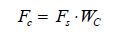
· Initial density of persons (d) : The initial density of persons in an escape route is the number of persons (p) divided by the available escape route area pertinent to the space where the persons are originally located and expressed from (p/m2).
· Specific flow of persons (Fs) : Specific flow of persons (p/ (m·s) )is the number of escaping persons past a point in the escape route per unit time per unit of clear width Wc of the route involved. Values of FS are given in Table 11 as a function of initial density.
| Type of facility | Initial densityd/ (p·m−2) | Specific flowFs / (p· (m·s) −1) | Initial speed of personsS/ (m·s−1) |
| Corridors | 0 | 0 | 1.2 |
| 0.5 | 0.65 | 1.2 | |
| 1.9 | 1.30 | 0.67 | |
| 3.2 | 0.65 | 0.20 | |
| ≥ 3.5 | 0.32 | 0.10 |
· Speed of persons (S) : The speed (m/s) of persons along the escape route depends on the specific flow of persons and on the type of escape facility. Person speed values are given in Table 12.
| Type of facility | Specific flowFs / (p· (m·s) −1) | Speed of personsS/ (m·s−1) |
| Stairs (down) | 0 | 1.0 |
| 0.54 | 1.0 | |
| 1.1 | 0.55 | |
| Stairs (up) | 0 | 0.8 |
| 0.43 | 0.8 | |
| 0.88 | 0.44 | |
| Corridors | 0 | 1.2 |
| 0.65 | 1.2 | |
| 1.3 | 0.67 |
· Calculated flow of persons (Fc) : The calculated flow of persons (p/s) is the predicted number of persons passing a particular point in an escape route per unit time, and is obtained from the following equation:
|
(2) |
Furthermore:
· Flow time (tF) : Flow time (s) is the total time needed for N persons to move past a point in the evacuation path, calculated as:
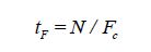
|
(3) |
where N is the number of persons.
· Stairway travel time (tstair) : Travel time (s) to traverse a stairway in order to reach the assembly station.
· Deck travel time (tdeck) : Travel time (s) to move from the farthest point of the escape route of a deck to the corresponding stairway.
· Assembly travel time (tassembly) : Travel time (s) to move from the end of the stairway to the entrance of the assigned assembly station.
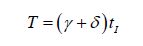
· Travel time (T) : Travel time expressed in seconds, calculated as:
|
(4) |
where γ is a correction factor, to be equal to 2 for day operating scenarios and 1.3 for night operating scenarios, Δ is the counter flow correction factor to be equal to 0.3, and tI is the sum of travel times (tstair, tdeck, and tassembly) expressed in seconds in ideal conditions.
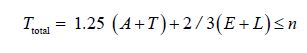
The calculation of the total time required for evacuation, Ttotal, as defined in the guidelines for evacuation analysis for new and existing passenger ships in MSC.1/Circ.1238//30 of the International Maritime Organization, 2007, is expressed as follows:
|
(5) |
where n= 60 for Ro-Ro passenger ships, A is the awareness time, which should be 5 min for daytime scenarios, E and L are the embarkation and launching times, respectively.
The embarkation and launching times should be calculated separately, based on the results of full-scale trials on similar ships and evacuation systems or on data provided by the manufacturers. For cases where neither of the two above methods apply, these times should be assumed to be 30 min.
Scenario 1: No fire/leakage at the area of the LNG tanks - summer, day operation
According to the class-approved ship evacuation plan, during summer operation, the following onboard distribution of people is assumed: 284 people located on the sun deck, plus 536 in the cocktail lounges.
To evacuate the ship, there are four available evacuation paths (in areas A, B, C, and D respectively, as shown in Fig. 14) by which the assembly stations on the lounge deck can be reached. Thus, a total of 71 people are assumed to be directed to each evacuation path.

|
| Figure 14 Sun deck: Four evacuation paths to stairways A, B, C, D are available |
First, we calculate the deck travel time tdeck, assuming a minimum speed of persons S equal to 0.67 m/s, as per Table 12 (corridor-type facility) for all four escape routes from the sun deck. We consider the remotest point of the deck to be that nearest the stairway. Table 13 summarizes the results. Note that the distance from the farthest point on the deck escape route to the corresponding stairway has been extracted from the approved plans of the vessel. The maximum value is considered (areas A & C).
| Sundeck area | Length/m | Speed/ (m·s−1) | tdeck/s | Comments |
| A | 14.59 | 0.67 | 21.78 | Value considered |
| B | 12.19 | 0.67 | 18.19 | |
| C | 14.59 | 0.67 | 21.78 | |
| D | 12.19 | 0.67 | 18.19 |
Next, we calculated the stairway travel time tstairs (time needed to descend the stairs to the lower deck). As listed in Table 12, the minimum speed of persons S equals 0.55 m/s (stairway-type facility) for the four escape routes. The corresponding results are summarized in Table 14.
To estimate the assembly travel time tassembly, we calculate the travel time to move from the end of each stairway on the lounge deck to the entrance of the assigned assembly station on the same deck (as shown in Fig. 15). We assume a minimum speed of persons S equal to 0.67 m/s, according to the figures in Table 12 (corridor-type facility) for all four routes on the lounge deck, and the corresponding results are summarized in Table 15.
| Stairways | Length/m | Speed/ (m·s−1) | tstairs/s | Comments |
| A | 3.8 | 0.55 | 6.91 | Same travel time applies for all cases |
| B | 3.8 | 0.55 | 6.91 | |
| C | 3.8 | 0.55 | 6.91 | |
| D | 3.8 | 0.55 | 6.91 |
| Assembly path | Length/m | Speed/ (m·s−1) | tassembly/s | Comments |
| A | 8.92 | 0.67 | 13.31 | Same travel time applies for all cases |
| B | 8.92 | 0.67 | 13.31 | |
| C | 8.92 | 0.67 | 13.31 | |
| D | 8.92 | 0.67 | 13.31 |

|
| Figure 15 Lounge deck assembly travel paths: Four paths are available, one from the end of each stairway to the entrance of the assigned assembly station |
In this evacuation scenario, we considered the following calculations of flow time: a) using the stairways (from the sun deck to the lounge deck) and b) using the corridors (entering the assembly stations on the lounge deck). We note that we extracted the value of the clear width (Wc) from the approved ship plans, and that the value for the specific flow Fs depends on the assumed initial density of people, which here is considered to be maximum (worst case). Thus, for a density of 3.5 p/m2, both for the stairs and corridors, the corresponding value for the specific flow Fs is equal to 0.32 p/ (m·s), as shown in Table 11. Furthermore, we considered that 71 persons (N) are directed to each evacuation path (i.e., to pass through each stairway and corridor), as stated above. The obtained results are summarized in Table 16.
| Type of facility | FS/ (p· (m·s) −1) | WC/m | FC=FS·WC/ (p·s−1) | tF= N/FC/s | Comments |
| Stairways | 0.32 | 1.2 | 0.384 | 184.90 | Value considered |
| Corridors | 0.32 | 1.3 | 0.416 | 170.67 |
As we can see from Table 16, the greater flow time tf is equal to 184.90 s, and we used this value to calculate the total travel times (tstair, tdeck and tassembly), which is equal to 226.89 s.
Next, we calculated the travel time T of Eq.(4), which is equal to 8.70 min. From Eq.(5), we calculated the total evacuation time Ttotal for the first case scenario to be 37.13min. As such, we can safely conclude that this result is acceptable (≤60 min).
Scenario 2: No fire/leakage in the area of the LNG tanks - summer, operation at night
In this case scenario, we consider different values for the correction factor (γ) and awareness time (A). Apart from the appropriate changes in these parameters, the analysis is exactly the same as in the previous analysis. Therefore, following the same procedure and assumptions as in the first case scenario, we obtained the travel and flow times for Scenario 2, as shown in Table 17.
| Deck travel time (tdeck) | 21.78 |
| Stairway travel time (tstairs) | 6.91 |
| Assembly travel time (tassembly) | 13.31 |
| Flow time (tF) | 184.90 |
| Sum of travel times (ti) | 226.89 |
Consequently, for this specific scenario, we used Eqs.(4) and (5) to calculate the travel time T=8.7 min and the total evacuation time, Ttotal=43.38 min, respectively. We can safely conclude that the Scenario 2 result is acceptable (≤60 min) as well.
Scenario 3: Fire/leakage in the area of the LNG tanks - summer, day operation
To define the third evacuation scenario, we assumed a fire/leakage at the LNG fuel tanks, which is causing possible obstructions or the unavailability of some evacuation paths. Specifically, the 284 passengers located on the sun deck should be directed only to areas B and D at the fore side of the vessel (as shown in Fig. 11), since areas A and C on the aft side of the ship are obstructed due to the fire/leakage at the fuel tanks.
In addition to the restriction of the evacuation paths, in our calculation of the deck travel time tdeck we must take into account the increased distance from the farthest point of the escape route of the sun deck to the corresponding stairway. As in the previous scenarios, we assumed a minimum speed for the passengers S of 0.67 m/s (according to Table 12) for both escape routes. The travel time results of the third scenario are summarized in Table 18.
| Sundeck area | Length/ m | Speed/ (m·s−1) | tdeck/s | Comments |
| B | 36.52 | 0.67 | 54.51 | Same travel time applies for all cases |
| D | 36.52 | 0.67 | 54.51 |
We note that the stairway travel time (tdeck) and the assembly travel time (tassembly) are not affected by the restriction of the evacuation paths and have the same values as in the previous scenarios, so their values are again 6.91 s and 13.31 s, respectively.
As stated above, we use Eqs.(2) and (3) to calculate the flow of persons Fc and flow time tF, respectively. In this scenario (Scenario 3), we consider that 142 persons (2×71) are directed to each evacuation path (i.e., to pass through each stairway and corridor), since only two paths are available. Note that the values for the clear width Wc and specific flow Fs are not affected and remain the same as in the previous scenarios. The obtained results from the flow time calculations are summarized in Table 19.
| Type of facility | FS/ (p· (m·s) −1) | WC/m | FC=FS·WC/ (p·s−1) | tF= N/FC/s | Comments |
| Stairways | 0.32 | 1.2 | 0.384 | 369.80 | Value considered |
| Corridors | 0.32 | 1.3 | 0.416 | 341.35 |
As we can see from Table 19, the higher flow time tf is equal to 369.80 s and this is the value we used in the calculation of the sum of the travel times tstairs+tdeck+tassembly+ tF=444.53 s. We calculated the travel time T from Eq.(4) as 17.04 min. From Eq.(5), we calculated the total evacuation time Ttotal for Scenario 3 to be 47.55 min. As such, we can safely conclude that this result is also acceptable (≤ 60 min).
Scenario 4: Fire/leakage in the area of the LNG tanks - summer, operation at night
In the fourth scenario, we consider a fire or leakage in the area of the LNG tanks during the night. The day and night cases differ in the awareness time (A) parameter. For the night case, the analysis is exactly the same as that previously presented (Scenario 3). Thus, the same procedures are followed and assumptions made as in the third scenario, and we obtained the travel and flow times shown in Table 20.
| Deck travel time (tdeck) | 54.51 |
| Stairway travel time (tstairs) | 6.91 |
| Assembly travel time (tassembly) | 13.31 |
| Flow time (tF) | 369.80 |
| Sum of travel times (ti) | 444.53 |
As in the previous three scenarios, we calculated the travel time T using Eq.(4), and obtained 17.04 min. We calculated the total evacuation time Ttotal for Scenario 4 using Eq.(5), and obtained 53.80 min. We can safely conclude that the result is acceptable (≤60 min) in this case also.
Scenario 5: Fire/leakage in the area of the LNG tanks - summer, operation at night, assuming an additional number of passengers located on the sun deck
To further evaluate the safety of the vessel evacuation procedures in case of an emergency, we analyzed a “worst case” scenario, in which a fire/leakage occurs in the fuel tanks area during night operation in summer, while an additional number of passengers are located on the sun deck.
In more detail, we considered that the passengers, assumed in the previous scenario (i.e., 284 in total), are sitting on the available seats while additional passengers are also present and occupying the available free space on this deck.
The free space on the deck, as estimated from the available plan, is equal to approximately 28 m2. Taking into consideration a maximum density of people of 3.2 p/m2, we can calculate the number of additional passengers to be 28m2×3.5 p/m2=98 persons. Thus, a total of 382 persons is assumed to be located on the sun deck.
To calculate the deck, stairway, and assembly travel times, the procedure is exactly the same as that previously presented, assuming a leakage or a fire at the fuel tanks at night (see Scenario 4). The results for these travel times are presented in Table 21.
| Deck travel time (tdeck) | 54.51 |
| Stairway travel time (tstairs) | 6.91 |
| Assembly travel time (tassembly) | 13.31 |
To estimate the flow time, however, we considered a total of 382 persons located on the sun deck. The corresponding calculations are presented in Table 22.
| Type of facility | FS/ (p· (m·s) −1) | WC/m | FC=FS·WC/ (p·s−1) | tF= N/FC/s | Comments |
| Stairways | 0.32 | 1.2 | 0.384 | 497.40 | Value considered |
| Corridors | 0.32 | 1.3 | 0.416 | 459.13 |
Similar to the times determined in the previous cases, the sum of the travel times is equal to 572.13 s. From Eq.(4), we calculated the total travel time to be 21.93 min. The total evacuation time for this scenario, as calculated using Eq.(5), is equal to 59.91 min.
The total calculated evacuation times determined for the five case scenarios in our study are presented in Table 23. It is easy to see that the necessary time for evacuation increases when a fire or leakage at the LNG fuel tanks is considered, since there is a restriction on the available evacuation paths, i.e., the two paths located on the aft side of the ship are not available for use. Nevertheless, no significant alteration in the evacuation plan is necessary (apart from the relocation of the helicopter pick-up area), since in all cases considered (even the worst case of Scenario 5), the total time for evacuation is still acceptable (i.e., ≤ 60 min).
| Evacuation Scenarios analysis | Total evacuation time | |
| Day | Night | |
| No fire/leakage at the area of the LNG tanks | 37.13 | 43.38 |
| Fire/leakage at the area of the LNG tanks | 47.55 | 53.80 |
| Fire/leakage at the area of the LNG tanks-Additional number of passengers present on sun deck | - | 59.91 |
To identify hazards related to LNG-fueled open-type ferry operation and to evaluate the severity and probability of each hazard, we carried out a HAZID study with the participation of a panel of local experts. The panel participants covered a wide range of the related stakeholders, including universities, a ship-class association, a research center, a transmission system operator, and a port authority. In total, 14 participants were involved. The HAZID study addressed all aspects of the proper transfer and maintenance of onboard LNG, as well as those related to the ship's normal operations during navigation or while in port.
In general, a HAZID study is a risk assessment method, and is, in fact, the first step of the Formal Safety Assessment (FSA) procedure of the IMO's MSC./Circ. 1023 (IMO, 2002). It uses a systematic process to identify hazards in order to plan, prepare, prevent, or reduce their impact. In order to perform this analysis, several steps must be completed. First, each hazard or threat must be identified, followed by the clarification of its cause. Once this has been achieved, the consequences of the related accident are determined, and the existing safeguards and barriers are evaluated with respect to their efficiency. As a final step, proper measures, referred to as Risk Control Options (RCOs), are outlined that will further reduce the risk generated by the potentially hazardous circumstances.
The framework applied in this HAZID study can be summarized as follows:
1) Identification of hazards related to the operational aspects of a diesel-LNG-fueled open-type ferry.
2) Identification of the relevant causes, consequences, and proposed appropriate RCO for each identified hazard.
3) Evaluation of the severity and probability of each hazard.
4) Ranking of the hazards in terms of risk.
As a first step, the members of the team defined the basic risk categories associated with each of the identified hazards. The following risk categories were considered:
1) Bunkering (61 hazards)
2) Evacuation (7 hazards)
3) Power supply systems (4 hazards)
4) Ferry loading/unloading (4 hazards)
5) Sailing/in port operations (15 hazards)
6) LNG storage system (11 hazards)
7) LNG distribution system (13 hazards)
Hazards covering various types of bunkering, such as truck-to-ship, ship-to-ship, and portable tanks, were taken into consideration. A total of 115 hazards were identified.
According to the IMO (2002) the risk of each hazard can be determined by multiplying its probability of occurrence with the resulting consequences from its occurrence:
|
(6) |
The IMO (2002) has proposed that the risk can be measured effectively on a logarithmic scale, so we can modify Eq.(6) to Eqs.(7) and (8), respectively:

|
(7) |

|
(8) |
where FI and SI correspond to frequency and severity indexes, respectively. The corresponding FI and SI values can be obtained from Tables 24 and 25, which include the typical range of the frequencies of occurrence (from events with a very remote likelihood to very likely events) and the severity of the consequences (from negligible to catastrophic). These values are provided by the IMO (2002) .
Each participant in the expert panel was assigned indexes of frequency and severity for the identified hazards. Taking into consideration all the possible combinations, we obtained a typical risk matrix, in which the risk values ranged from 2 to 13.
According to the IMO (2002) , the objectivity of this procedure is quantified and evaluated by calculating the concordance coefficient, which is deduced as follows:
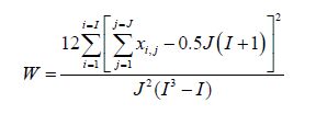
|
(9) |
where J is total number of experts participating in the hazards ranking, I is total number of accident scenarios which were evaluated, and xi, j is rank of each scenario ‘i' by expert ‘j'.
| FI | Frequency | Definition | F (per ship year) |
| 1 | Extremely Remote | Likely to occur once in the lifetime (20 years) of a world fleet of 5 000 ships | 10−5 |
| 2 | Very Remote | Likely to occur once per year in a fleet of 10 000 ships | 10−4 |
| 3 | Remote | Likely to occur once per year in a fleet of 1 000 ships | 10−3 |
| 4 | Little Probable | Likely to occur once per year in a fleet of 100 ships, i.e. likely to occur in the total life of a ship's life | 10−2 |
| 5 | Reasonably Probable | Likely to occur once per year in a fleet of 10 ships, i.e. likely to occur a few times during a ship's life | 10−1 |
| 6 | Probable | Likely to occur once per year on one ship | 1 |
| 7 | Frequent | Likely to occur once per month on one ship | 10 |
| 8 | Very Frequent | Likely to happen once or twice a week | 100 |
| SI | Severity | Effects on human safety | Effects on ship safety | Equivalent fatalities | |
| 1 | Negligible | Single or minor injuries | Equipment failure | 10−3 | |
| 2 | Minor | Single or major injuries | Local equipment damage | 10−2 | |
| 3 | Significant | Multiple or severe injuries | Non-severe ship damage (e.g. Port stay required) | 10−1 | |
| 4 | Critical | Single fatality or multiple severe injuries | Severe damage (e.g. Yard repair) | 1 | |
| 5 | Catastrophic | Multiple fatalities | Total loss | 10 | |
Depending on the calculated value of the concordance coefficient, the agreement on the ranking of hazards can be characterized as “poor” (0<W<0.5), “medium” (0.5<W<0.7), and “good” (0.7<W<1). In this study, the obtained value (W) was equal to 0.86, so the ranking of the hazards is considered to be solid. Tables 26 (a) and 26 (b) present the top five ranked hazards. The information presented in each line of the specific tables correspond to a particular hazard (the same procedure was followed for all 115 identified hazards). The overall results for each of the 115 hazards identified during the workshop can be found in Pirounakis et al.(2015) . As stated previously, we assigned each hazard to a basic risk category, and considered their possible causes and consequences, as well as the possible RCOs. Each RCO refers to human safety (S), environment (E), costs and finance (C), ship safety and technology (T). Additionally, we calculated the mean FI and SI values of all the values assigned by the participants.
The main hazards considered by the panel of experts include the following:
· Asphyxiation, which may be caused by the released LNG in a confined space or the presence of LNG in a space with no available breathing apparatus.
· Falling objects due to rough weather conditions in cases where objects are not properly tightened onboard.
· Lack of sufficient coordination and control during evacuation or, in the case of an existing ship's retrofitting, insufficient updating of the existing onboard evacuation arrangements. The main severe consequence of this hazard is the entrapment of crew members or passengers on the vessel.
· Fire or explosion in any part of the ship and particularly in the accommodation spaces and the garage.
· Long term lay-up of the ship onshore, which may cause a pressure build up in the tank if it still contains natural gas in liquefied form.
· Maintenance errors or manufacturing defects of the installed equipment (e.g., piping, hose connections, insulation, and instrumentation).
· Errors during the control or operation of the gas equipment or during bunkering.
· Collision or grounding of the ship, or heavy ship movements due to weather that impact the gas equipment.
· Human error during car loading/uploading.
The obtained risk matrix, grouped according to the basic risk categories, are presented in Fig. 16. As we can see, all hazards were ranked as below probable, in terms of their frequency of occurrence, whereas their severity rankings range from minor to catastrophic. Fig. 17 shows the risk ranking of the hazards, as per their risk characterization in the risk index (from low to extreme risk). The majority of hazards lie at the medium risk level. For those characterized as “high risk, ” the respective RCO should be applied to bring it into the medium risk level at the least. Finally, we carried out a statistical analysis based on the risk values of each hazard (115 in total) by considering the basic risk category to which each hazard belongs. Therefore, each category obtained a mean value (obtained from the risk index value of each hazard) and a respective standard deviation. Table 27 presents the results per category in terms of the ranking of their mean values, as well as their corresponding standard deviation for each category. Hazards during evacuation appear to be the most critical, followed by sailing and in-port operations.

|
| Figure 16 Obtained values in risk matrix |

|
| Figure 17 Ranking of hazards based on their risk index |
| Rank position | Hazard index | Hazards list | Cause | Consequence | |
| 1 | 2.5 | Asphyxiation | -Released natural gas in confined space - Lack of breathing apparatus |
- Loss of consciousness - Death |
|
| 2 | 6.10 | Falling objects | Rough weather conditions | Destruction of LNG tank outer shell | |
| 3 | 2.6 | Lack of sufficient coordination and control during evacuation | Human incompetence | - Extended evacuation time- More injuries - More fatalities |
|
| 4 | 5.12 | Fire/Explosion in machinery spaces | Fuel and oil leakages in the machinery room due to technical failure | - Damage of LNG system - Release of LNG - Loss of maneuverability - Loss of power - Injury of crew members |
|
| 5 | 1.22 | Gas dispersion cloud | Large release of LNG during bunkering | Possible fire, asphyxiation. | |
| Rank position | Hazards list | RCO | Category | Analysis | ||
| FI | SI | SUM | ||||
| 1 | Asphyxiation | -Installation of gas detectors - Provision of breathing apparatus |
S, C, T | 3.33 | 4.67 | 8.00 |
| 2 | Falling objects | Lashing of objects | S, T | 4.50 | 3.50 | 8.00 |
| 3 | Lack of sufficient coordination and control during evacuation | - ISM - Fire control plan -Emergency preparedness, - SOLAS |
S, T | 4.00 | 3.67 | 7.67 |
| 4 | Fire / Explosion in machinery spaces | - Installation of detectors - Fire mitigation systems - Structural fire integrity - Shielding of pipes and LNG pipes - Testing and maintenance of ESD system or correct application of the inherently gas safe system |
S, T, E | 3.33 | 4.33 | 7.67 |
| 5 | Gas dispersion cloud | Hazardous zones establishment. | S, E | 3.00 | 4.50 | 7.50 |
| Rank | Risk category | Mean RI | st. dev RI |
| 1 | Evacuation | 6.67 | 0.89 |
| 2 | Sailing/in port operations | 6.27 | 0.85 |
| 3 | Ferry loading/unloading | 6.00 | 0.46 |
| 4 | LNG storage system | 5.85 | 0.50 |
| 5 | Power supply systems | 5.75 | 0.35 |
| 6 | LNG distribution system | 5.63 | 0.74 |
| 7 | Bunkering | 5.48 | 0.67 |
Most of the existing ship-fire insulation is of Class A-60 standard, although in certain areas of the ship this standard is not required by the corresponding class regulations. To comply with the class requirements when using LNG fuel, the modifications to the vessel's fire insulation involve: Class A-60 standard insulation of the docking station and superstructure where the LNG tanks are located, the replacement of the windows in the accommodation space facing the LNG tanks with Class A-60 type insulation sheet, replacement of bridge windows facing the LNG tanks by Class A-0 standard windows, Class A-60 type insulation along the side of the stairways facing the tanks.
The vessel is already equipped with appropriate fixed fire extinguishing systems, i.e., sprinkler/drencher systems and a CO2 system. No alteration is necessary for these systems since both engine rooms are considered to be inherently safe and there is no bunkering station installed onboard. Furthermore, the fixed fire extinguishing system should be equipped with an appropriate water spraying system for cooling and fire prevention of the exposed parts of the LNG storage tanks above deck. We investigated the need for additional water supply (with respect to the ship's already installed fire pumps) along with the necessary modifications of the ship's existing fire line. As the ship is already equipped with an additional fire pump with respect to the minimum required for its class, we recommend that one pump be dedicated to the LNG water spray system.
3.2 Fire detection systemNecessary modifications are focused on the topology of the existing fire system, the use of heat detectors rather than smoke detectors, and the installation of gas detectors in certain areas of the ship. Furthermore, we carried out an initial compatibility investigation of the existing fire detection system and its automated interface with regard to the LNG fuel supply interface, based on the assumption that a typical commercial solution for a cassette-type tank would be installed on board for LNG storage. We determined that the existing fire detection unit onboard provides sufficient control signals-relay outputs for fire detection, and that the fire detectors to be installed inside the LNGPacTM system can be connected to an appropriate fire zone of the existing system.
We recommend the installation of an appropriate gas detection system, including the provision of details regarding a commercially available system, such as the system's type, the employed sensor's topology, and the appropriate interface to the LNG fuel supply automation system.
3.3 Ventilation systemIn this analysis, we mainly investigated the system's current topology and calculated the additional capacity of air supply required for the machinery spaces, taking into account the type of machinery room, the minimum number of required air changes inside the dual-pipe LNG fuel lines, and the necessary additional equipment. The existing ventilation system of the engine rooms is sufficient. In addition, we recommend that a separate ventilation system be installed onboard, dedicated to the ventilation of the double-wall fuel line, that is, we recommend that two ventilation fans of the same power rating be installed on top of the superstructure of the LNG storage tanks.
3.4 Evacuation analysisWe analyzed and presented five evacuation scenarios involving the ship's summer operation, during the day and night, in order to identify the possible alterations that may be required in the evacuation plan of the ship. We found, as expected, that the necessary evacuation time increases when fire/leakage at the LNG fuel tanks is considered, due to restrictions in the available evacuation paths during night operation. There is no need for significant alteration of the ship's evacuation plan, since the evacuation times are acceptable within the imposed regulations.
3.5 HAZID analysisWe carried out a HAZID study in order to identify the main hazards related to LNG-fueled open-type ferry operation, and to evaluate the severity and probability of each hazard. The majority of hazards lie within the “medium risk level, ” while the identified hazards during evacuation appear to be the most critical, followed by hazards related to sailing and in-port operations.
4 ConclusionsIn this paper, we presented our considerations of the conversion of an open type Ro-Ro passenger ferry with regard to its safety systems for the implementation of LNG fuel. The basic requirements with which the ship already complies are reported, along with the additional requirements imposed by national and international classification societies for LNG-fueled ships. We investigated all the necessary modifications that must be considered for each safety system. Furthermore, we performed an appropriate evacuation analysis and a HAZID study in order to identify the main operational hazards when taking into consideration the use of LNG fuel. The main conclusions of the study for this type of ship can be summarized as follows:
1) No major modifications of the ship's existing fire and safety systems are required to conform to the safety regulations for LNG fuel. A separate water spray line for the LNG tanks should be installed.
2) The installation of an appropriate gas detection system should be made.
3) The installation of a separate ventilation system dedicated to the ventilation of the double-wall fuel line should be made.
4) No significant alteration in the evacuation plan is necessary, since the total time required for evacuation is acceptable in all the scenarios considered.
5) The most critical hazards identified in the performed safety assessment of the converted dual fuel ship are related to evacuation, sailing, and in-port operations.
From the outcome of this investigation, we conclude that the required modifications to the ship's safety systems in order to use LNG fuel are viable. Although the type of our vessel covers a wide range of similar cases, the specific results should not be generalized for every case due to the potential differences in the particular design of each vessel.
AcknowledgementThis work was conducted within the framework of the project LNG-COMSHIP (Greek General Secretariat of Research and Technology Code: 12CHN400, and was funded by the European Regional Development Fund (ERDF) and National Resources.
| Aronietis R, Sys C, Vanelslander T, 2014. Ship retrofit solutions: economic, energy and environmental impacts. Ehlers S, et al. (Eds). Maritime-port technology and development, CRC Press, 57–66. |
| Autronica Fire and Security AS. 2015a. Installation and commissioning handbook. Fire Alarm Control Panel BX-10. P-BX10/IE- Rev. L. 040504, Autronica, Fire and Security AS, Trondheim. |
| Autronica Fire and Security AS. 2015b. Fixed gas detection system. Type OGS 2.1 datasheet. Autronica fire and security A.S, Trondheim. |
| Bui Y. 2015. A complete solution for LNG fuelled ships. [2015-01-29]. Available from http://www.wartsila.com |
| Council Directive 98/18/EC. 1998. Safety rules and standards for passenger ships. Eurosolas 98/18. The Council of the European Union. |
| Curt B. 2004. Marine transportation of LNG. Intertanko Safety, Technical and Environmental Committee (ISTEC) Meeting, Dubai. |
| GL. 2010. Additional rules and guidelines: guidelines for the use of gas as fuel for ships. In Rules for classification and construction, Germanischer Lloyd, Hamburg. |
| HRS. 2015. Rules and regulations for the construction and classification of steel ships. Hellenic Register of Shipping, Piraeus. |
| IMO. 2002. Guidelines for formal safety assessment (FSA) for use in the IMO rule-making process. IMO MSC./Circ.1023. International Maritime Organization, London. |
| IMO. 2007. Guidelines for evacuation analysis for new and existing passenger ships. IMO MSC.1/Circ.1238. International Maritime Organization, London. |
| IMO. 2009. Second IMO GHG study. International Maritime Organization, London. |
| IMO. 2012. Revised guidelines for the design and approval of fixed water-based fire-fighting systems for Ro-Ro spaces and special category spaces. IMO MSC.1/Circ.1430 Resolution A.123(V). International Maritime Organization, London. |
| Jacobs P. 2012. A technical summary of the integrated package provided by Wartsila. SNAME GL&GR Meeting, Cleveland. |
| Martek Marine Ltd, 2015. Addressable gas detection system, MM2000TM datasheet. Rotherham: Marine Ltd. |
| Mizithras P, Pirounakis D, Krimitzas K, Zoulos A, Matsagou M, Sakellaris D, Senis D, Kapsopoulos M, Konstantinou E, Venizelos A. 2015. Review of the existing safety and security regulations for LNG fuelled ships. LNG-COMSHIP project deliverable D4.1, Hellenic Register of Shipping, Piraeus. |
| Pagonis D-N, Dimitrellou S. 2014. Implementation of LNG fuel to an existing RoRo-Passenger ship, Preliminary design study results. LNG-COMSHIP Workshop, Athens. |
| Pirounakis D, Mizithras P, Savvoglou C, Sempsis L, Krimitzas K, Zoulos A, Matsagou M, Sakellaris D, Senis D. 2015. Formal safety assessment of the converted diesel-LNG dual fuel ship. LNG-COMSHIP project deliverable D4.2, Hellenic Register of Shipping, Piraeus. |
| SOLAS, 1974. International convention for the safety of life at sea as amended. London: International Maritime Organization. |
| Theotokatos G, Livanos GA, Dimitrellou S, Strantzali E, Pagonis D-N, Politis K, Theodoulides A, Peirounakis D, Mizithras P, 2015. Design of LNG storage and feeding system for an open type ferry. Proceedings of the 16th International Congress of the International Maritime Association of the Mediterranean, Pula, 473–481. |
| Word Ports Climate Initiative. LNG fuel vessels. [2016-03-23]. http://www.lngbunkering.org/lng/vessels/ferries |