


 ,
,
1 Introduction
Convergent Vortex Tubes (VTs) have been extensively applied in gas purification control during the 20th century. These tubes are typically used as the main and preliminary controller tools for the purification of the fuel gas entering the big engines (e.g., ship or submarine engines) owing to their easy installation and construction as well as low maintenance or operation costs. Furthermore, convergent VTs are preferred for the recycling and separation of valuable materials in several powdered production processes. The VT, also called a “separator” in relation to its invention and development (Ranque, 1933; Hilsch, 1947), is a useful device that has many applications despite its simple structure. When pressurized gas (or liquid, such as a hydrocarbon mixture) is injected through the slots into the chamber of the VT cyclone separator, the temperature of the escaping flow at the central exhaust near the vortex chamber or slots area is lower than that of the flow coming in from the storage tank; simultaneously, the temperature of the flow exiting from the circumferential exhaust at the other side of the cyclone separator tube is higher than that of the inlet flow. The structure of the VT cyclone separator system can be divided into a number of components, including a cold end orifice, a vortex chamber, a number of nozzle slots, a main or hot tube, and a control valve. The gas or fluid is pressurized by a compressor and is stored in the storage tank. This pressurized gas is transported through the pipes and then injected into the chamber via the nozzle slots. The tangential injection of the pressurized gas creates the strong rotating layers of gas inside the cyclone separator. The gas is injected tangentially via the nozzle slots and rotates around the central axis of the main tube until the gas expands and cools. After the occurrence of flow separation inside the main tube, the input gas through the nozzle slots is divided into two streams (hot and cold) with large temperature differences. The first output is known as “cold exhaust” and is located close to the nozzle slots. The hot exhaust is located on the other side of the main tube, and this output is covered by a control valve that controls the rate of the hot flow. Opening the mentioned valve leads to an increase in the flow rate at the hot exhaust; consequently, the cold air flow rate is reduced. The VT cyclone separator performance can be easily managed with the control valve. Several scientific works have been conducted to develop the VT cyclone separator structure and examine its efficiency. Here, we look at a brief review of some of these studies. Dutta et al. (2011) tried to apply a CFD model for analyzing the fluid flow inside the main tube using the NIST real gas model. Baghdad et al.(2011) examined the prediction ability of several numerical models (the k-ɛ, k-ω and SST k-ω). The effect of the main tube bending on the VT cyclone separator efficiency is studied by Valipour and Niazi (2011) , Bovand et al.(2014a; 2014b), and Rafiee et al.(2016) . Dincer (2011) tested three different types of the VT cyclone separator (the conventional VT, three-fold cascade type VT, and six cascade type RHVT) under different pressure injections. Some structural parameters (e.g., the length of the straight main tube, the cold and hot exhausts, the nozzle area ratio, and the inlet slots) have been optimized by Im and Yu (2012) . Through laboratory work, Han et al.(2013) and Rafiee and Sadeghiazad (2016a) examined the effects of applying different types of inlet gases (i.e., N2, O2, CO2, R32, R728, R134a, R744, R161, and R22) on the heating and cooling performance of a VT cooling system based on pressure analysis. Thakare and Parekh (2015) numerically studied the effect of this operating parameter (different working gases). Mohammadi et al.(2013) tested a cooling VT cyclone separator system to optimize the number and the diameter of the nozzles, the cold mass ratio, and the intake pressure. Some researchers (Rafiee and Sadeghiazad, 2014a; Shamsoddini and Hossein Nezhad, 2010) focused on the effect of nozzle numbers and proved that the straight VT cyclone separator with the higher number of nozzles has greater cooling power compared with the separator with less nozzles. A new type of nozzle, the convergent nozzle, has been tested and optimized by Rafiee and Rahimi (2013) . They also demonstrated that if the velocity of the gas entering the chamber increases, then the efficiency of the straight VT cyclone separator can be improved to a certain extent. The separated flow hysteresis phenomenon that occurs during the process of streamlining the gas-turbine engine’s axial compressor has been analyzed by Kulyk et al.(2012) . Moreover, the accuracy of different turbulence models in predicting the separation phenomenon has been analyzed by Rafiee and Sadeghiazad (2016b) . The geometrical optimization techniques are usually applied in order to increase the energy separation rate and thermal efficiency; doing so optimizes the dimensions of the straight VT cyclone separator system, thereby decreasing the operating costs. Various methods, such as the exergy analysis, have been successfully used to optimize the structural parameters of the straight VT cyclone separator (Saidi and Allaf Yazdi, 1999; Ouadha et al., 2013; Rafiee and Sadeghiazad, 2014b). Secchiaroli et al.(2009) conducted a numerical investigation to analyze the internal flow in a straight VT cyclone separator, which is used in a jet impingement system. Some numerical methods, such as the Taguchi methods (Pinar et al., 2009), the neural networks (Korkmaz, 2012), and the Rule-Based Mamdani-Type Fuzzy (RBMTF) modeling technique (Berber et al., 2013), have recently been used to optimize the operating conditions of the straight VT cyclone separator. Rafiee and Sadeghiazad (2015) analyzed the effect of rounding off edge radius on the energy separation inside a vortex tube. Saidi and Valipour (2003) classified the parameters influencing the thermal performance of the straight VT cyclone separator into two categories: thermo-physical and structural categories. The influence of the geometrical parameters of the nozzle intakes, such as the internal diameters, has been experimentally investigated by Aydin and Baki (2006) . Rafiee et al. (2015) evaluated the effect of cold orifice diameter on flow separation inside a convergent vortex tube. A special type of VT is the divergent VT, which in some small angles can have better performance than the straight ones (Chang et al., 2011; Rahimi et al., 2013). Meanwhile, Dincer et al.(2008) and Agrawal et al.(2014) have accomplished complete experimental works on the straight VT cyclone separator with various length to diameter ratios (L/D). The secondary circulation inside the straight VT cyclone separator has been explained and described by Ahlborn and Gordon (2000) . There are many benefits that can be gained from using CFD numerical models. One of these advantages is that the CFD models present a clear and detailed description regarding the thermal distribution and the velocity field inside the straight VT cyclone separator (Akhesmeh et al., 2008; Rafiee and Rahimi, 2014; Aljuwayhel et al., 2005; Skye et al., 2006). Two detailed reviews (Subudhi and Sen, 2015; Thakare et al., 2015) have been presented ibn relation to the contents of the VT cyclone separator. Piralishvili and Polyaev (1996) and Alekhin et al.(2015) introduced a new type of VT cyclone separator, which is a double-circuit VTs wherein an additional inlet is added on the hot throttle valve. Kandil and Abdelghany (2015) assessed the effects of some geometrical parameters, such as the L/D, on the straight VT cyclone separator performance. Pourmahmoud et al. (2013) reported that the best working fluid to create the maximum cold temperature difference is CO2. Liu and Liu ( 2014) proposed a three-dimensional (3D) model for predicting and calculating the temperature and velocity distributions, which in turn, are used to describe the energy and the gas separation phenomenon inside the straight VT cyclone separator. Meanwhile, Pourmahmoud et al.(2012a) reported that the cold temperature difference can be improved using the helical nozzles. The effect of inlet temperature is analyzed by Pourmahmoud et al. (2014). Khazaei et al.(2012) found that the size of the hot exhaust does not affect the thermal efficiency of the straight VT cyclone separator, whereas Li et al.(2015) demonstrated that the increase of the cold flow fraction (or the decrease of the pressure at injectors) moves the stagnation point to the cold end. Rafiee and Sadeghiazad (2014c) studied the influence of control valve angle on flow separation inside a vortex tube. Gutak (2015) utilized a straight VT cyclone separator with high pressure natural gas stream and found that the Joule-Thomson effect has an important influence on the energy distribution process. Rafiee et al.(2013) performed a numerical work on optimization of working tube radius for a normal vortex tube. Mohammadi and Farhadi (2014) analyzed the separation process and the gas fractions inside a straight VT cyclone separator for a hydrocarbon mixture. The hot tube length is optimized (in a numerical study) by Rafiee and Sadeghiazad (2016c) . Khait et al.(2014) employed the RSM turbulence model to introduce a comprehensive CFD model for predicting the flow distribution inside the straight VT cyclone separator. Rafiee and Sadeghiazad (2016d) optimized the vortex chamber radius based on a three dimensional model. The annular straight VT cyclone separator, in which the hot flow is redirected on the hot tube, has been introduced by Sadi and Farzaneh-Gord (2014) . Rafiee and Sadeghiazad (2016e) optimized (numerically and experimentally) the control valve diameter for a convergent vortex tube. Pourmahmoud et al. (2012b) optimized the angle of a convergent nozzle to improve the performance of a common vortex tube. Bej and Sinhamahapatra (2014) worked on the hot cascade-type straight VT cyclone separator, in which the hot gas flow exiting the first VT cycle is utilized as the inlet of the second VT cycle. The concept of the nozzle aspect ratio and its effect on the separation phenomenon are studied in an experimental work by Avci (2013) . Rafiee and Sadeghiazad (2017) analyzed the effect of control valve shape on energy separation inside a straight vortex tube. However, the optimization of the separation process inside the convergent VT cyclone separator and the impact of its geometrical parameters on cooling/heating effectiveness have not been analyzed in previous works. Despite the need to employ convergent vortex tubes in special industries, to the best of our knowledge, no comprehensive analysis on the convergent VT separation process can be found in the related literature. Therefore, such research gap motivated us to conduct a comprehensive study on the separation performance of convergent VTs. We believe that, the appropriate and precise design of the throttle valve angle, slot number, and injection pressure can improve the cooling and heating performances of the convergent VT.
2 Experimental studyThe detailed structural plot of the convergent VT is shown in Fig. 1. This laboratory setup focuses on the separation phenomenon of the compressed air and the operational fluid. A steel convergent VT is designed with structural parameters as shown in Table 1.

|
| Figure 1 A schematic drawing of the convergent air separator with geometrical parameters |
| Length of convergentmain tube/mm | 185 |
| Diameter of cold exhaust/mm | 9 |
| Slot number | 2, 3, 4, 6 |
| Shape of the control valve | Truncated cone |
| Nozzle section | 2×1.7 |
| Angle of the throttle valve/ (°) | 30, 40, 50, 60, 70, 80, 90 |
| Convergence angle/ (°) | 2 |
| Throttle diameter/mm | 5.5 |
The schematic diagram of the experimental setup utilized in the investigation is shown in Fig. 2. The system was designed so that all components can be easily changed, especially the conical valve and the convergent main tube. With this adjustable design, the authors were able to study the effects of several structural parameters on the convergent VT performance. Room temperature was set at 21 ℃ during the tests. The measuring instruments with details are listed in the Table 2.

|
| Figure 2 A schematic drawing of the experimental setup |
| Instrument | Accuracy |
| Pressure sensor BD 26.600G (0 to 1.4 MPa) | ≤1% |
| Rotameter (DK800S-6) | ±1% |
| Thermometer PT 100/℃ | ±0.2 |
| Humidity sensor 10-95 (% R.H.) | 3% |
Seven different hot control valves with various angles were manufactured and used in the tests. Two Ø2 mm holes were drilled on the VT cyclone separator axis so that the thermo probes can be adjusted. The distances between the exhausts (cold and hot) and the holes were set at 1.25 cm. Prior to conducting the tests, the hot valve was adjusted in the open condition. The tank started to work in the next stage. The pressure (0.45 MPa) in the cycle was supplied by the action of the valve set on the inlet of the VT cyclone separator. The pressures and the mass rates were measured by the pressure sensors and the rotameters during the tests, respectively. Then, each convergent VT with specified parameters was tested. The test processes were repeated several times for each parameter in order to determine the reliable values for the exhaust temperatures and pressures. Photographic images of some control valves (in comparison form) used in the tests are shown in Fig. 3.

|
| Figure 3 Photographs of control valves with different throttle angles (in comparison form) used in the tests |
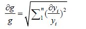
In this section, the uncertainty and the error analysis regarding the measurements of the pressure and temperature are discussed. A differential method has been presented by Moffat (1985) to estimate the maximum temperature and pressure uncertainties. This method uses two parameters, namely, instrument accuracy and minimum values of output for estimating the errors. We assumed that an especial quantity, such as g, is calculated by some independent variables, such as yi, so the value of error for gcan be estimated by using the equation
|
(1) |
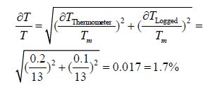
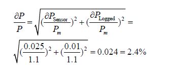
where yi, $\partial {y_i}$, $\frac{{\partial {y_i}}}{{{y_i}}}$ and represent the minimum value of the independent parameter, the measuring instruments accuracy, and the error of the independent parameter, respectively. The accuracies of the pressure and the temperature are 0.002 5 MPa and 0.2 ℃, respectively. The logged pressure and the temperature accuracies are 0.001MPa and 0.1 ℃. Thus, we can calculate the maximum errors for the pressure and the temperature by using the equations given below.
|
|
The fluid stream has a compressible pattern with the high rotational specifications. Thus, the RSM turbulence model was applied to solve the nonlinear equations (conservation of momentum, mass, and energy equation) of flow streams inside the tested convergent VT cyclone separator. A 3D numerical model was developed to predict the fluid treatment inside the convergent VT. This model was employed to create an accurate validation between the experimental and the numerical outputs. This model was executed by a finite volume commercial code (Fluent 6.3.26) using the steady state conditions. Then, we used the equations of conservation of mass, momentum, and energy, which are provided below.
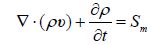
The continuity equation is given by
|
(2) |
The fluid flow in the present work is considered to be steady, so the term $\frac{{\partial \rho }}{{\partial t}}$ is equal to zero. If any mass flow is entered into the domain, the term Sm is added to the equation. In other words, this term refers to the additional mass entering the main domain.
The momentum equation is given by
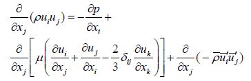
|
(3) |
and the energy equation is expressed as
|
(4) |
The influence of the compressibility is assumed as below, in which the working fluid is assumed to be an ideal gas

|
(5) |
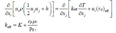
The Fluent software provides the Reynolds Stress Model (RSM) as the most elaborate numerical modeling to simulate the full turbulent rotational flows. The transport equations were solved together with the equation of dissipation rate to close the Reynolds-averaged Navier-Stokes equations by the RSM (abandoning the isotropic eddy-viscosity assumption). Thus, seven transport equations are solved in the 3D issues, whereas five transport equations are required to be solved in the two-dimensional (2D) problems. This model has several advantages compared with other models, such as the two-equation or one-equation models. Some of these benefits are as follows: (a) consideration of the streamline curvature effect and involvement of the impact of the sharp changes in the rate of strain, and (b) the ability to modelthe high rotational and swirl patterns. Such excellent performances convinced the researchers to use this model despite the lengthy amount of time required to solve the 3D problems. The main transport equations of the Reynolds stresses, $\rho \overline {{{u'}_i}{{u'}_j}} $, can be written as
|
(6) |
where Suser, Fij, ɛij, ϕij, Gij, Pij, DL, ij, DT, ij, Cij, and $\frac{\partial }{{\partial t}}(\rho \overline {{{u'}_i}{{u'}_j}} )$ are considered as user-defined source term, production by system rotation, dissipation, pressure strain, buoyancy production, stress production, molecular diffusion, turbulent diffusion, convection, and local time derivative, respectively. In Eq.(6), some terms, such as Fij, Pij, DL, ij, and Cij do not require any discretizing. However, other terms (ɛij, ϕij, Gij, and DT, ij) should be discretized and modeled to manage Eq.(6).
3.2 Physical simulation 3.2.1 ModelingThe 3D numerical model developed in the numerical section was created on basis of the exact structural parameters of the real model. This means that the geometrical parameters are completely similar to the laboratory model (Table 1). In the numerical simulation and the experimental study, the cold diameter of the convergent VT was set at 9 mm as the fixed property. The flow pattern and the rate of energy separation were adjusted by changing the mentioned parameters (throttle angle and slots number), and then these changes appeared as changes in output temperatures. This research used a 3D model to provide a clear observation of the process of energy separation inside the convergent VT. The variations in the axial and tangential velocities and the total pressure were then compared to analyze the flow properties. There are different meshing methods (unstructured and structured), and each can be used in different geometries. Here, a better mesh quality leads to a greater and faster convergence rate. In other words, the correct solution has been achieved faster. The accuracy of the results is very important near the outlets; thus, this issue shows the importance of using the finer mesh grids near the hot and cold outlets (Fig. 4 (a) ). A normal VT cyclone separator with the straight main tube is shown in Fig. 4 (b) (compared with convergent one). In the following, we have a solution with more accuracy using better mesh quality. Furthermore, the CPU time is an important factor in the computational problems. In some problems, in which the quality of the arrangement of the cells is not efficient, the CPU time needed can be relatively increased. The CPU time is typically proportional to the quality of the mesh grids. In 3D modeling, there are 3D e lements involved, namely, hexahedron, quadrilateral pyramid, and tetrahedron. For the same number of elements, the accuracy of solutions has the highest value using the triangular prism and the hexahedral meshes. Hence, these two types of mesh units were used in the developed model, as seen in Figs. 4 (c) and 4 (d) , respectively. The volume around the center line of the VT cyclone separator was arranged by the triangular prism units; consequently, the rest volume was made by the hexahedral meshes. In this way, both time and accuracy were combined to produce reliable results.

|
| Figure 4 Schematic demonstration of the mesh domain and the shape of the unit volumes |
Given that the turbulence intensity of the air flow in the VT cyclone separator is very high, the conventional numerical methods do not have the ability to solve the equations in this instrument. The Under-Relaxation Factors (URFs) play an important role in the process of the computation, that is, such factors determine the development path of the calculations. The calculations should be a step-by-step process, and the number of stages is determined by the URFs. In fact, the calculation significantly increases the stability of the solution. In this article, the URF changes are proposed to solve the equations of the flow pattern in the convergent VT cyclone separator to be used by researchers (Table 3). First and Second Order Schemes (intermittent) were applied for the pressure discretization, because according to the CFD experiences, these combinations work better than other schemes for both the swirling flow with high rotational speed (1 000 000 r/min) and the steep pressure variation. Furthermore, the SIMPLE algorithm was added to the computations for the pressure-velocity coupling. The computation continues as long as the calculations are converged. In this research, the convergences occurred in the range of 150 000 to 210 000 iterations. The step-by-step changes of the URF values are presented in Table 3.
| Item | Default | Step | ||||||||||
| URF | 1 | 2 | 3 | 4 | 5 | 6 | 7 | 8 | 9 | 10 | 11 | |
| Energy | 1 | 0.1 | 0.2 | 0.3 | 0.4 | 0.5 | 0.6 | 0.7 | 0.8 | 0.9 | 0.95 | 1 |
| Turbulent dissipation rate | 0.8 | 0.1 | 0.1 | 0.2 | 0.2 | 0.3 | 0.4 | 0.5 | 0.5 | 0.6 | 0.7 | 0.8 |
| Body force | 1 | 0.1 | 0.2 | 0.3 | 0.4 | 0.5 | 0.6 | 0.7 | 0.8 | 0.9 | 0.95 | 1 |
| Reynolds stresses | 0.5 | 0.1 | 0.15 | 0.2 | 0.25 | 0.3 | 0.35 | 0.4 | 0.45 | 0.45 | 0.5 | 0.5 |
| Density | 1 | 0.1 | 0.2 | 0.3 | 0.4 | 0.5 | 0.6 | 0.7 | 0.8 | 0.9 | 0.95 | 1 |
| Turbulent viscosity | 1 | 0.1 | 0.2 | 0.3 | 0.4 | 0.5 | 0.6 | 0.7 | 0.8 | 0.9 | 0.95 | 1 |
| Turbulent kinetic energy | 0.8 | 0.1 | 0.1 | 0.2 | 0.2 | 0.3 | 0.4 | 0.5 | 0.5 | 0.6 | 0.7 | 0.8 |
| Momentum | 0.7 | 0.1 | 0.1 | 0.2 | 0.2 | 0.3 | 0.3 | 0.4 | 0.4 | 0.5 | 0.6 | 0.7 |
| Pressure | 0.3 | 0.1 | 0.1 | 0.3 | 0.1 | 0.2 | 0.2 | 0.2 | 0.3 | 0.3 | 0.3 | 0.3 |
The computational domain requires the boundary conditions shown in Fig. 5.

|
| Figure 5 Boundary conditions required for the simulation |
At the hot exit (bottom) and the cold exhaust (top) of the CFD domain, the pressure outlet boundary conditions were assumed. On the wall of the 3D model, the adiabatic boundary condition was applied (no heat transfer occurred between the convergent VT cyclone separator and the ambient air); consequently, the convection effect was neglected here. A no-slip boundary condition between the wall and the rotational flow existed inside the VT cyclone separator. The other boundary condition was that the nozzle slots (injectors) were set as the pressure inlet (Experimental values) with the pressure 0.45 MPa. The slot surface temperature was adjusted to 294.2 K (ambient temperature). The operating fluid inside the convergent VT cyclone separator was considered to be air with the ideal gas properties (λ=1.4). The boundary conditions can be summarized below.
1) At the slots of the injectors, the boundaries are modeled as the pressure inlet, with the specified pressure value at 0.45 MPa and the fixed stagnation temperature at 294.2 K.
2) Cold and hot exits were set as the pressure outlet.
3) The walls around the domain were set as the adiabatic boundary conditions, which also possessed no-slip properties.
3.3 Grid independence studyPrior to conducting numerical modeling, calculation, or simulation, the grid independence check is very important. For this reason, six different numbers of the unit cell volumes were examined, as reported in Table 4. A convergent VT cyclone separator with a truncated cone throttle valve (for β=2°, α=30°, Dth=5.5 mm, Lconvergent= 185mm and Dcold=9 mm as the basic model) was modeled with different unit cell volumes to guarantee the mesh sensitivity and the grid independence of the numerical outputs. Table 4 focuses on the predicted cold temperature difference at the location of the cold exhaust for the domains with 0.95 million (denoted as “coarse”); 1.12 million and 1.44 million (denoted as “medium”); and 1.67 million, 2.02 million, and 2.35 million (denoted as “fine”) unit volumes. The influence of the mesh resolution and the discretization schemes can be explained (in this case) by comparing the cold temperature differences (Table 4). As seen in Table 4, the comparison of different unit cell volumes or the resolution of the mesh grids proves that the calculation obtained by applying 2.02 million units can be used in the mesh independent model; this is because the relative difference in maximum cold temperature (cold mass fraction 0.27) applying 2.02 million units and 2.35 million units (denoted as “fine”) is less than 1.6%. This finding indicates that enhancing the unit volume number does not have an effect on the accuracy of the results. To decrease the computational time and the cost, we choose 2.02 million unit cell volume in all our models.
| Number of grids (million) | Predicted cold temperature difference |
| 0.95 | 17.58 |
| 1.12 | 18.98 |
| 1.44 | 20.18 |
| 1.67 | 21.43 |
| 2.02 | 22.57 |
| 2.35 | 22.95 |
To obtain a clear insight into the effects of throttle angle, slot number, and injection pressure on the separation capabilities of the convergent VT (resulting from the exhausts), some experiments and numerical simulations as parametric studies were conducted. This research focuses on the use of the convergent VT cyclone separator in various structural conditions. This is done so that we can determine which operating condition or structural parameter has a sensitive effect on the separation performance of the VT cyclone separator equipped with convergent main tube. We present the optimum values for the mentioned parameters to create the best possible separation capability (for the convergent VT cyclone separator) by applying both experiments and CFD methods (RSM). The experiments included (a) testing the effects of seven different throttle angles (30°-90°), (b) determining the effects of applying different slot numbers (inside the chamber), and (c) testing the thermal reactions of the convergent VT cyclone separator against different operating pressures (Pi=0.45, 0.55, 0.65 MPa with compressed air). The separation capabilities of the convergent VT cyclone separator can be represented as ΔTc and ΔTh, which are respectively defined as:
|
(7) |
|
(8) |
The cold flow fraction is an important factor in the calculation of the convergent VT cyclone separator efficiency, because this is an output parameter that defines the flow rate of the cold exhaust. This important parameter is obtained by dividing the rate of the cold flow by the rate of the inlet flow, as shown in Eq.(9)

|
(9) |
As previously mentioned, the cold air flow is managed by the control valve performance, which has a direct impact on the separation efficiency. Therefore, the optimal design of this part of the system can have a significant influence on the performance of the convergent VT separator system. In the first step, we optimized this part of convergent VT cyclone separator.
4.1 Experimental results 4.1.1 Effect of throttle angleSeven control valves with the various throttle angles were used in this part of the experimental analysis. The throttle angles were α=30°, 40°, 50°, 60°, 70°, 80°, and 90°. The throttle diameter of Dth=5.5 mm was used as a fixed parameter. The impact of the throttle angle of the control valve on the separation performance of the convergent VT cyclone separator has yet to be analyzed, although Rafiee and Sadeghiazad (2014c) already examined the impact of the conical valve angle on the straight cyclone separator performance. This section presents an optimization procedure for the design of a control valve based on changing throttle angle. According to Figs. 6 and 7, with a fixed throttle diameter, the cold and the hot temperature drop variations were plotted for different throttle angles. As can be seen, the throttle angle increases from 30° to 60°, the cold (and hot) temperature drop increases, and the flow separation qualities (cold and hot drops) decrease sharply beyond α=60°. The heating ability has the highest magnitude in the range of α=50°-70°. In this range, the throttle angle’s effect on heating capability is almost negligible. As shown in Fig. 6, when the throttle angle is equal or less than 40°, the hot temperature drop changes gradually, but when the throttle angle is larger than 40°, the hot temperature drop changes rapidly. Applying the convergent VT cyclone separator with the throttle angle of 60° leads to a 50.60% (11.8 ℃) higher hot temperature drop at the cold mass fraction of 0.75, compared with a throttle angle of α=30°, which is very impressive. Meanwhile, the intensity of the hot temperature drop change (as compared to basic model) varies depending on different ranges of cold mass fractions. Specifically, the improvement of the hot temperature drop (from the basic model α=30° and the optimum model α=60°) decreases continuously with decreasing cold mass fraction before reaching the minimum value (28.61%) at cold mass fraction of 0.15. As seen in Fig. 7, the best cooling separation capacity can be achieved when the cold mass fraction is between 0.3 and 0.5, indicating that the position of the optimum cold mass fraction is affected by the throttle angle.

|
| Figure 6 Effects of the throttle angle (α) on the heating performance of convergent air separator |

|
| Figure 7 Effects of the throttle angle (α) on the cooling performance of convergent air separator |
The improvements in the separation capabilities are presented in Table 5 using different throttle angles (40°-90°) compared with the basic model (α=30°). This table is taken from Figs. 6 and 7. According to Table 5, the convergent VT cyclone separator equipped with a throttle valve with α=60° leads to 43.76% higher cold temperature drop and 50.60% higher hot temperature drop compared with the basic model (α=30° and Dth=5.5 mm). Hence, the convergent VT cyclone separator with throttle angle of 60° provides the best separation (both cooling and heating) performance among all the convergent VT cyclone separators. Therefore, the conical valve with a 60° throttle angle was selected for performing further investigations for the design of the optimum convergent VT cyclone separator.
| Improvement/% | α=40° | α=50° | α=60° | α=70° | α=80° | α=90° |
| ΔTc | 13.37 | 28.98 | 43.76 | 33.44 | 18.40 | 9.18 |
| ΔTh | 21.42 | 44.53 | 50.60 | 46.08 | 27.66 | 14.75 |
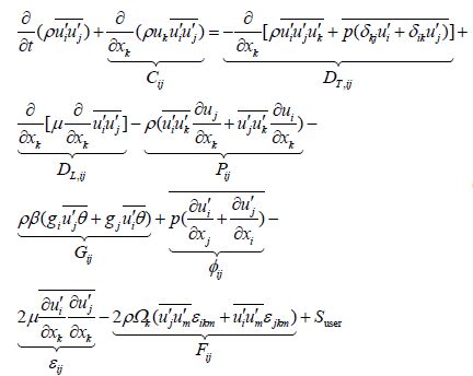
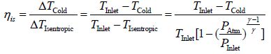
The isentropic efficiency is evaluated by using the equation
|
(10) |
where PAtm, PInlet, TCold, and ΔTIsentropic represent the ambient pressure, the injection pressure, the cold exhaust temperature, and the isentropic temperature drop, respectively. Fig. 8 shows that the highest efficiency is provided with the throttle angle of 60°. Specifically, the efficiency of the convergent VT cyclone separator with α=60° is 32.13% at a cold mass fraction of 0.38, which leads to a 10.7% higher efficiency compared with the basic model (α=30°, Dth=5.5 mm).

|
| Figure 8 Effect of throttle angle of the control valve on the efficiency of convergent air separator |
In the case of the straight vortex tube, Rafiee and Rahimi (2013) stated that the cold temperature drop improves by 45.7% (11.9 ℃) as the nozzle slot number increases from 2 to 6. In other words, the cooling effectiveness increases continuously with an increase in the nozzle number. In the current study, the nozzle number has had a very impressive effect on the cooling performance of the VT cyclone separator with a straight main tube. Fig. 9 shows the variation of cooling effectiveness of the optimum convergent VT cyclone separator with cold mass fraction for different nozzle (slot) numbers. Unlike the conclusion provided by Rafiee and Rahimi (2013) , who examined a straight VT cyclone separator, this research proves that the convergent VT cyclone separator has a different reaction as the slot number increases. As can be seen, the cooling effectiveness improves sharply with an increase in the slot number (up to N=4; the basic model has 4 slots). Then, beyond N=4, the cooling effectiveness decreases (nominal). Moreover, the cooling effectiveness has the lowest values at the minimum slot number N=2. As slot number increases from 2 to 4, the cold temperature difference increases by 28.48%. The physical reason can be explained in this way: when the slot number increases from 2 to 4, the turbulence kinetic energy improves and becomes constant (approximately) beyond four slots. This can be attributed to the fact that the pressure and velocity drop increase as the number of slots increase in the range of 2 to 4, which can then lead to an increase in the cold temperature drop when the slot number also increases from 2 to 4. According to the statements, it can be concluded that, by increasing the slot number, the level of turbulence improves in the convergent VT cyclone separator, which in turn, leads to an increase in the cold temperature drop.

|
| Figure 9 Impact of slot number on cold temperature drop as a function of cold mass fraction |
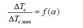
Stephan et al.(1983) conducted an investigation on a similar VT cyclone separator equipped with a straight main tube. Their results show that the ratio of the cold temperature drop to the maximum temperature drop demonstrates a special fraction that varies only with the cold flow fraction as shown by
|
(11) |
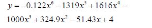
According to Fig. 10, Stephan’s theory is confirmed for the slot numbers. As shown in the figure, the variation of slot number does not change balance of the pressure patterns, so the optimum cold flow fraction also remains unchanged. The similarity relation for the slots number is given by
|
(12) |
Eq.(12) (reported from Fig. 10), indicates that the ratio of $\frac{{\Delta {T_c}}}{{\Delta {T_{c,\max }}}}$ for the convergent VT cyclone separators is independent of the slot number, and can be reported as a single variable parameter, namely, cold flow fraction.

|
| Figure 10 Effects of slot number on non-dimensional cold temperature drop as a function of cold flow fraction |
The current study referred to the results of Stephan et al.(1983) , Farzaneh-Gord et al.(2014) , and Hilsch (1947) to verify the similarity equation for the present convergent VT cyclone separator. The variations of $\frac{{\Delta {T_c}}}{{\Delta {T_{c,\max }}}}$ with the cold flow fraction in four different works are presented in Fig. 11. The results of $\frac{{\Delta {T_c}}}{{\Delta {T_{c,\max }}}}$ for different studies indicate the same trend but with different optimum cold mass fractions. The red lines determine the point of the optimum cold flow fraction for each VT cyclone separator. This difference refers to the dissimilarity of the pressure balance inside the used VT cyclone separators. The structural parameters of the VT cyclone separators in other studies, which are compared with our convergent VT cyclone separator, are presented in Table 6. Fig. 12 shows the effect of injection pressure on cooling effectiveness of convergent vortex tube.
| Methods | Cold exit diameter/mm | Main tube shape | Slotnumber | Main tube length/mm | Shape of the control valve |
| Present work | 9 | Convergent | 4 | 185 | Truncated |
| Hilsch (1947) | 2.6 | Straight | 1 | 300 | cone |
| 6.5 | Straight | 1 | 352 | cone | |
| 7.76-12.28 | Straight | 6 | 95.2 | N/A |
| Cold mass fraction | ΔTcexp | ΔTcnum | Disagreement/% | ΔThexp | ΔThnum | Disagreement/% |
| 0.134 | 20.84 | 19.58 | 5.63 | 11.88 | 11.21 | 6.04 |
| 0.191 | 21.59 | 21.05 | 7.14 | 13.43 | 12.47 | 2.50 |
| 0.28 | 22.87 | 22.57 | 7.14 | 14.98 | 13.91 | 1.31 |
| 0.32 | 22.28 | 22.36 | 8.46 | 16.18 | 14.81 | 0.35 |
| 0.43 | 20.57 | 19.87 | 6.99 | 18.16 | 16.89 | 3.40 |
| 0.488 | 19.98 | 18.85 | 7.77 | 19.43 | 17.92 | 5.65 |
| 0.55 | 18.99 | 18.08 | 6.70 | 20.28 | 18.92 | 4.79 |
| 0.6 | 18.09 | 17.58 | 5.84 | 21.05 | 19.82 | 2.81 |
| 0.66 | 17.35 | 16.67 | 2.65 | 21.48 | 20.91 | 3.91 |
| 0.73 | 16.8 | 15.87 | 2.33 | 22.25 | 21.73 | 5.53 |
| 0.76 | 16.17 | 15.28 | 2.86 | 22.68 | 22.03 | 5.50 |
| 0.81 | 15.73 | 14.37 | 1.59 | 23.24 | 22.87 | 8.64 |
| 0.87 | 14.28 | 13.51 | 1.24 | 23.24 | 22.95 | 5.39 |
| 0.91 | 13.19 | 12.67 | 1.51 | 23.03 | 22.68 | 3.94 |
| 0.93 | 12.58 | 12.34 | 0 | 22.4 | 22.4 | 1.90 |
| 0.96 | 11.11 | 11.29 | 0.22 | 21.97 | 22.02 | 1.62 |

|
| Figure 11 Verification of the similarity relation for the present work and a comparison of the similarity relation for different works (with different optimum cold mass fractions) |

|
| Figure 12 Pressure effect on the cooling performance of convergent air separators |
In the following, the 3D numerical results are validated by comparing the experimental outputs. To validate the computational data, the computed outputs are also compared with the laboratory results gained in the experimental section. Table 7 demonstrates the comparison between the temperature results of the real model (with Dth=5.5 mm and α=30°) and the 3D computation, which used the same geometrical and operating conditions of the real case. The same table shows the temperature differences at the hot and cold exhausts of the convergent VT cyclone system with four nozzle slots, an injection temperature of 294.2 K, and pressure of 0.45 MPa. The comparison between the computed and the laboratory outputs presents favorable agreement, even though some differences exist at certain temperature points.
The average and maximum disagreements between the experimental quantities and the predicted values of the cold temperature difference are 3.71% and 8.64%, respectively. Meanwhile, the average and maximum values regarding the disagreements between the experimental data and the predicted values for the hot temperature difference are 4.23% and 8.46%. These validations indicate that the simulations can generate successful and reliable predictions regarding the laboratory sets. The disagreement between the experimental results and the CFD predictions can be attributed to some assumptions (in this case, the walls of convergent VT cyclone separator are adjusted as an adiabatic boundary condition), which are considered in the simulations.
4.2.2 ContoursOwing to the main objective of this investigation (i.e., to study on the correlation between the flow separation and the energy pattern with different geometrical parameters), it is very important to describe some relevant factors within the convergent VT cyclone separator. The total temperature variations throughout the convergent VT cyclone separator are presented in Fig. 13.

|
| Figure 13 Numerical decryption of fluid flow inside the convergent vortex tubes |
As can be clearly seen, the total temperature of the region close to the walls has a higher value compared with that of the central region. This temperature difference is very apparent at the entrance of the chamber (near the cold orifice) in comparison with other longitudinal areas. The volume of the cold core is constantly growing from the bottom to the top based on the cold exhaust temperature used with different throttle angles (Fig. 13). The use of different throttle angles causes an obvious change in the volume of the cold core. The cold core with a throttle angle of α=60° (Fig. 13 (b) ) is the coldest core and has the highest volume compared with other control valves; this is followed by the cold core with the throttle angle of α=80°. In other words, α=80° is in second place in terms of the highest cold volume and the lowest temperature rankings. The last position belongs to the control valve with α=40°. According to these results, Fig. 13 confirms the results of Figs. 6 and 7 (experimental approach) completely.
In order to provide a clear understanding of the procedures occurring inside the convergent VT cyclone separator, we analyze the flow patterns in these special cases involving the injection pressure equal to 0.45 MPa and the cold flow fraction equal to 0.27, which correspond with the laboratory operating conditions, and give the lowest cold exhaust temperature.
Fig. 14 describes the streamline structures within the developed convergent VT cyclone separators simulated by the RSM turbulence model. These patterns are shown on the longitudinal cross-section of the convergent VT cyclone separators equipped with three different valves (with different throttle angles).

|
| Figure 14 Structural plot of streamlines, vortices, and location of stagnation point for three convergent VT air separators with different throttle angles |
All the models emphasize the creation of some recirculation areas named “vortices” near the chamber (cold exit), which have different sizes and properties. The larger the size of the vortices, the higher the level of mixing between the central cold core and the peripheral layers; thus, the separation capability of the convergent VT cyclone separator decreases with increasing size of the vortices. As seen in Fig. 14, the convergent VT cyclone separator equipped with the valve with α=40° has the lowest cooling efficiency. In relation to such a finding, the flow inside this convergent VT cyclone separator has the highest amount or level of turbulence (turbulent viscosity shown in Fig. 15).

|
| Figure 15 Contour plot of turbulent viscosity for longitudinal sections in comparison form |
Fig. 14 also shows the effect of turbulence level on the location of the stagnation point. The distance between the stagnation point and the control valve is limited by the amount or level of turbulence, and as such, the stagnation point is closer to the valve in α=60°. Thus, the convergent VT cyclone separator with α=60° has the highest cooling ability and the smallest distance between the stagnation point and the hot valve. Meanwhile, the largest distance between that point and the valve belongs to the convergent VT cyclone separator with α=40°, which has the lowest separation efficiency. From the explanations above, it is apparent that cooling capability can be increased by decreasing the distance between the stagnation point and the control valve as much as possible. The two top cases having the smallest distances between the stagnation point and the valve are the convergent VT cyclone separator with α=60° and 80°. These results confirm the findings of Nimbalkar and Muller (2009) , who stated that the stagnation point goes towards the control valve when there is an increase in cooling performance (decrease the cold fraction). Consequently, the convergent VT cyclone separator with α=60° has the best separation process and thermal performance among all the simulated VT cyclone separators.
Compared with molecular viscosity, turbulent viscosity can be considered as the dominant parameter in a highly rotating and fully turbulent flow pattern within the domain of the convergent VT cyclone separator (Thakare et al., 2015). For this reason, turbulent viscosity plays an important role in explaining the extent of turbulence occurring during the energy separation process. Fig. 15 describes the turbulent viscosity contours inside the convergent VTs with different throttle angles. As mentioned previously, the separation process quality is lower when the turbulent viscosity is larger. Specifically, the turbulent viscosity decreased by 12.52% when the throttle angle increases from 40° to 60°; moreover, the turbulent viscosity at α=80° is 6.7% higher than at α=80°. Consequently, for the convergent VT cyclone separators, the smaller level of turbulent viscosity leads to relatively higher separation process quality.
The changes of the rotational velocities for different convergent VT cyclone separators equipped with different control valves (with different throttle angles) are shown in Fig. 16. This figure is presented for different stream-wise sections (Z/L=0.1 and 0.7) along the main tube. As shown in the figure, the rotational or the tangential velocity (along the radius) varies greatly with different throttle angles. The maximum value of the tangential velocity is changed with the stream-wise section and has a downward trend along the length of the hot tube. Hence, it can be stated that the largest possible rotational speeds occurs at the entrance of the main tube (Z/L=0.1) then drops to the lower values as the gas expands along the tube. As previously mentioned, the convergent VT cyclone separator with α=60° exhibits the highest rate of energy separation; moreover, according to the results of Table 8, the highest value of maximum tangential velocity drop belongs to this convergent VT cyclone separator. This finding indicates that the higher the maximum tangential velocity drop, the higher the cooling and separation efficiencies. This also the fact that the high tangential velocity drop and the high temperature difference are the results of the efficient expansion of the gas inside the chamber. Consequently, the VT cyclone separators with α=40° and 80° have the minimum rotational velocity drops as well as the lowest cooling capabilities. Meanwhile, Fig. 17 presents the axial velocity variations on the radial lines in different axial sections. As can be seen, the axial velocity values consist of some positive and negative speed values in each axial section. The cross-section area has been assumed as a velocity domain, in which the velocity of the flow changes from a maximum positive value to a minimum negative magnitude, indicating a reversal pattern for the axial velocity. We can thus say that the gas return process occurs for all the flows inside the VT cyclone separator.

|
| Figure 16 The radial plot for swirl (tangential) velocity |

|
| Figure 17 The radial plot for axial velocity |
| α/ (°) | 40 | 50 | 60 | 70 | 80 |
| ΔV/ (m·s−1) | 135.22 | 150.45 | 164.6 | 156.21 | 143.21 |
Moreover, the difference between the cold core and the flow field pressure creates a drag force that continuously affects how the fluid particles move towards the control valve. The expansion process occurs from the outer to the core layers when the fluid particles cannot resist against the drag force, at which point their velocity reaches zero. During the expansion, the particle temperature decreases sharply, and the fluid particle redirects to the central cold region. The pressure difference acting on the particles creates an accelerating movement which then increases the axial velocity towards the cold exit. As previously mentioned, the convergent VT cyclone separator with α=60° produces the highest cooling and separation capability. According to the results of Fig. 17, the highest values of axial speed at Z/L=0.1 and 0.2 and the minimum values at Z/L=0.7 belong to this convergent VT cyclone separator. Moreover, the VT cyclone separator with α=40° has the minimum axial velocity at Z/L=0.1 and 0.2 and the maximum values at Z/L=0.7, along with the lowest cooling capability. According to Fig. 18, the highest possible pressure values occur at the entrance of the main tube (Z/L=0.1) and then drop to lower values as the gas expands along the tube. The convergent VT cyclone separator with α=60° exhibits the highest energy separation rate.

|
| Figure 18 The radial plot for total pressure |
Moreover, based on the results of Fig. 18 and Table 9, the highest values of the total pressure in the sectional locations (exactly in Z/L=0.1 and approximately in Z/L=0.7) and the maximum total pressure drop belong to this convergent VT cyclone separator. This finding indicates that the higher the total pressure and maximum pressure drop, the higher the cooling and separation efficiencies.
| α/ (°) | 40 | 50 | 60 | 70 | 80 |
| ΔP/kPa | 155.384 | 180.229 | 203.614 | 191.252 | 171.424 |
Laboratory tests and CFD modeling of the convergent VT cyclone separator with different geometrical and operational parameters (throttle angle, injection slot number, and operational pressure) have been carried out. The effects of these parameters on the separation process have been investigated as well. The temperature distributions obtained from the CFD analysis show good agreement with the laboratory results. We also present the results of a series of experimental tests and 3D numerical simulations focused on the optimization of the abovementioned parameters in order to determine which parameter values lead to the best separation, cooling, and heating performances. The internal flow structure and the details of the separation phenomenon, which are affected by these parameters, have also been analyzed. The conclusions are summarized in detail below.
1) When the throttle angle is equal or less than 40°, the hot temperature drop changes gradually, whereas the hot temperature drop changes rapidly when the throttle angle is larger than 40°. Applying the convergent VT air separator with α=60° leads to a 50.60% (11.8 ℃) higher hot temperature drop at the cold mass fraction of 0.75, as compared with α=30°. Moreover, the convergent VT air separator equipped with a throttle valve with α=60° provides a 43.76% higher cold temperature drop and 50.60% higher hot temperature drop compared with the basic model (α=30° and Dth=5.5 mm).
2) The cooling effectiveness improves sharply with an increase in the slot number of up to N=4, beyond which the cooling effectiveness decreases (nominal). The cooling effectiveness has the lowest values at the minimum slot number N=2. As slot number increases from 2 to 4, the cold temperature difference also increases by 28.48%.
3) The results indicate that the ratio of $\frac{{\Delta {T_c}}}{{\Delta {T_{c,\max }}}}$ for the convergent VT cyclone separators is independent of the slot number, and can be reported as only a single variable parameter called “cold flow fraction.”
4) The average and the maximum disagreements between the experimental quantities and the predicted values of the cold temperature difference are 3.71% and 8.64%, respectively. Meanwhile, the average and the maximum values concerning the disagreements between the experimental data and the predicted values for the hot temperature difference are 4.23% and 8.46%, respectively. These validations indicate that the simulations can generate successful and reliable predictions using the laboratory sets.
5) For the convergent VT cyclone separators, a smaller level of turbulent viscosity leads to a relatively greater separation process quality or the generation of smaller vortices near the chamber.
6) Finally, the highest values of maximum tangential velocity and total pressure drops correspond to α=60°, indicating that the higher the maximum tangential velocity and pressure drops, the higher the cooling and separation efficiencies.
| Agrawal N, Naik SS, Gawale YP, 2014. Experimental investigation of vortex tube using natural substances. International Communications in Heat and Mass Transfer, 52, 51–55. DOI:10.1016/j.icheatmasstransfer.2014.01.009 |
| Ahlborn BK, Gordon JM, 2000. The vortex tube as a classic thermodynamic refrigeration cycle. Journal of Applied Physics, 88(6), 3645–3653. DOI:10.1063/1.1289524 |
| Akhesmeh S, Pourmahmoud N, Sedgi H, 2008. Numerical study of the temperature separation in the Ranque–Hilsch vortex tube. American Journal of Engineering and Applied Sciences, 1(3), 181–187. DOI:10.3844/ajeassp.2008.181.187 |
| Alekhin V, Bianco V, Khait A, Noskov A, 2015. Numerical investigation of a double-circuit Ranque–Hilsch vortex tube. International Journal of Thermal Sciences, 89, 272–282. DOI:10.1016/j.ijthermalsci.2014.11.012 |
| Aljuwayhel NF, Nellis GF, Klein SA, 2005. Parametric and internal study of the vortex tube using a CFD model. Int J Refrigeration, 28(3), 442–450. DOI:10.1016/j.ijrefrig.2004.04.004 |
| Avci M, 2013. The effects of nozzle aspect ratio and nozzle number on the performance of the Ranque–Hilsch vortex tube. Applied Thermal Engineering, 50(1), 302–308. DOI:10.1016/j.applthermaleng.2012.06.048 |
| Aydin O, Baki M, 2006. An experimental study on the design parameters of a counter flow vortex tube. Energy, 31(14), 2763–2772. DOI:10.1016/j.energy.2005.11.017 |
| Baghdad M, Ouadha A, Imine O, Addad Y, 2011. Numerical study of energy separation in a vortex tube with different RANS models. Int. J. Thermal Sciences, 50(12), 2377–2385. DOI:10.1016/j.ijthermalsci.2011.07.011 |
| Bej N, Sinhamahapatra KP, 2014. Energy analysis of a hot cascade type Ranque–Hilsch vortex tube using turbulence model. International Journal of Refrigeration, 45, 13–24. DOI:10.1016/j.ijrefrig.2014.05.020 |
| Berber A, Dincer K, Yılmaz Y, Ozen DN, 2013. Rule-based Mamdani-type fuzzy modeling of heating and cooling performances of counter-flow Ranque–Hilsch vortex tubes with different geometric construction for steel. Energy, 51, 297–304. DOI:10.1016/j.energy.2013.01.005 |
| Bovand M, Valipour MS, Dincer K, Tamayol A, 2014a. Numerical analysis of the curvature effects on Ranque–Hilsch vortex tube refrigerators. Applied Thermal Engineering, 65(1-2), 176–183. DOI:10.1016/j.applthermaleng.2013.11.045 |
| Bovand M, Valipour MS, Eiamsa-ard S, Tamayol A, 2014b. Numerical analysis for curved vortex tube optimization. International Communications in Heat and Mass Transfer, 50, 98–107. DOI:10.1016/j.icheatmasstransfer.2013.11.012 |
| Chang K, Li Q, Zhou G, Li Q, 2011. Experimental investigation of vortex tube refrigerator with a divergent hot tube. International Journal of Refrigeration, 34(1), 322–327. DOI:10.1016/j.ijrefrig.2010.09.001 |
| Dincer K, 2011. Experimental investigation of the effects of threefold type Ranque–Hilsch vortex tube and six cascade type Ranque–Hilsch vortex tube on the performance of counter flow Ranque–Hilsch vortex tubes. International Journal of Refrigeration, 34(6), 1366–1371. DOI:10.1016/j.ijrefrig.2011.05.008 |
| Dincer K, Baskaya S, Uysal BZ, 2008. Experimental investigation of the effects of length to diameter ratio and nozzle number on the performance of counter flow RanqueeHilsch vortex tubes. Heat Mass Transfer, 44(3), 367–373. DOI:10.1007/s00231-007-0241-z |
| Dutta T, Sinhamahapatra KP, Bandyopadhyay SS, 2011. Numerical investigation of gas species and energy separation in the Ranque–Hilsch vortex tube using real gas model. International Journal of Refrigeration, 26(8), 2118–2128. DOI:10.1016/j.ijrefrig.2011.06.004 |
| Farzaneh-Gord M, Sadi M, 2014. Improving vortex tube performance based on vortex generator design. Energy, 72, 492–500. DOI:10.1016/j.energy.2014.05.071 |
| Gutak AD, 2015. Experimental investigation and industrial application of Ranque–Hilsch vortex tube. International Journal of Refrigeration, 49, 93–98. DOI:10.1016/j.ijrefrig.2014.09.021 |
| Han X, Li N, Wu K, Wang Z, Tang L, Chen G, Xu X, 2013. The influence of working gas characteristics on energy separation of vortex tube. Applied Thermal Engineering, 61(2), 171–177. DOI:10.1016/j.applthermaleng.2013.07.027 |
| Hilsch R, 1947. The use of expansion of gases in a centrifugal field as a cooling process. Rev. Sci. Instrum, 18, 108–113. DOI:10.1063/1.1740893 |
| Im SY, Yu SS, 2012. Effects of geometric parameters on the separated air flow temperature of a vortex tube for design optimization. Energy, 37(1), 154–160. DOI:10.1016/j.energy.2011.09.008 |
| Kandil HA, Abdelghany ST, 2015. Computational investigation of different effects on the performance of the Ranque–Hilsch vortex tube. Energy, 84, 207–218. DOI:10.1016/j.energy.2015.02.089 |
| Khait AV, Noskov AS, Lovtsov AV, Alekhin VN, 2014. Semi-empirical turbulence model for numerical simulation of swirled compressible flows observed in Ranque–Hilsch vortex tube. International Journal of Refrigeration, 48, 132–141. DOI:10.1016/j.ijrefrig.2014.09.006 |
| Khazaei H, Teymourtash AR, Malek-Jafarian M, 2012. Effects of gas properties and geometrical parameters on performance of a vortex tube. Scientia Iranica, 19(3), 454–462. DOI:10.1016/j.scient.2012.03.003 |
| Korkmaz ME, Gümüşel L, Markal B, 2012. Using artificial neural network for predicting performance of the Ranque–Hilsch vortex tube. International Journal of Refrigeration, 35(6), 1690–1696. DOI:10.1016/j.ijrefrig.2012.04.013 |
| Kulyk M, Lastivka I, Tereshchenko Y, 2012. Effect of hysteresis in axial compressors of gas-turbine engines,. Aviation, 16(4), 97–102. DOI:10.3846/16487788.2012.753679 |
| Li N, Zeng ZY, Wang Z, Han XH, Chen GM, 2015. Experimental study of the energy separation in a vortex tube. International Journal of Refrigeration, 55, 93–101. DOI:10.1016/j.ijrefrig.2015.03.011 |
| Liu X, Liu Z, 2014. Investigation of the energy separation effect and flow mechanism inside a vortex tube. Applied Thermal Engineering, 67(1-2), 494–506. DOI:10.1016/j.applthermaleng.2014.03.071 |
| Moffat RJ, 1985. Using uncertainty analysis in the planning of an experiment. Trans. ASME, J. Fluids Eng., 107(2), 173–178. DOI:10.1115/1.3242452 |
| Mohammadi S, Farhadi F, 2013. Experimental analysis of a Ranque–Hilsch vortex tube for optimizing nozzle numbers and diameter. Applied Thermal Engineering, 61(2), 500–506. DOI:10.1016/j.applthermaleng.2013.07.043 |
| Mohammadi S, Farhadi F, 2014. Experimental and numerical study of the gas–gas separation efficiency in a Ranque–Hilsch vortex tube. Separation and Purification Technology, 138(10), 177–185. DOI:10.1016/j.seppur.2014.10.022 |
| Nimbalkar SU, Muller MR, 2009. An experimental investigation of the optimum geometry for the cold end orifice of a vortex tube. Appl Therm Eng, 29(2–3), 509–514. DOI:10.1016/j.applthermaleng.2008.03.032 |
| Ouadha, A ., Baghdad, M ., Addad, Y ., 2013. “Effects of variable thermophysical properties on flow and energy separation in a vortex tube. International Journal of Refrigeration, 36(8), 2426–2437. DOI:10.1016/j.ijrefrig.2013.07.018 |
| Pinar AM, Uluer O, Kırmaci V, 2009. Optimization of counter flow Ranque–Hilsch vortex tube performance using Taguchi method. International Journal of Refrigeration, 32, 1487–1494. DOI:10.1016/j.ijrefrig.2009.02.018 |
| Piralishvili SA, Polyaev VM, 1996. Flow and thermodynamic characteristics of energy separation in a double-circuit vortex tube–an experimental investigation. Experimental Thermal and Fluid Science, 12(4), 399–410. DOI:10.1016/0894-1777(95)00122-0 |
| Pourmahmoud N, Hassanzadeh A, Moutaby O, 2012a. Numerical analysis of the effect of helical nozzles gap on the cooling capacity of Ranque–Hilsch vortex tube. International Journal of Refrigeration, 35(5), 1473–1483. DOI:10.1016/j.ijrefrig.2012.03.019 |
| Pourmahmoud N, Hassanzadeh A, Rafiee SE, Rahimi M, 2012b. Three-dimensional numerical investigation of effect of convergent nozzles on the energy separation in a vortex tube. International Journal of Heat and Technology, 30(2), 133–140. DOI:10.18280/ijht |
| Pourmahmoud N, Rafiee SE, Rahimi M, Hassanzadeh A, 2013. Numerical energy separation analysis on the commercial Ranque-Hilsch vortex tube on basis of application of different gases. Scientia Iranica, 20(5), 1528–1537. |
| Pourmahmoud N, Rahimi M, Rafiee SE, Hassanzadeh A, 2014. A numerical simulation of the effect of inlet gas temperature on the energy separation in a vortex tube. Journal of Engineering Science and Technology, 9(1), 81–96. |
| Rafiee SE, Ayenehpour S, Sadeghiazad MM, 2016. A study on the optimization of the angle of curvature for a Ranque–Hilsch vortex tube, using both experimental and full Reynolds stress turbulence numerical modeling. Heat and Mass Transfer, 52(2), 337–350. DOI:10.1007/s00231-015-1562-y |
| Rafiee SE, Rahimi M, 2013. Experimental study and three-dimensional (3D) computational fluid dynamics (CFD) analysis on the effect of the convergence ratio, pressure inlet and number of nozzle intake on vortex tube performance-Validation and CFD optimization. Energy, 63, 195–204. DOI:10.1016/j.energy.2013.09.060 |
| Rafiee SE, Rahimi M, 2014. Three-dimensional simulation of fluid flow and energy separation inside a vortex tube. Journal of Thermophysics and Heat Transfer, 28(1), 87–99. DOI:10.2514/1.T4198 |
| Rafiee SE, Rahimi M, Pourmahmoud N, 2013. Three-dimensional numerical investigation on a commercial vortex tube based on an experimental model-Part I: Optimization of the working tube radius. International Journal of Heat and Technology, 31(1), 49–56. |
| Rafiee SE, Sadeghiazad MM., 2014. Three-dimensional and experimental investigation on the effect of cone length of throttle valve on thermal performance of a vortex tube using k–ε turbulence model. Applied Thermal Engineering, 66(1-2), 65–74. DOI:10.1016/j.applthermaleng.2014.01.073 |
| Rafiee SE, Sadeghiazad MM, 2014b. 3D cfd exergy analysis of the performance of a counter flow vortex tube. International Journal of Heat and Technology, 32(1-2), 71–77. |
| Rafiee SE, Sadeghiazad MM, 2014c. Effect of conical valve angle on cold-exit temperature of vortex tube. Journal of Thermophysics and Heat Transfer, 28(4), 785–794. DOI:10.2514/1.T4376 |
| Rafiee SE, Sadeghiazad MM, 2015. 3D numerical analysis on the effect of rounding off edge radius on thermal separation inside a vortex tube. International Journal of Heat and Technology, 33(1), 83–90. DOI:10.18280/ijht |
| Rafiee SE, Sadeghiazad MM, 2016a. Three-dimensional numerical investigation of the separation process in a vortex tube at different operating conditions. Journal of Marine Science and Application, 15(2), 157–165. DOI:10.1007/s11804-016-1348-8 |
| Rafiee SE, Sadeghiazad MM, 2016b. Three-dimensional computational prediction of vortex separation phenomenon inside the Ranque–Hilsch vortex tube. Aviation, 20(1), 21–31. DOI:10.3846/16487788.2016.1139814 |
| Rafiee SE, Sadeghiazad MM, 2016c. Heat and mass transfer between cold and hot vortex cores inside Ranque-Hilsch vortex tube-optimization of hot tube length. International Journal of Heat and Technology, 34(1), 31–38. DOI:10.18280/ijht.340105 |
| Rafiee SE, Sadeghiazad MM, 2016d. Three-dimensional CFD simulation of fluid flow inside a vortex tube on basis of an experimental model-The optimization of vortex chamber radius. International Journal of Heat and Technology, 34(2), 236–244. DOI:10.18280/ijht.340212 |
| Rafiee SE, Sadeghiazad MM, 2016e. Experimental and 3D-CFD study on optimization of control valve diameter for a convergent vortex tube. Frontiers in Heat and Mass Transfer, 7(1), 1–15. DOI:10.5098/hmt.7.13 |
| Rafiee SE, Sadeghiazad MM, 2017. Experimental and 3D CFD investigation on heat transfer and energy separation inside a counter flow vortex tube using different shapes of hot control valves. Applied Thermal Engineering, 110, 648–664. DOI:10.1016/j.applthermaleng.2016.08.166 |
| Rafiee SE, Sadeghiazad MM, Mostafavinia N, 2015. Experimental and numerical investigation on effect of convergent angle and cold orifice diameter on thermal performance of convergent vortex tube. Journal of Thermal Science and Engineering Applications, 7(4), 041006. DOI:10.1115/1.4030639 |
| Rahimi M, Rafiee SE, Pourmahmoud N, 2013. Numerical investigation of the effect of divergent hot tube on the energy separation in a vortex tube. International Journal of Heat and Technology, 31(2), 17–26. DOI:10.18280/ijht |
| Ranque GJ, 1933. Experiments on expansion in a vortex with simultaneous exhaust of hot air and cold air. Le J. de Physique et le Radium, 4, 112–114. |
| Saidi MH, Allaf Yazdi MR, 1999. Energy model of a vortex tube system with experimental results. Energy, 24, 625–632. DOI:10.1016/S0360-5442(98)00076-0 |
| Sadi M, Farzaneh-Gord M, 2014. Introduction of annular vortex tube and experimental comparison with ranque–hilsch vortex tube. International Journal of Refrigeration, 46, 142–151. DOI:10.1016/j.ijrefrig.2014.07.004 |
| Saidi MH, Valipour MS, 2003. Experimental modeling of vortex tube refrigerator. Applied Thermal Engineering, 23(15), 1971–1980. DOI:10.1016/S1359-4311(03)00146-7 |
| Secchiaroli A, Ricci R, Montelpare S, D’Alessandro V, 2009. Numerical simulation of turbulent flow in a RanqueeHilsch vortex tube. International Journal of Heat and Mass Transfer, 52(23-24), 5496–5511. DOI:10.1016/j.ijheatmasstransfer.2009.05.031 |
| Shamsoddini R, Hossein Nezhad A, 2010. Numerical analysis of the effects of nozzles number on the flow and power of cooling of a vortex tube. International Journal of Refrigeration, 33(4), 774–782. DOI:10.1016/j.ijrefrig.2009.12.029 |
| Skye HM, Nellis GF, Klein SA, 2006. Comparison of CFD analysis to empirical data in a commercial vortex tube. International Journal of Refrigeration, 29(1), 71–80. DOI:10.1016/j.ijrefrig.2005.05.004 |
| Stephan K, Lin S, Durst M, Seher F, Huang D, 1983. An investigation of energy separation in a vortex tube. International Journal of Heat and Mass Transfer, 26(3), 341–348. DOI:10.1016/0017-9310(83)90038-8 |
| Subudhi S, Sen M, 2015. Review of Ranque–Hilsch vortex tube experiments using air. Renewable and Sustainable Energy Reviews, 52, 172–178. DOI:10.1016/j.rser.2015.07.103 |
| Thakare HR, Monde A, Parekh AD, 2015. Experimental, computational and optimization studies of temperature separation and flow physics of vortex tube: A review. Renewable and Sustainable Energy Reviews, 52, 1043–1071. DOI:10.1016/j.rser.2015.07.198 |
| Thakare HR, Parekh AD, 2015. Computational analysis of energy separation in counter—flow vortex tube. Energy, 85, 62–77. DOI:10.1016/j.energy.2015.03.058 |
| Valipour MS, Niazi N, 2011. Experimental modeling of a curved Ranque–Hilsch vortex tube refrigerator. International Journal of Refrigeration, 34(4), 1109–1116. DOI:10.1016/j.ijrefrig.2011.02.013 |