


 , ,
, ,
2. SubSea R&D Center, Isfahan University of Technology, Isfahan P.O. Box 84156, Iran
1 Introduction
Owing to population growth and urban development next to the seas, it is necessary to design and construct offshore and coastal structures. All coastal and offshore structures such as sea walls, breakwaters, and oil platforms are affected by wave action directly or indirectly. The hydraulic characteristics of breakwaters have been investigated by many researchers by using various types of wave absorbers. For wave absorbers, low values of the reflection coefficient, Cr (defined as the ratio of reflected wave height to incident wave height) and transmission coefficient, Ct (defined as the ratio of transmitted wave height to incident wave height) are desirable. Lean (1967) presented an analysis based on the linear long wave theory to determine theCr of permeable wave absorbers of basic shapes. In addition, he carried out experiments on absorbers with vertical-wall, uniformly sloped, and parabolic shape profiles. He concluded that the parabolic profile can be employed to reduce absorber length. To attain Cr<0.1, Lean recommended that the length of a wave absorber (l) should be about 0.5L to 0.75L, where L is the incident wavelength.
Le Méhauté (1972) presented a progressive wave absorber that dissipates the incident wave energy gradually. In each section of the progressive wave absorber, a portion of the wave energy is dissipated, and the remaining wave energy is reflected or transmitted. He performed a few experiments on a 1 m long wave absorber composed of 10 mm chicken wire mesh installed vertically in the middle of a towing tank. For wavelength L=1 080 mm, wave period T=1 s, water depth of d=150 mm, and wave height of H=40 mm, the reflection coefficient for a specific cell position was Cr≈ 0.02.
Ouellet and Datta (1986) conducted a literature review by sending a questionnaire to 162 hydraulic and ship model tanks to survey the facilities and wave absorber systems. The target of the study was to determine the optimum wave absorber and to make recommendations for future research. They showed that for a specific slope, the reflection coefficient of impermeable plane-sloped wave absorbers decreased with increasing wave steepness (ratio of wave height to wave length=H/L). In addition, they showed that for slope angle <15°, the variation of reflection coefficient against wave absorber slope is similar for stone crushed rocks and wire meshes. The parabolic profile was recommended as the most efficient wave absorber shape.
Jamieson and Mansard (1987) conducted experiments to obtain an efficient wave absorber comprising multi-wire mesh screens, with plate porosity decreasing in the direction of wave incidence. The screens were placed normal to the direction of wave propagation. They showed that the screens with the highest porosities (located upstream) and those with the lowest porosities were more efficient for high and low wave steepness values, respectively. The optimum wave absorber length was found to be 0.35L-1.0L, where L is the maximum wavelength. They recommended the adoption of wider spacing between plates for waves with high wave steepness values and long wave periods.
Lu and He (1989) investigated the reflection and transmission characteristics of a thin curved permeable plate by using the panel method for small wave amplitude to wavelength ratios. The equations of the curved plates were y=−x2 and y=−0.5x2. The results are presented in the form of variation of Cr2 against ν=$\varpi $2/g for different values of ρb/μ, where $\varpi $ is angular frequency, g gravitational acceleration, b material constant, and ρ & μ fluid density and dynamic viscosity, respectively. The results show that for ρb/μ= 0.25, the incident wave energy in the range of 0.6<n<4 is absorbed almost completely. Moreover, they concluded that the reflection coefficients of the two curved plates are almost equal.
Chegini (1993) used a permeable sloping wave absorber covered by a layer of horse hair material and performed a series of laboratory tests in a towing tank. The wave absorber was tested at three slopes of 10%, 15%, and 20%. The results show that for a specific slope, reflection coefficient decreased as wave steepness increased. For wave steepness values ranging from 0.01 to 0.1, the reflection coefficientfor the 10% slope was less than that for the 6% slope. In addition, the results show relative water depths (water depth to wavelength ratio) of 0.124-0.4 had no significant effect on the reflection coefficient.
Chegini (1995) studied experimentally the reflection and transmission of vertical perforated plates of various porosities and wave steepness values. He used two types of perforated plates: general perforated plates with 23%, 40%, and 62% porosities and expanded metal plates with 26%, 42%, and 58% porosities. Tests were performed with water depth of 0.8 m and wave steepness values of 0.003-0.01. The results show that Cr increased with increasing wave steepness.
Wu et al.(1998) numerically investigated the reflection coefficient of a wave absorber system, including an end wall and a horizontal submerged porous plate. The numerical results indicate that the reflection coefficient decreased with increasing porosity. With increasing relative water depth, Cr first decreases and then increases for a specific porosity.
Twu and Chieu (2000) developed an offshore breakwater with low values of both Cr and Ct. The proposed breakwater includes n layers of porous materials of different porosities. The gentle slope at the end of the flume was covered with sand as a wave absorber. They performed experiments to verify theoretical computations, with wave periods of 0.3-1.5 s and wave heights of up to 150 mm. The results show that Cr first increases as the spacing between the porous plates is increased and then oscillates around a constant value. The results also indicate that with increasing spacing between porous plates, wave transmission coefficient decreases gradually. The wave reflection coefficient also increases with decreasing porosity, whereas increases in porosity and spacing between porous plates have no significant effects on both the reflection and the transmission coefficients.
Liu et al.(2007) numerically investigated the reflection coefficientof a wave absorber consisting of an end wall, a vertical perforated wall, and a horizontal perforated plate between them. The horizontal perforated plate increased absorber stability and absorption capacity. The results show that with increasing relative water depth, Cr first increases and then decreases. Absorber performance was found to improve when the horizontal porous plate was placed close to the water surface. They concluded that for practical engineering applications, the vertical perforated plate porosity should be 20%-40%.
Rostaminia and Chegini (2008) studied the wave reflection and transmission coefficients of a single perforated flat plate installed at angles of 60°, 75°, and 90° (with respect to the horizontal) and having porosities of 21%, 44%, and 48%. A wave sloped screen parameter was introduced to describe the hydraulic performance of the aforementioned sloped perforated sheets. Laboratory tests were performed in a wave flume measuring 32.5 m in length, 5.5 m in width, and 1 m in depth. The water depth was set to 0.5 m. Regular waves were generated under the intermediate condition with periods of 1.25-2.5 s and wave heights of 76-184 mm. The results show that by increasing the sloped screen parameter, Cr decreases and Ct increases. The reflection coefficient increased, whereas Ctdecreased, with increasing incident wave steepness.
Owing to the limited number of experimental studies on curved-type wave absorbers and considering the recommendation of Ouellet and Datta (1986) , we experimentally study parabolic perforated plates (curved barriers). The aim of this study is determining the reflection coefficient of a curved barrier for regular waves. The effects of the curvature of a porous plate on the reflection coefficient are examined and the results are compared with those of vertical and sloped barriers. The curve characteristics (wave height and wavelength versus wave frequency) of plunger-type wave makers, used in the experiments, were obtained. Experiments are conducted on a curved model given by the equation of y=−x2. The model is then tested for various rotation angles (with respect to the horizontal axis) and submerged depths (su). Goda and Suzuki’ (1976) method is used to decompose a partial standing wave in front of the model. The experiments are performed with non-breaking regular waves under the deepwater condition.
2 Experimental setupThe experiments were carried out in a 108 m long, 3 m wide, and 2.50 m deep towing tank located in the Subsea R&D Center at Isfahan University of Technology, Isfahan, Iran (Fig. 1). The sidewalls of the wave tank are made of concrete, with three underwater observation windows. The tank is equipped with a mechanical-electrical plunger-type wave maker. It generates regular waves with a wide range of wave periods and wave heights. Wave frequencies of 0.65-0.93 Hz and a wave height of 130 mm were used in our experiments. Upward and downward plunger movement was controlled by a potentiometer control box. All tests were carried out at a water depth of 2.23 m. Resistive-type wave probes and transducers were used for wave profile measurement. Two probes upstream of the screen were used to record the composite wave profile and another one located downstream of the wave maker was used to measure the incident wave.

|
| Figure 1 Schematic of experimental setup |
Instead of using an inclined bottom at the end of the tank to minimize the reflection effects of the back wall on the model, a progressive wave absorber consisting of five porous plates with different porosities, decreasing in the direction of incident wave, was placed at the downstream end of the wave tank. The progressive wave absorber had three degrees of freedom, namely, change in submerged depth, change in angle of porous plate with respect to the tank’s longitudinal direction, and change in the frame angle around the plates. The reflection coefficient of the absorber was less than 8%.
A software application and an A/D converter developed in this study were used to record water surface profiles with different sampling rates and to transfer the recorded data to a computer. The software sampled data at 0.02 s intervals (sampling frequency=50 Hz). The time series, collected by two wave probes upstream of the model, were analyzed by Goda and Suzuki’s (1976) method to decompose incident and reflected waves in front of the model and to calculate the reflection coefficient. Wave probe spacing (∆l) and distance between the nearest probe and the reflective model (x1) were identified as the parameters of this method. According to Goda and Suzuki’ (1976) recommendation, x1 and ∆l were set to about 1.06 m and 410 mm, respectively. One of the probes was positioned 18 m downstream of the wave maker to measure the regular incident wave profile in order to obtain the characteristics of the plunger wave maker. The curve characteristics of the plunger wave maker are shown in Fig. 2, where f, L, and H are wave frequency (Hz), wavelength (m), and wave height (mm), respectively. Fig. 2 shows that by increasing the wave frequency, wave height and wavelength increases and decreases, respectively. When the probe detects stable regular waves, data sampling is commenced and it continues before re-reflected waves from the wave maker start affecting the reflection coefficient measurements. Wave parameters are obtained by analyzing the regular signal.

|
| Figure 2 Curve characteristics of plunger wave maker |
The base model was a rectangular galvanized perforated plate measuring 1 mm in thickness, with staggered circular holes measuring 10 mm in diameter, and having a porosity of about 42%. The plate had a parabolic profile of y=−x2, which is the base model in this research. The base model was rotated clockwise (5° and 10°) and counterclockwise (5°, 10°, 15°, 20°, 25°, and 35°) to reproduce different profiles with different equations. Here, counterclockwise rotation is the positive conventional direction, while clockwise rotation is the negative conventional direction. The base model denoted by T0 represents y=−x2 rotated by 0°. Other models such as -T10 and T10 represent 10° rotation of the base model (y=−x2) in the clockwise and the counterclockwise directions, respectively. All models were tested at a submerged depth su=0.24 m. Three models, namely, -T10, T0, and T25, were also tested at a submerged depth of 0.12 m, while models T25 and T0 were also tested at a submerged depth of 0.36 m. The models were located 50 m from the start of the tank (Fig. 1 (b) ). Horizontal (l) and vertical (h) projection lengths of the base model were set at 690 mm and 480 mm, respectively (Fig. 3). Meanwhile, the convex part of each curved profile faced the wave direction.

|
| Figure 3 Schematic diagram of base model at submerged depth su=0.24 m |
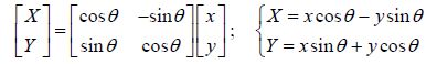
The rotation angle and the associated horizontal and vertical projection lengths of the model were adjusted by a structure mounted on the rails along the sidewalls of the tank. Profile equations of different models were obtained based on the coordinates shown in Fig. 3. To set the location of each curved profile, the curved model was shifted upward and downward to adjust arbitrary submerged depths and angles of rotation with respect to the coordinate system. Counterclockwise rotation matrices were used to generate new coordinates resulting from rotation of the base model as follows:
|
(1) |
where X and Y are the rotated coordinates and θ is the rotation angle at the origin with respect to the reference profile. The equation of any curved model is expressed as follows:
|
(2) |
where a, b, and c are coefficients and are listed in Table 1. Fig. 4 shows the profiles of a few models.

|
| Figure 4 Geometry of a few models tested in the tank |
For a constant submerged depth, counterclockwise rotation of the base model increases the vertical projection length (h) of the models. For clockwise rotation, this value decreases (Fig. 4). By determining the equation of the parabolic profile, the vertical projection length was obtained as one of the characteristics of the parabolic profile.
| Model | a | b | c | su/mm | h/mm | l/mm |
| −T10 | −0.741 | −0.099 | −0.103 | 120 | 355 | 762 |
| −0.128 | 240 | |||||
| −T5 | −0.848 | −0.045 | −0.064 | 240 | 418 | 729 |
| T0 | −1 | 0 | 0 | 240 | 480 | 690 |
| 0.116 | 120 | |||||
| −0.123 | 360 | |||||
| T5 | −1.218 | 0.034 | 0.0529 | 240 | 530 | 646 |
| T10 | −1.54 | 0.0517 | 0.105 | 240 | 580 | 597 |
| T15 | −2.031 | 0.041 | 0.152 | 240 | 622 | 543 |
| T20 | −2.814 | −0.015 | 0.193 | 240 | 656 | 486 |
| T25 | −4.136 | −0.154 | 0.227 | 240 | 679 | 424 |
| 0.347 | 120 | |||||
| 0.107 | 360 | |||||
| T35 | −11 | −0.955 | 0.277 | 240 | 660 | 292 |
Reflection coefficients of non-breaking regular waves were measured as a function of wave steepness defined as s=Hi/L (where Hi is the incident wave height). In this study, s was varied from 0.016 to 0.068. The wave periods used in the experiments were 1.08, 1.17, 1.26, 1.38, and 1.52 s. All experiments were carried out under the deepwater condition (water depth d≈2.23 m). The wavelength in the deepwater condition (Lo) was calculated as follows:
|
(3) |
In this study, so represents deepwater wave steepness. Fig. 5 shows the variation of the reflection coefficients of all models (clockwise and counterclockwise rotation) at a submerged depth of 240 mm against wave steepness. By increasing the wave steepness parameter in all models, the reflection coefficient increased. In this figure, is shown that the data scatter of wave steepness ranges between 0.015 and 0.028. In this wave steepness range, the reflection coefficients of the counterclockwise rotated models are lower than those of the clockwise rotated models. It seems that the shape of the curved porous plate affects the reflection coefficient for lower wave steepness values.

|
| Figure 5 Reflection coefficient of models versus wave steepness for su = 240 mm |
The variation of reflection coefficient with submergence depth parameter is shown in Fig. 6 as well. In this figure, with an increase in wave steepness (different wave steepness values) at all submergence depths, the reflection coefficient increases. The results shown in this figure represent different models with different orientations for each value of wave steepness. An increase in the submergence depth parameter led to a decrease in the models’ angle of rotation from T25 to -T10 in the clockwise direction. It is evident that increasing the submergence depth to values greater than su/h= 0.45 (in some cases greater than su/h=0.41) has no effect on the reflection coefficient in terms of variation, and the aforementioned value yielded an approximately constant reflection coefficient value. In fact, changing the rotation from T10 or T5 in the clockwise direction causes no significant variation in the reflection coefficient. In addition, in lower submergence depth ranges, the model shape influences the reflection coefficient.

|
| Figure 6 Variation of reflection coefficient versus submergence depth at su=0.24m |
The results obtained in the present work were compared with those of Rostaminia and Chegini (2008) . The maximum value of the reflection coefficient in the present study is 15.3% (Fig. 5). Although the experimental setups used in the two aforementioned studies are not identical, the reflection coefficient of the curved plates in the present work (porosity=42%) is lower than the corresponding values of flat plates in the previous work (porosity=44%) over the same wave steepness range. As shown in Fig. 7, for the perforated plate with 44% porosity and all inclination angles of the perforated plate in the flume, the average value of the reflection coefficient is ~26%, while in present study, this value for curved porous plates at su=0.24 m is ~9%. This shows that parabolic profiles can reduce the reflection coefficient significantly, as emphasized by Ouellet and Datta (1986) .

|
| Figure 7 Comparison of reflection coefficient obtained by Rostaminia and Chegini (2008) with that obtained in the present work |
Furthermore, the experimental results obtained herein were compared with those obtained by Chuan-Jing and Sheng (1989) , who presented numerical results in terms of the variation of Cr2 (percentage of reflected energy) versus ν ($\varpi $2/g) for different values of rb/m. As shown in Fig. 8, for all models used in this study (rotation angles of 25°-66°), the results of experiments conducted at a submerged depth of 0.24 m are in good agreement with the results of Jing and Sheng, especially at high frequencies in the range of 1.74<ν<3.46. Notably, the calculation of rb/m is not the main goal in this comparison. In fact, Fig. 8 represents the similarity in Cr2 versus ν values in both studies. In addition, they concluded that by decreasing in inclination of the models (y=−x2 and y=−0.5x2), the trapping ability of curved model does not improve.
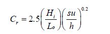
The experimental results show that the reflection coefficient of a perforated plate is a function of deep water steepness (Hi/Lo) and relative submergence depth (su/h). Using the experimental data, the best fit is presented as follows:
|
(4) |
Variation of the reflection coefficient is shown in Fig. 9. By using the deepwater wave parameters, the plot in Fig. 9 can be used to calculate the reflection coefficient of any curved perforated plate, provided that reflection coefficient is located in the range considered in this study.

|
| Figure 8 Comparison of the reflected energy of Jing and Sheng (1989) with the present work |

|
| Figure 9 Variation of experimental reflection coefficient versus calculated reflection coefficient, Cr |
Reflection coefficients of various curved perforated plates were investigated. The base model (T0) consisted of a parabolic perforated plate (y=−x2) rotated in the clockwise and the counterclockwise directions to obtain different models. For lower ranges of wave steepness and submergence depth, the reflection coefficient followed the shape of the curved model. Meanwhile, upon increasing the submergence depth to beyond 0.41 or 0.45 while keeping the wave steepness constant, there was no significant variation in the reflection coefficient. In fact, it cannot be expressed that which specified model has minimum reflection coefficient. It is shown that a curved screen profile could be more efficient than an upright or inclined (flat) porous plate. An empirical formula to estimate the reflection coefficient of the curved plate is introduced.
AcknowledgementThe authors greatly appreciate Prof. Yoshimi Goda for helpful advice. We would also like to thank the Subsea R&D Center, Isfahan University of Technology. The authors are grateful to Dr. Vahid Chegini for his constructive comments.
| Chegini V, 1993. Experimental study of a permeable sloping wave absorber. Research Report, No. 184, The University of New South Wales, Sydney. |
| Chegini V, 1995. Design of upright perforated energy dissipaters for use in wave basins. PhD thesis, School of Civil Engineering, University of New South Wales, Sydney, Australia. |
| Goda Y, Suzuki Y, 1976. Estimation of incident and reflected waves in random wave experiments. Proceeding of 15th Coastal Engineering Conference (ASCE), Honolulu, 828–845. DOI:10.9753/icce.v15.%p |
| Jamieson WW, Mansard EPD, 1987. An efficient upright wave absorber. ASCE Specialty Conference on Coastal Hydrodynamics, Newark, 124–139. |
| Le Méhauté B, 1972. Progressive wave absorber. Journal of Hydraulic Research, 10(2), 153–189. DOI:10.1080/00221687209500026 |
| Lean GH, 1967. A simplified theory of permeable wave absorbers. Journal of Hydraulic Research, 5(1), 15–30. DOI:10.1080/00221686709500187 |
| Liu Y, Li YC, TengB, 2007. Wave interaction with a perforated wall breakwater with a submerged horizontal porous plate. Journal of Ocean Engineering, 34, 2364–2373. DOI:10.1016/j.oceaneng.2007.05.002 |
| Lu CJ, He YS, 1989. Reflection and transmission of water waves by a thin curved permeable barrier. Journal of Hydrodynamics, 3, 77–85. |
| Ouellet Y, Datta I, 1986. A survey of wave absorbers. Journal of Hydraulic Research, 14(4), 265–280. DOI:10.1080/00221688609499305 |
| Rostaminia M, Chegini V, 2008. Study of reflection and transmission coefficients of waves from perforated plates and introducing dimensionless parameter. 7th Int. Conf. Port and Coastal Eng. in Developing Countries (COPEDEC VII), Dubai. |
| Twu SW, Chieu CC, 2000. A highly wave dissipation offshore breakwater. Journal of Ocean Engineering, 27, 315–330. DOI:10.1016/S0029-8018(99)00002-5 |
| Wu J, Wan Z, Fang Y, 1998. Wave reflection by a vertical wall with a horizontal submerges porous plate. Journal of Ocean Engineering, 25(9), 767–779. DOI:10.1016/S0029-8018(97)00037-1 |