


 ,
,
2. Collaborative Innovation Center for Advanced Ship and Deep-Sea Exploration, Shanghai Jiao Tong University, Shanghai 200240, China
1 Introduction
Approximately 25% of the world’s total new oil and gas reserves may be located in the Arctic (Bergan et al., 2010). Floating, gravity, and jacket platforms are already in operation in this area. The coverage and thickness of the Arctic ice sheet have been decreasing in recent years due to global warming. This makes northeast and northwest routes now possible. With increasing activity in the Arctic, the possibility of ship/structure-iceberg interaction increases. From 1985 to 2005, there were 57 recorded ship-iceberg collisions, an average of 2.3 per year (Hill, 2005). Iceberg impact leads to ship/structure damage, and may lead to oil leakage and ship sinking in some severe cases. Improving iceberg impact resistance and accurately predicting ship-iceberg impact forces are important in the design process of Arctic ships. An accurate iceberg model is crucial for prediction of ship-iceberg impact forces. Therefore, establishing a reasonable iceberg material model is meaningful for engineering practice.
Sea ice is a complex material consisting of solid ice, brine, gas, and, depending on the temperature, various types of solid salt (Ding, 1999). Due to the complexity of its components and its random inherent defects, the mechanical properties of sea ice are scattered to some extent and are influenced by two types of factor. One type is internal, such as microstructure, temperature, density, and salinity. The other is external, such as the loading conditions. Temperature, as a basic thermomechanical parameter in the growth of sea ice, significantly influences its physical properties. For example, as the temperature decreases, the density of ice crystals increases and the dislocation mobility decreases. The stiffness of ice increases by approximately 25% as the temperature decreases from near melting point to zero Kelvin (Schulson and Duval, 2009).
In this paper, the temperature gradient dependent elastic-plastic iceberg material model proposed by the authors is applied to the simulation of an FPSO-iceberg collision. A series of concentric elliptical ‘Tsai-Wu’ yield surfaces, proposed by Derradji-Aouat (2000) , are adopted. Larger surfaces represent higher ice strength. These surfaces are fitted from triaxial compression experiments on icebergs conducted by Gagnon and Gammon (1995) . Three temperature profiles, based on practical data, are proposed and are used to determine the ice temperature at different depths. With specified temperatures, the parameters of the yield surface can be determined by linear interpolation of the ice at this depth. The effective plastic strain and pressure-driven failure criterion proposed by Liu et al.(2011) and improved by Gao et al.(2015) are applied to determine element failure during simulation. The model is incorporated into the commercial code LS-DYNA by a user-defined subroutine. Nevertheless, this iceberg model does not try to describe all the characteristics of ship-iceberg collision, as these are too complex for perfect simulation at the present time. The focus of this study is the influence of the temperature profile and range on the relative strength between the iceberg and side structures, and the energy dissipation process in ship-iceberg collision. If the model is able to simulate the area-pressure curve, it can be considered accurate enough for the simulation. The iceberg model is implemented in the commercial finite element software LS-DYNA, as this has wide application.
2 Elastic-plastic iceberg material model considering temperature gradient effectsThe iceberg material model behaves as a linear elastic, governed by Hook’s law, before reaching the yield surface. It then follows perfect plastic flow theory without hardening. The ice element is deleted when the failure criteria are satisfied. The temperature gradient effects are reflected by a series of concentric elliptical yield curves of different sizes. The details of the yield surface, temperature gradient effects, and failure criteria are discussed in this section.
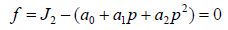
2.1 ‘Tsai-Wu’ yield surfaceGagnon and Gammon (1995) conducted triaxial compression experiments on icebergs at temperatures of −1, −6, −11, and −16 ℃, and at strain rates from 4×10⁻⁵ to 2.7×10⁻¹ s−1. Confining pressure, axial stress, and the ultimate strength were recorded. Derradji-Aouat (2000) translated axial stress and ultimate strength into the second invariant of deviatoric stress and found that these data can be fitted by a series of concentric parabolic curves. These curves can be expressed as Eq.(1), which has the same form as the Tsai-Wu yield surfaces. a0/a1/a2 are fitted parameters and change with temperature and strain rate.
|
(1) |
The focus of this study is the influence of the temperature gradient on sea ice behavior and the strain rate of iceberg ice is assumed to be constant. Experimental results (Michel and Toussaint, 1978), show that the transition rate from ductile to brittle leads to the greatest ice strength. A transition rate of approximately 4×10⁻³ s−1, is applied to the iceberg model in our simulations. Yield surfaces with constant strain rate and different temperatures are shown in Fig. 1. Parameters of these curves are shown in Table 1.

|
| Figure 1 Concentric elliptical ‘Tsai-Wu’ yield surfaces for different temperatures |
| Temperature/℃ | Strain rate/10−3 s−1 | a0/MPa2 | a1/MPa | a2 |
| −1 | 4.33 | 22.794 | 2.051 | −0.022 79 |
| −6 | 3.75-5.57 | 31.736 | 2.856 | −0.031 74 |
| −11 | 4.4 | 39.366 | 3.542 | −0.039 37 |
| −16 | 3.75-5.57 | 65.921 | 5.932 | −0.065 92 |
The temperature of icebergs varies throughout their depth. One of the most comprehensive reviews of field-testing results was conducted by Jones (2007) , as shown in Fig. 2.

|
| Figure 2 Experimental data of temperature gradients in icebergs (Jones, 2007 ) |
The temperature typically decreases rapidly from the surface to a depth of 8 m, then remains constant at depths below this. As observed experimentally, low temperatures make the ice firm and the rapid decrease in temperature means that the strength of ice increases rapidly with the increasing depth. Therefore, in ship-iceberg collisions, the contact force may increase rapidly as the penetration increases. In the range of engineering interest, from 0 to 2 m depth, temperature profiles can be represented by three kinds of regular curve: linear, moderate exponential, and sharp exponential, as shown in Fig. 3. The maximum assumed temperature profile is 1.3 m, chosen because the maximum of iceberg penetration in our simulation is about 1.2 m. Considering calculation convenience, these curves, instead of field data, are used to calculate the ice temperature at different depths.

|
| Figure 3 Three types of assumed temperature gradients in the iceberg model |
Implementation of the temperature gradient-dependent iceberg material model is illustrated in Fig. 4. In the simulation program, the distance between each ice element and the surface of the iceberg is calculated before collision occurs. Based on the distance, the precise temperature of each element is obtained from temperature profiles (shown in Fig. 3). Then, according to linear interpolation of the values in Table 1, accurate yield surfaces, to be applied in subsequent impact calculations, can be obtained for each element of the iceberg model. This means that temperature effects are reflected in the yield surfaces.

|
| Figure 4 Flow chart of the implementation of the temperature gradient dependent elastic-plastic iceberg material model in a finite element model |
The empirical failure criteria proposed by Liu et al.(2011) and improved by Gao et al.(2015) are adopted in this paper, as shown in Eq.(2). The failure criteria are based on the effective plastic strain and hydrostatic pressure:

|
(2) |
If the hydrostatic pressure, p, is smaller than the cut-off pressure pcut-off in a tensile stress state or the equivalent plastic strain, $\varepsilon _{eq}^p$, is larger than failure strain, ${\varepsilon _f}$, in a compressive stress state, the ice element is deleted to simulate pressure melting and damage. Erosion of elements violates the global mass equilibrium. Nevertheless, when an ice element is going to be deleted, its apparent stiffness decreases significantly which means it cannot bear any further load. Therefore, erosion of elements has a minor effect on the simulation of mechanical processes.
3 Numerical studyIn this section, collision between a spherical iceberg and a rigid plate are simulated. Calculated area-pressure curves are compared with the design code to validate the proposed iceberg material model. Then, FPSO-iceberg collision is simulated. The influence of the temperature gradient, temperature range, and the geometric shape of the iceberg on the impact process is studied by analyzing the relationship between the penetration-contact force and the energy dissipation ratio. All simulations are conducted in LS-DYNA using the Lagrange explicit integral method. The material model is realized by a user-defined subroutine in LS-DYNA.
3.1 Numerical validation of iceberg material modelThe area-pressure curve proposed by Masterson et al.(2007) is recommended in ISO 19906 for the ice loads in an Abnormal Level Ice Event (ALIE). Simulated area-pressure curves are compared with the design curves to validate the iceberg material model. As suggested by McKenna (2005) , a sphere can represent the mean iceberg model shape. Therefore, a spherical iceberg-rigid plate collision is simulated in this section. A 1 m radius sphere-shaped iceberg is fixed on the opposite side to the collision. The mesh size of the iceberg is determined based on the convergence analysis conducted by Gao et al.(2015) and is set to 50 mm×50 mm×50 mm. For the contact between a rigid plate and the iceberg, automatic_surface_to_surface in LS-DYNA is used and ‘soft option 2’ applied for a more accurate result. As the iceberg may come into contact with itself after erosion, eroding_singel_surface with ‘soft option 1’ is adopted to simulate the contact between new ice surfaces generated from erosion. The dynamic and static friction coefficients are both set to 0.15. The ice density is 900 kg/m3. Young’s modulus is 9 500 MPa. Poisson’s ratio is 0.3. The temperature range is assumed as −8 to −16 ℃ and the constant as −1 ℃. The temperature gradient is assumed to be linear. Comparison between the simulated area-pressure curve and the design codes are shown in Fig. 5.

|
| Figure 5 Comparison between simulated area-pressure curves and design codes |
The average of the simulated area-pressure curves corresponds well with the Molikpaq design curve (Timco and Sudom, 2013). Typical characteristics of area-pressure curves, i.e., pressure increasing rapidly as the contact area becomes smaller, are observed in the simulation results. The simulated curves are located within a reasonable range compared with different design curves.
3.2 Influence of temperature gradient on FPSO-iceberg collisionCollision between an FPSO side structure and an iceberg are simulated in this section. Details of the FPSO are shown in Table 2. The collision scenario is shown in Fig. 6. Both ends of the hold structure are fixed. A constant velocity of 2m/s in the x-direction, is applied to the iceberg using the displacement load method. In order to reduce previous stress induced by the applied load, a layer of rigid elements, which share common nodes with the iceberg, is added. Constant velocity is applied to this rigid layer. The height and side-lengths of the triangular prism are 3 m. The contact algorithm, typical mesh size of the iceberg, and friction coefficient are same as in the iceberg-rigid plate collision. The simulation time is 1 s. The collision point lies at the center between transverse web frames, as shown in Fig. 6. The temperature ranges are: constant −1 ℃, −1 to −16 ℃ and −8 to −16 ℃. The temperature gradients are linear, exponential moderate, and exponential sharp, as shown in Fig. 3.

|
| Figure 6 Collision scenario of FPSO and prismatic iceberg |
| Length overall/m | 288 |
| Molded breadth/m | 65 |
| Molded depth/m | 29.4 |
| Draft/m | 22 |
| Side shell spacing /m | 3.4 |
| Outer shell thickness/mm | 20 |
| Side stringer thickness/mm | 14 |
| Inner shell thickness/mm | 15 |
| Side height/m | 26 |
| Length between perpendiculars/m | 281 |
| Density/kg/m3 | 7890 |
| Young’s modulus/GPa | 2.1 |
| Poisson’s ratio | 0.3 |
| Yield stress/MPa | 285 |
| Failure strain | 0.2 |
| Typical element dimension/mm | 225 |
| Element type | Shell |
| Side length/m | 35 |
| Element number | 1.05×10⁵ |
| Material type | Piecewise_ linear_ plasticity |
The ratio of the ice dissipated energy to the total dissipated energy (equal to the sum of the energy dissipated by ice and that dissipated by the ship structure) can illustrate the relative strength between the iceberg and the side structure. When the ratio is large, the iceberg deforms severely and absorbs most of the striking energy. Therefore, the iceberg is weaker than the side structure. Alternatively, a low ratio means that the iceberg is stronger than the side structure. Fig. 7 shows the relationship between FPSO hull deformation and the ratio of iceberg dissipated energy to total dissipated energy. Hull deformation is defined as the largest displacement of the nodes in the contact surface of hull. Based on Fig. 7, the type of temperature gradient has little effect on iceberg strength. The ratio of linear gradients is larger than the exponential, meaning that the linear gradient case is the weakest among these three profiles. There is no significant difference between the moderate and the sharp exponential cases. From the prismatic curves in Fig. 8, it can be seen that temperature range has a more significant effect on iceberg strength than temperature gradient.

|
| Figure 7 Ratio of ice internal to all internal for three temperature gradients in a prismatic iceberg |

|
| Figure 8 Relation between penetration depth and ratio of ice internal to all internal for different temperature ranges (prismatic and cubic icebergs) |

|
| Figure 9 Dissipated energy for each component in side structure |
Energy dissipation by the components in the FPSO side structure reflects the resistance capability of each component and the most dangerous part of the collision process. Accordingly, strengthening methods for Arctic region structures can be analyzed. Fig. 9 shows the energy dissipation of side components over the range −8 to −16 ℃. At the beginning of the contact, the longitudinal girder and outer plating resist most of the contact load. As contact depth increases, especially after the outer plating is penetrated by a prismatic iceberg, energy dissipation by the outer plating increases rapidly. This is because the damage process of the outer plating dissipates a large amount of energy. After penetration appears (around 0.5 m in x-axial), the dissipated energy of the longitudinal girder and transverse web frame are similar, and the contribution of the platform resisting the contact force increase is obvious. It should be noted that, for other contact positions, e.g., the intersection of the longitudinal girder and transverse web frame, the energy dissipation of these components may differ.
| Percentage of dissipated energy | Transverse web frame | Outer plating | Longitudinal girder | Platform |
| At 0.5 m penetration | 24.94 | 45.94 | 25.4 | 3.72 |
| At 1 m penetration | 16.44 | 56.61 | 16.16 | 10.79 |
Both experimental (Frederking and Timco, 2000) and numerical studies (Storheim et al., 2012) show that the geometric shape of ice affects the ice load. In this section, collisions between the FPSO side structure and icebergs with four geometrical shapes are simulated. Cubic, prismatic, conic, and spherical iceberg models are shown in Fig. 10. The collision scenario is the same as that in section 3.2. A linear temperature gradient is adopted and the temperature ranges are constant −1 ℃, −1 to −16 ℃ and −8 to −16 ℃.

|
| Figure 10 Numerical model of different types of icebergs at the end of the collision process |
The simulation results for the prismatic shape, show that only icebergs at temperatures ranging from −8 ℃ to −16 ℃ penetrate the outer plating. All prismatic icebergs suffered damaged ice elements. For the spherical shape, icebergs at all temperatures penetrated the outer plating and almost no element was deleted during the collision process, as shown in Fig. 10. The cubic icebergs suffered from a lot of deleted elements, which led to large plastic deformation of the side structure. The conic icebergs did not suffer from deleted elements, which means there was no penetration of the outer plating.
It is indicated from Figs. 8 and 11 that temperature range has little influence on the relative strength between cubic and spherical icebergs and structures, but has a strong effect on prismatic and conic icebergs. This is because the structure of cubic and spherical shape is strong and almost no elements are deleted in the collision process. Therefore, the temperature range inside is not reflected. In contrast, lots of ice elements are deleted in prismatic and conic iceberg. Consequently, temperature range is reflected and has some effect on iceberg strength.

|
| Figure 11 Relation between penetration depth and ratio of ice internal to all internal for different temperature ranges (conic and spherical icebergs) |
In summary, the damage from ship-iceberg collisions not only depends on the relative strength of the iceberg and the ship’s hull, but also on the local contact shape of the iceberg. The energy ratios of prismatic and conic icebergs are located in a similar range which indicates that they have similar strength relative to the ship’s structure. Prismatic icebergs penetrate the outer shell, while cubic icebergs do not. The difference is because the contact area of a conic iceberg is considerably larger than that of prismatic one. Therefore, distribution of the contact force within the contact area is homogenous and no stress concentration is observed. In the prismatic case, excess stress distributes within the relatively small contact area. Fig. 12 shows the von Mises stress diagrams for the conic and prismatic cases. A similar condition is observed when comparing spherical and cubic icebergs. Both have similar energy ratios, and while the spherical iceberg penetrates the outer shell, the cubic one does not.

|
| Figure 12 Von Mises stress diagrams of side structure |
An elastic-plastic iceberg material model considering temperature gradient effects proposed by the authors is adopted in the simulation of FPSO-iceberg collision. The model behaves as an elastic-perfect-plastic material. ‘Tsai-Wu’ yield surfaces are applied. Temperature effects are reflected by the size of the yield surfaces. Based on the numerical simulation results, the main conclusions are drawn as follows:
1) Temperature distribution and range can influence the relative strength between the iceberg and the FPSO side structure. With a low temperature range or sharp temperature distribution, the iceberg may penetrate the outer plating of the side structure, while at a high temperature range or moderate profile, there may be no penetration.
2) Damage to the side structure depends on iceberg shape and the relative strength between the iceberg and the structure. A blunt shape with high strength, e.g. a cubic iceberg, may not penetrate the outer plating. A sharp geometric shape with relatively weak strength, e.g. a prismatic iceberg, may penetrate the outer plating.
3) During the collision process, the influence of temperature on the relative strength of weakly-structured icebergs is more significant than that in strongly-structured icebergs. This is because a lot of ice elements are deleted from icebergs with a weak structure and the temperature range and distribution are reflected in this. In contrast, few elements are deleted in strong icebergs, and the temperature range and profile are not reflected.
AcknowledgementThe work contained in this paper is part of a joint-research project between the State Key Laboratory of Ocean Engineering at Shanghai Jiao Tong University and the Department of Shipping and Marine Technology at Chalmers University of Technology. The authors would like to thank Dr. Jonas Ringsberg at Chalmers University of Technology for his discussions and suggestions for this paper.
| Bergan PG, Cammaert G, Skeie G, Tharigopula V, 2010. On the potential of computational methods and numerical simulation in ice mechanics. 9th World Congress on Computational Mechanics and 4th Asian Pacific Congress on Computational Mechanics, Sydney, 012102. DOI:10.1088/1757-899X/10/1/012102 |
| Derradji-Aouat A, 2000. A unified failure envelope for isotropic fresh water ice and iceberg ice. Proc. of the ETCE/OMAE-2000 Joint Conference, Energy for the New Millennium, New Orleans. |
| Ding Dewen, 1999. Introduction to engineering sea ice. Beijing: China Ocean Press30-31. |
| Frederking R, Timco G, 2000. Sea ice floe impacts-large scale basin experiments. Proceedings of the Tenth International Offshore and Polar Engineering Conference ISOPE'00, Seattle, 640–645. |
| Gagnon RE, Gammon PH, 1995. Triaxial experiments on iceberg and glacier ice. Journal of Glaciology, 41(139), 528–540. DOI:10.3198/1995JoG41-139-528-540 |
| Gao Y, Hu Z, Ringsberg JW, Wang J, 2015. An elastic-plastic ice material model for ship-iceberg collision simulations. Ocean Engineering, 102, 27–29. DOI:10.1016/j.oceaneng.2015.04.047 |
| Hill B, 2005. Ship collisions with iceberg database. 7th International Conference and Exhibition on Performance of Ships and Structures in Ice, Banff, 172–178. |
| Jones SJ, 2007. A review of the strength of iceberg and other freshwater ice and the effect of temperature. Cold Regions Science & Technology, 47(3), 256–262. DOI:10.1016/j.coldregions.2006.10.002 |
| Liu Z, Amdahl J, Løset S, 2011. Plasticity based material modelling of ice and its application to ship–iceberg impacts. Cold Regions Science and Technology, 65(3), 326–334. DOI:10.1016/j.coldregions.2010.10.005 |
| Masterson DM, Frederking RMW, Wright B, Kerna T, Maddock WP, 2007. A revised ice pressure-area curve. 19th International Conference on Port and Ocean Engineering under Arctic Conditions, Dalian, 305–314. |
| McKenna R, 2005. Iceberg shape characterization. 18th International Conference on Port and Ocean Engineering under Arctic Conditions, POAC 2005, Potsdam, 555–564. |
| Michel B, Toussaint N, 1978. Mechanisms and theory of indentation of ice plates. Journal of Glaciology, 19, 285–300. DOI:10.3198/1977JoG19-81-285-300 |
| Schulson EM, Duval P, 2009. Creep and fracture of ice. Cambridge University Press, Cambridge, 240–241. |
| Storheim M, Kim E, Amdahl J, Ehlers S, 2012. Iceberg shape sensitivity in ship impact assessment in view of existing material models. ASME 31st International Conference on Ocean, Offshore and Arctic Engineering, Rio de Janeiro, 507–517. |
| Timco GW, Sudom D, 2013. Revisiting the Sanderson pressure-area curve: Defining parameters that influence ice pressure. Cold regions science and technology, 95, 53–66. DOI:10.1016/j.coldregions.2013.08.005 |