2. Department of Metallurgical and Materials Engineering, Ahmadu Bello University, Zaria P.M.B 1045, Nigeria;
3. Department of Chemical, Metallurgical and Materials Engineering, Tshwane University of Technology, Pretoria X680, South Africa;
4. Department of Mechanical Engineering, Ahmadu Bello University, Zaria P.M.B 1045, Nigeria
Cathodic protection is commonly used to protect engineering structures, such as pipelines, underground storage tanks, locks, and ship hulls from corrosion. It is a method of preventing corrosion by minimizing the difference in potential between anode and cathode. This is achieved by supplying current to the structure to be protected from some outside source. Once, enough current has been applied, the whole structure will be at one potential; thus, anode and cathode sites will not exist, as stated by UFC(2005). According to Baxter and Britton(2006), cathodic protection prevents corrosion by converting all the anodic(active)sites on the metal surface to cathodic(passive)sites by supplying electrical current(or free electrons)from an alternate source.
There are two main methods of applying cathodic protection to metals as suggested by Talbot and Talbot(1997)namely: the impress current system and the sacrificial anode. In the impress current system, a rectifier converts an external AC power source to the required DC power source. In this type of cathodic protection system inert anodes are installed around the structure to be protected and DC power is supplied to the anodes through wires. In the sacrificial anode system, the anode is directly connected to the structure either by welding or mechanical coupling, and the anode corrodes instead of the metal; hence, the anode is said to be sacrificed. Cathodic protection using sacrificial anodes has gained general acceptance as a means of preventing and protecting materials from corrosion. This is because it has the advantage of being simple to install, independent of an external power source, suitable for localized protection, and less liable to interact with neighboring structures as described by Baxter and Britton(2006).
Aluminum alloys are normally used for protecting steel structures in seawater because of their better current conductivity(low resistivity), higher operating potential, and because they supply largest number of electrons for protection per unit mass. The problem with pure aluminum is that it passivates easily by forming an oxide film that prevents contact between the metal and the environment(Corrosion-Doctor, 2009). Aluminum alloys are the preferred metals for use as sacrificial anodes in seawater compared with Mg and Zn. This is because aluminum alloys have a large electrochemical equivalent, low density, are not wastefully consumed, and give better current output according to Genesca and Juareg(2007). Pure aluminum is not used as anode material because it easily forms a passive layer of γ-Al2O3 on its surface as reported by Gurrappa(1984). For used as galvanic anodes, aluminum alloys containing activating alloying elements that hinder or prevent the formation of surface films, are employed. The continuity of the film is affected by the microstructure of the metal, as well as the presence and volume fraction of second-phase particles. The alloying elements that hinder or prevent the formation of surface film on aluminum are Zn, Mg, Ga, In, Sn, Bi and Ti(Baeckmann et al., 1997). In our previous work, an attempt was made to alloy only Zn with aluminum for sacrificial seawater anodes which resulted in a good performance(Muazu and Yaro, 2011). This necessitated the present research, which looks at the possibility of alloying aluminum with Mg and Zn in order to enhance its performance as a sacrificial anode for the protection of mild steel in seawater. These elements were chosen as they form eutectic compounds that help in the non-passivation of the aluminum anode as reported in MHB(1990).
2 Experimental procedure 2.1 Materials and equipmentThe high purity aluminum used in this research was obtained from Northern Cable Company(NOCACO)Kaduna and the Mg, Zn, and natural seawater from Lagos(Nigeria). Distilled water, acetone, ethanol, and etchants were also used. The composition of the produced Al-Zn-Mg alloy is shown in Table 1.
| S/N | wt% Al | wt% Zn | wt% Mg |
| 1 | 97.0 | 2.0 | 1.0 |
| 2 | 94.0 | 4.0 | 2.0 |
| 3 | 91.0 | 6.0 | 3.0 |
| 4 | 88.0 | 8.0 | 4.0 |
The equipment comprised a molding box, permanent molding pipes, a digital weighing machine, a platinum reference electrode, an electrical resistance furnace, a pyrometer, and a metallurgical microscope with a built-in-camera.
2.2 Methods 2.2.1 Sample productionProduction of the Al-Zn-Mg alloys was carried out using permanent mold casting. The aluminum obtained was re-melted in a muffle furnace and, proportionate amounts of Zn and Mg were added to produce alloys of composition 2%-8% Zn and 1%-4% Mg. Preheated permanent molds with a 19 mm diameter and 400 mm length were used to produce the cast bars. After casting, the samples were cut to(19 mm×10 mm)for the cathodic protection test; the samples were then polished, degreased in acetone, dried, and weighed. The samples initial weights were taken using the weighing machine model: Mettler AC 100 Ag Ch-8606 with 0.000 1 g accuracy, then stored in a desiccator. Commercial 100% pure aluminum was cast as the control.
Mild steel pipes, 60 mm in length with internal and external diameters of 19 and 27 mm, respectively, were weighed and mechanically coupled with the aluminum alloy. Before coupling, the open circuit potential of the anodes and the steel in the seawater was measured with respect to the Standard Hydrogen Electrode(SHE).
Thereafter, the samples were coupled with the mild steel, and immersed in natural seawater. The weight loss, polarized potential, and current required were then determined every week for a period of 8 weeks.
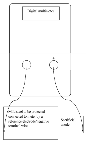
2.2.2 Potential determinationAfter the test samples were immersed in the natural seawater, a platinum reference electrode was also immersed. The electrode and the samples were connected to a digital multimeter, which was used to measure the polarization potential(closed circuit potential)with respect to Standard Platinum Reference Electrode(SPRE). The arrangement for the measurement of the potential is given in Fig. 1. The corrosion products formed on the surface were removed by scrubbing under running tap water using a fine rubber bung and after swabbing the surfaces with cotton wool soaked in ethanol; the specimens were dried and re-weighed.
|
| Fig. 1 Schematic developed for the measurement of potential and current |
The chemical composition of the seawater used was determined using a double-beam digital Atomic Absorption Spectrophotometer(AAS), model number AA-650. The pH was determined using a pH meter(model pHS-25).
2.2.4 Current determinationThe protection current provided to the steel by the anodes after coupling and the polarized potential of the couples were measured using a digital multimeter; the connection for the measurement of the current is given in Fig. 1.
2.2.5 Determination of current carrying capacity and anode efficiencyThe theoretical current carrying capacity value CCTH corresponding to each alloy composition was calculated using Eq.(1)from Baeckmann et al.(1997)as shown in Table 1.
| ${\rm{C}}{{\rm{C}}_{{\rm{TH}}}} = \frac{{\sum {{X_i}{Q_i}} }}{{100}}$ | (1) |
where Xi is the mass fraction in percent of the alloying element, with current content Qi(theoretical current capacity)tabulated in Table 1.
The anode efficiency(E%)was determined using the relationship in Eq.(2)according to Gabriele and Canterbury(2003).
| $E(\%)= \frac{{{\rm{C}}{{\rm{C}}_{\rm{A}}}}}{{{\rm{C}}{{\rm{C}}_{{\rm{TH}}}}}} \times 100$ | (2) |
where CCA and CCTH are the actual and theoretical current carrying capacity, respectively.
The actual current carrying capacity was calculated using Eq.(3).
| ${\rm{C}}{{\rm{C}}_{\rm{A}}} = \frac{{It}}{{\left({{W_i} - {W_f}} \right)}} \times 100$ | (3) |
where I is the current in amperes, t is the time in hours, and Wi and Wf are the initial and final weights in grams, respectively.
2.2.6 Protection efficiency determinationThe Protection Efficiency(PE)given to the steel(cathode)by the sacrificial anode was determined for the 7th and 8th week by using Eq.(4).
| ${\rm{PE}} = \frac{{{W_2}}}{{{W_1}}}$ | (4) |
where W1 is the initial weight of the steel and W2 is the final weight of the steel.
2.2.7 Anode mass requirementThe anode mass requirement was calculated using Eq.(5)according to Meillier(2000).
| $M = \frac{{8760{I_m}t}}{{\mu \varepsilon }}$ | (5) |
where Im is the maintenance current, t is the design life in years, μ is the utilization factor, normally 0.8 for Al-based sacrificial anode from Earnest(2004), and ε is the electrochemical capacity of the anode material in A∙h/kg(CCTH).
2.2.8 Metallographic analysisThe samples for metallographic examination before and after corrosion were ground on 60-600 grit-size grades of SiC emery paper using water as a coolant. Rough and fine polishing was carried out on the samples before corrosion using a 1.0 micron aluminum polishing powder and a 0.5 micron alumina powder on a rotating disc of nap cloth. Fine polishing was carried out on the samples after corrosion. The samples were etched using 5 mL hydrogen peroxide and 2 mL nitric acid in 10 mL of distilled water, the microstructure was recorded using an optical microscope with a built-in-camera, Model number NJF-120A.
3 Results and discussionTable 2 gives the calculated theoretical current capacity for the cast sacrificial anodes. It can be seen that the current carrying capacity of the alloys decreased with an increase in composition of the alloying elements(Zn and Mg)in all the cast alloys. Table 3 gives the chemical composition and pH of the seawater while Table 4 gives the chemical composition of the mild steel.
| Composition | Polarization potential of the couple/V | Maintenance current/mA | Anode efficiency/% | Theoretical current capacity(CCTH/ε)/(A·h·kg-1) |
| Pure aluminum | -0.62 | 0.03 | 21.23 | 2 981 |
| Al-2%Zn-1%Mg | -0.77 | 0.14 | 70.75 | 2 930 |
| Al-2%Zn-2%Mg | -0.78 | 0.14 | 61.56 | 2 922 |
| Al-2%Zn-3%Mg | -0.77 | 0.14 | 76.03 | 2 915 |
| Al-2%Zn-4%Mg | -0.79 | 0.14 | 79.12 | 2 907 |
| Al-4%Zn-1%Mg | -0.82 | 0.16 | 77.19 | 2 887 |
| Al-4%Zn-2%Mg | -0.85 | 0.15 | 75.80 | 2 879 |
| Al-4%Zn-3%Mg | -0.84 | 0.16 | 76.04 | 2 871 |
| Al-4%Zn-4%Mg | -0.87 | 0.16 | 80.60 | 2 864 |
| Al-6%Zn-1%Mg | -0.91 | 0.17 | 88.36 | 2 844 |
| Al-6%Zn-2%Mg | -0.86 | 0.17 | 86.97 | 2 836 |
| Al-6%Zn-3%Mg | -0.85 | 0.19 | 78.63 | 2 828 |
| Al-6%Zn-4%Mg | -0.79 | 0.17 | 50.86 | 2 820 |
| Al-8%Zn-1%Mg | -0.78 | 0.19 | 78.83 | 2 800 |
| Al-8%Zn-2%Mg | -0.80 | 0.18 | 73.78 | 2 793 |
| Al-8%Zn-3%Mg | -0.85 | 0.17 | 68.22 | 2 785 |
| Al-8%Zn-4%Mg | -0.77 | 0.18 | 71.72 | 2 777 |
| Description | K | Na | Ca | Mg | Cu | Zn | Mn | Fe | Cr | Co | Ni | P |
| Concentration/10−6 | 3.90 | 5.66 | 2.00 | 0.35 | 0 | 0.225 | 0.25 | 0.75 | 0.00 | 0.55 | 1.15 | 0.50 |
| Element | C | Si | Mn | P | S | Cr | Mo | Ni | Sn | Cu | V |
| Percent | 0.13 | 0.15 | 0.47 | 0.043 | 0.006 | 0.01 | 0.01 | 0.01 | 0.001 | 0.03 | 0.002 |
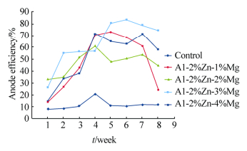
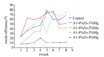
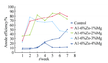
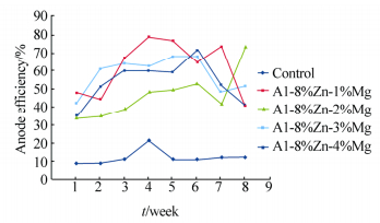
Table 3 shows the heavy metal content of the seawater, Na showed the highest concentration(10−6); the determined pH of the seawater is 8.33. Figs. 2-5 show the variation of anodic efficiency with time for Al-Zn-Mg, sacrificial anodes in seawater. In Figs. 2-5, it can be observed that there is an increase in anodic efficiency with time for most Al-Zn-Mg alloys. The highest anodic efficiency value(88.36%)was obtained at 6% Zn and 1% Mg. The low efficiency value and the drop in efficiency for some of the sacrificial anodes can be attributed to re-passivation and the chunk effect, which is the physical detachment of the metal from the bulk sacrificial anode. The missing metal is no longer useful for cathodic protection and results in lower efficiency as stated by Gabriele and Canterbury(2003).
|
| Fig. 2 Variation of anode efficiency with time for Al-2%Zn-xMg sacrificial anodes |
|
| Fig. 3 Variation of anode efficiency with time for Al-4%Zn-xMg sacrificial anodes |
|
| Fig. 4 Variation of anode efficiency with time for Al-6%Zn-xMg sacrificial anodes |
|
| Fig. 5 Variation of anode efficiency with time for Al-8%Zn-xMg sacrificial anodes |
The open circuit potential of the sacrificial anode produced lies in the range −1.23 to −1.47V SHE and that of the steel was −0.47 V SHE. Polarization potential values were obtained for pure aluminum-steel and Al-Zn-Mg/steel couples(Table 2). The values obtained for the pure aluminum-steel couple(−0.62 V)are within the recommended values(below −0.5 V SHE in the iron/steel Pourbaix diagram)of the standard hydrogen electrode(Corrosion-Doctor, 2009). The polarization potential obtained for the Al-Zn-Mg/steel couples were within the recommended range(below −0.5 V SHE in the iron/steel Pourbaix diagram), with the Al-6%Zn-1%Mg-steel couple having the most negative potential at −0.91 V SHE. The protection efficiency given to the steel by the aluminum sacrificial anode was calculated. Pure aluminum had the least protection efficiency of 93.13% and 92.84% at the 7th and 8th week, respectively. For the Al-Mg sacrificial anodes(Table 5), Al-6%Zn-1%Mg showed a protection efficiency of 99.66% and 99.47% at the 7th and 8th week, respectively.
| Composition | Calculated degree of protection | |
| 7th week | 8th week | |
| Pure aluminum | 93.13 | 92.84 |
| Al-2%Zn-1%Mg | 96.68 | 97.56 |
| Al-2%Zn-2%Mg | 97.59 | 96.37 |
| Al-2%Zn-3%Mg | 97.94 | 97.49 |
| Al-2%Zn-4%Mg | 98.52 | 98.15 |
| Al-4%Zn-1%Mg | 97.73 | 97.52 |
| Al-4%Zn-2%Mg | 97.12 | 96.69 |
| Al-4%Zn-3%Mg | 96.52 | 96.54 |
| Al-4%Zn-4%Mg | 95.49 | 95.65 |
| Al-6%Zn-1%Mg | 99.66 | 99.47 |
| Al-6%Zn-2%Mg | 99.33 | 99.06 |
| Al-6%Zn-3%Mg | 96.83 | 96.87 |
| Al-6%Zn-4%Mg | 96.37 | 96.06 |
| Al-8%Zn-1%Mg | 99.14 | 98.98 |
| Al-8%Zn-2%Mg | 95.89 | 95.19 |
| Al-8%Zn-3%Mg | 97.49 | 97.34 |
| Al-8%Zn-4%Mg | 96.84 | 96.69 |
The protection efficiency results obtained show that pure aluminum has the least protection efficiency. Thus, the pure aluminum anode could not give the steel enough protection, and as a result, the steel corrode. For the Al-Zn-Mg sacrificial anodes, Al-6%Zn-1%Mg showed the highest degree of protection(protection efficiency). This implies that the anode gave the steel enough protection.
The micrographs of the alloys before and after the corrosion test are given in Figs. 6-10. The micrographs show the second-phase particles in the matrix of Al before use as a sacrificial anode, and the diminishing of the sacrificial anode when employed to cathodically protect the mild steel pipes over a period of 8 weeks.

|
| Fig. 6 Optical micrograph of as-cast aluminum showing α-solid-solution(white-matrix)(left), and aluminum/steel couple after immersion in seawater for 8 weeks ×200(right) |
|
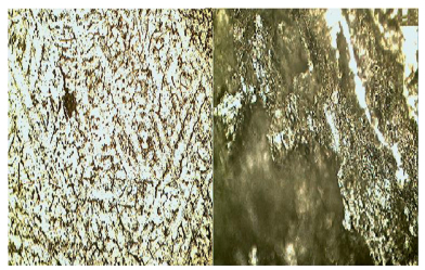
| Fig. 7 Optical micrograph of as-cast Al-2%Zn-4%Mg before coupling and immersion in seawater(left), and Al-2%Zn-4%Mg/steel couple after immersion in seawater for 8 weeks showing dark regions of corrosion product ×200(right) |
|
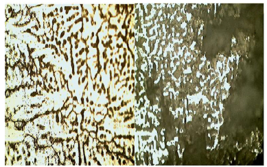
| Fig. 8 Optical micrograph of as-cast Al-4%Zn-4%Mg showing intermetallic second phase particles of Mg5Al3(dark)and Mg5Al8(gray)(left), and Al-4%Zn-4%Mg/steel couple after immersion in seawater for 8 weeks ×200(right) |
|
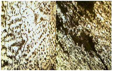
| Fig. 9 Optical micrograph of as-cast Al-6%Zn-1%Mg showing intermetallic second phase particles of Mg5Al3(dark)and Mg5Al8(gray)(left), and Al-6%Zn-1%Mg/steel couple after immersion in seawater for 8 weeks ×200(right) |
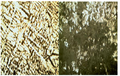
|
| Fig. 10 Optical micrograph of as-cast Al-8%Zn-1%Mg showing intermetallic second phase particles of Mg5Al3(dark)and Mg5Al8(gray)(left), and Al-8%Zn-1%Mg/steel couple after immersion in seawater for 8 weeks ×200(right) |
The low initial efficiency of the Al-Zn-Mg sacrificial anode could be attributed to the formation of a stable oxide layer of alumina, which retards the dissolution rate of metal in a saline medium. But as the exposure time increased, the stable oxide layer broke down and could no longer protect the metal from further dissolution. This is in line with the observation by Shibli et al.(2008).
The results indicate that the second-phase particles are probably responsible for depassivating the aluminum. The second-phase particles in the Al-Zn-Mg alloys are: hexagonal Mg3Zn2 and body-centered cubic Al2Mg3Zn3 phases, probably formed as shown in Figs. 7-10 according to MHB(1990). These second-phase particles led to breakdown of the passive film of Al2O3 formed on the aluminum surface, and resulted in the increase in efficiency of the aluminum sacrificial anode, similar to the report by Gabriele and Canterbury(2003).
4 ConclusionsFrom this study, it can be concluded that anode efficiency of the Al-Zn-Mg sacrificial anode is dependent both on time and composition. The polarization potential obtained for the couples lie within the immunity region of steel: less than or equal to −0.5 V SHE. The protection efficiency data obtained show that pure aluminum cannot give steel enough protection. The presence of second-phase particles of Al2Mg3Zn3 and Mg3Zn2 probably aid in the dissolution of the Al-Zn-Mg sacrificial anode. The pH of the seawater is within the range wherein aluminum passivates(7.4-8.4). Most importantly, the anode mass requirement can be calculated using ε(CCTH)at any given time(t in years). Of the sacrificial anode produced the Al-6%Zn-1%Mg gave the steel the highest protection, thus, additions of 6% Zn and 1% Mg to aluminum are recommended for sacrificial anodes for underground steel protection.
| Baeckmann VW, Shwenk W, Prinz W (1997). Cathodic protection handbook: Theory and practice of electrochemical protection processes. Gulf Publishing Company, Houston, 56, 124. |
| Baxter D, Britton J, 2006. Offshore Cathodic Protection 101. 10851 Train Court, Houston, USA, 12, 48. |
| Corrosion–Doctors.org/Corrosion-Thermodynamics/Pot ential-pH- diagram-water, htm, 2009. |
| Earnest WK, 2004. Corrosion protection for offshore pipelines. Corrosion Conntro Technologies, Dublin, 63. |
| Gabriele DF, Canterbury JD, 2003. Corrosion behaviour of Magnesium sacrificial anodes in tap water. Corrosion and Protection Centre, Manchester, 51. |
| Genesca J, Juareg J, 2007. Development and testing of galvanic anodes for cathodic protection. Contributions to Science Journal, 1(3), 331-334. |
| Gurappa J, 1984. Corrosion prevention and control. Science Press, New Delhi, India, 44, 69. |
| Meillier A, 2000. A review of galvanic anode cathodic protection design procedure. Corrosion Control Services Limited, Telford, UK, 43-62. |
| Metals Hand Books (MHB), 1990. Properties and selection; Nonferrous alloys and special–purpose material. American Society of Metals (ASM), Vol. 2, 143, 167. |
| Muazu A, Yaro SA, 2011. Effects of zinc addition on the performance of Aluminium as sacrificial anode in seawater. Journal of Minerals and Materials Characterization and Engineering, 10(2), 185-198. DOI: 10.4236/jmmce.2011.102013 |
| Shibli SMA, Archana SR, Muhammed PA, 2008. Development of nano Cerium oxide incorporated aluminium alloy sacrificial anode for marine applications. Corrosion Science, 50(8), 2232-2238. DOI: 10.1016/j.corsci.2008.06.017 |
| Talbot DEJ, Talbot JDR, 1997. Corrosion science and technology. CRC Press, London, 27-103. |
| Unified Facilities Criteria (UFC), 2005. Cathodic protection. Department of Defence, USA, 34-42. |


