1 Introduction
Various multi-hull ship designs exist and are used for very specific applications because of their unique hydrodynamic behaviors. For example, catamarans move at high speeds because ofa stern shape that allows the installation of waterjet propulsors, and thus, they are suitable for use during high speed requirements. On the other hand, small waterplane area twin hulls (SWATHs) are more suitable whenhigh seakeeping performances are required.
With the availability of a large variety of possible hull types, there also arises the possibility for the creation of new crossover designs that incorporate the best features of these different hulls to overcome their limitations. The proposed semi-SWATH design settles exactly in the context of designs created to combine the valuable performances of other more classic parent hullswhile attempting to reduce or even avoid their known drawbacks.
There are very few studies that adopt the semi-SWATH design and that focus on small and medium-size passenger ferries.
The first study on this type of hull was proposed by Shack (1995) , who described the SeaJet project. Holloway (1998) studied the seakeeping behaviors of both SWATH and semi-SWATH vessels using a time-domain strip-theory approach for high Froude numbercases. Armstrong and Clarke (2009) performed resistance modeling tests for both V- and U-shaped semi-SWATH hulls; they studied the seakeeping performance using a strip-theory-based approach. In the same year, Zaraphonitis et al. (2009) detailed an experimental-numerical study comparing two semi-SWATH designs.
Majority of published work related to the semi-SWATH design actually focuses on the hydrodynamic performance of parent hulls, i.e., the well-known catamarans and SWATHs. These studies deal with both experimental and numerical predictions of performance.
Regarding fast catamaran hulls, experimental tests for resistance and seakeeping, including added resistance computations, have been conducted by Molland et al. (2000) . Brizzolara et al. (1998) presented numerical computations comparing inviscid solutions obtained by a boundary element method (BEM) with the results of experimental towing tank tests. Notable among others was the work performed by Kring and Sclavounos (1995) , who approached the problem of three dimensional evaluation of ship motions via time-domain inviscid simulations.
Regarding SWATHs, Papanikolaou et al. (1991) showed the design of a passenger ferry based on this type of hull, with particular emphasis on its hydrodynamic aspects. They used optimization techniques to test a considerable number of design variations.
The optimization-based approach has also been used by Brizzolara (2004) and more recently reconsidered by Brizzolara and Vernengo (2011a; 2011b);in the former study, the geometry of the hull was described by a polynomial function, and this was substituted in the latter study by a more flexible BSpline-based model. Brizzolara and Gaggero (2006) developed an integrated design approach for SWATH passenger ships; this approach includes wave resistance performances and wasevaluated using the Mitchell method.
Recently, Vernengo et al. (2015) proposed an application of hydrodynamic-shape-optimization-based design to a semi-SWATH passenger ferry; the hull shape was described by a fully parametric model that considered both local and global variations. In addition, multi-objective optimization with respect to calm water resistance and seakeeping was performed by a modern genetic algorithm.
In this study, calm water resistance and seakeeping responsesof the proposed semi-SWATH design in regular head waves are computed and systematically compared with those of a classical single-strut SWATH design. The tested Froude number for both resistance and seakeeping ranges from 0.4 to 0.8, i.e., from medium to high speeds, for displacement hulls.
A BEM developed by Bruzzone (1994; 2003) is used to perform hydrodynamic computations of both resistance and seakeeping responses.
The BEM is based on Rankine source distributions over the hull and free surface; structured quadrilateral panel meshes are used to discretize both the hull and free surface. A set of boundary value problems for the evaluation of wave resistance, radiation, and diffraction problems is formulated. The abovementioned threeproblemsare linearized with respect to the double-model flow; the combined dynamic and kinematic boundary conditions, together with the relevant body boundary condition, are applied. Pressure integration over the hull surface is used to computewave resistance, radiation, and diffraction forces. Vertical motions are solved in the frequency domain.
A preliminary validation of the results of the numerical method used here has been performed using readily available experimental data for conventional SWATH vessels.
2 Validation of the seakeeping method for conventional SWATHSWATH-6A reportedby Kallio (1976) has been selected for the preliminary validation of the seakeeping method for this type of hull. This is a conventional SWATH for which at the David Taylor Naval Ship Research Centre, experimental seakeeping model tests have previously been performedfor various speeds in both regular and irregular waves. This SWATH has been tested with three strut configurations (A, B, and C), including single (A and B) and double (C) struts. Among them, the conventional single-strut configuration (A) has been selected for the present analysis. The vessel selected in this study, SWATH-6A, is equipped with a pair of passive stabilizer finsplaced between two demi-hulls at the bow and stern.
The main dimensions of SWATH-6A and those of stabilizer fins are listed in Tables 1 and 2, respectively.
| Characteristic / Units | Value |
| Δ/ t | 2 900 |
| LOA / m | 73.15 |
| LWL / m | 52.5 |
| XG aft of FPP / m | 24.54 |
| KG / m | 10.36 |
| ρyy | 0.233 |
| T / m | 8.13 |
| s/LWL | 0.44 |
| Aft fin | Forw fin | |
| Chord | 4.48 | 2.59 |
| Span | 5.36 | 3.11 |
| Max thickness | 0.67 | 0.39 |
| Profile type | NACA64015 | NACA64015 |
To perform the validation of the seakeeping method for the SWATH-6Athe effect of passive stabilizer fins fitted on the model needs to be considered in the seakeeping response computation. The technique proposed by Sclavounos and Borgen (2004) has then been implemented in the BEM. Using this method, the fins are not discretized as new bodies in BEM computation, but rather, their effect due to generated lift forces are considered in the hydrodynamic coefficient derivation. The main changes to the hydrodynamic coefficients proposed by this method and those used in the present analysis are briefly recalled in the following paragraphs (only the part of the theory relating to vertical motions is considered).
The lift force of the fins, F, is directly computed using Prandtl’s lifting line theory and is expressed as follows:
$$F = {{AR} \over {AR + 2}}\left ( {\rho {\rm{\pi }}S{U^2}} \right) $$
(1)
where AR is the aspect ratio correction for three-dimensional effects, S is the fin-wetted surface, and U is the advancing speed of a ship.
The method then derives a corrected formula for restoring and damping coefficients;the corrected formula includes the effect of the lift force of the fins. The related restoring and damping coefficients for heave and pitch motions modified by the effect of the lift fins are written as
$${C_{35\_Tot}} = {C_{35}} + F$$
(2)
$${C_{55\_Tot}} = {C_{55}} + {x_{Foil}} \cdot F$$
(3)
$${B_{35\_Tot}} = {B_{35}} + {x_{Foil}} \cdot {\raise0.5ex\hbox{$\scriptstyle F$}
\kern-0.1em/\kern-0.15em
\lower0.25ex\hbox{$\scriptstyle U$}}$$
(4)
$${B_{35\_Tot}} = {B_{55}} + x_{Foil}^2 \cdot {\raise0.5ex\hbox{$\scriptstyle F$}
\kern-0.1em/\kern-0.15em
\lower0.25ex\hbox{$\scriptstyle U$}}$$
(5)
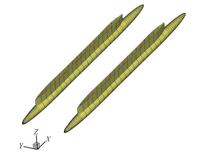
The perspective view of the hull panel mesh used for the BEM computations is shown in Fig. 1. As mentioned previously, stabilizer fins are not included in the discretized geometry. As shown inFig. 1, the underwater part of the SWATH hull is cylindrical with slight differences in the bow and stern closures. The single-strut waterline is straight for most of the length and closes at both ends with a wedge-like shape. A strut having a cylindricalshape is obtained by a simple vertical extrusion of this waterline shape.
|
| Fig. 1 SWATH-6A body mesh used in the BEM computations |
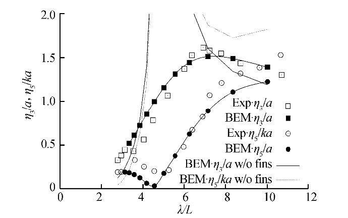
SWATH-6A heave and pitch responses have been computed for a tested experimental condition. The model was towed at a forward speed corresponding to Fn=0.45 (relative to the length of the waterline, LWL). The numerical response amplitude operators (RAOs) of heave and pitch motions are compared with those measured in the experiments by Kallio (1976) and shown in Fig. 2. Here, the heave and pitch, which wereexperimentally measured, are represented by empty squares and circles, respectively, while the solid curves with filled squares and circles represent the corresponding computational responses. The heave and pitch responses of the hull without fins are shown by solid and dashed lines, respectively.
|
| Fig. 2 Comparison of the numerical (line) vs experimental (dots) SWATH-6A heave (squares) and pitch (circles) RAOs |
The peaks of the RAOs when the fins are not considered are clearly over predicted with respect to the experiments, due to the absence of any fin damping correction. Considering stabilizer fins effects resultsin strongly modified responses; the peak of the heave is damped out, but the trend is roughly maintained while the pitch RAO is changed in both absolute value and trend.
Finally, the behaviors of both heave and pitch responsesconsidering the stabilizer fins and hence the trends and peak location and amplitude are generally well predicted. A slight shift of the pitch curve to lower values is found. The agreement between the numerical and experimental results is considered satisfactory over the entire range of non-dimensional wavelengths; it can be concluded that using the foregoing seakeeping method also on the proposed kind of hull shapes ensures a acceptable level of confidence.
3 Comparative analysis of resistance and seakeeping performanceTo compare the resistance and seakeeping performance of two hulls (semi-SWATH and SWATH), a geometric equivalence was established. The SWATH hull was modified following an affine transformation, which wasobtained by scaling its geometry by two factors. The first coefficient was used to modify the length of the SWATH to reach that of the semi-SWATH. Then, two equal coefficients were applied in the transversal and vertical directions to achieve the same displacement. The displacement, Δ; length at the waterline, LWL; depth, T; longitudinal and vertical positions of the center of buoyancy, LCB and VCB, respectively; wetted surface, SW; and demi-hull separation ratio, s/LWL of the two hulls are listed in Table 3.
| Variables / Units | Semi-SWATH | Equivalent SWATH |
| Δ/ t | ~98 | ~98 |
| LWL / m | 24 | 24 |
| T / m | 1.50 | 2.33 |
| LCB / m | ~12 | ~12 |
| VCB / m | −0.636 | −1.3 |
| SW / m2 | ~210 | ~310 |
| s/LWL | 0.30 | 0.44 |
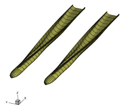
The hull panelmesh of the proposed semi-SWATH design is shown in Fig. 3. The hull geometry is the outcome of a hydrodynamic shape optimization process, as described by Vernengo et al. (2015) , aimed at reducing both the total resistance in calm water and vertical accelerations at the main deck. The selected hull is one of the so-called best Pareto designs among optimization solutions and is the best trade-off in terms of both objective functions.
|
| Fig. 3 Panel mesh of the semi-SWATH design used for the BEM computations |
The hull has quite classic fast catamaran U-shaped stern transverse sections that become SWATH-like in its forward portion, as seen from Fig. 3 characterized by submerged hull and strut sections; starting from about 1/3 of its length from the stern, the waterline becomes narrower and assumes a wedge shape. The volume is then recovered in the lower portion of the hull, which ends in a bulbous bow.
These charactizing geometric elements of the selected hull should allow a ship to possess the hydrodynamic qualities of two parents. Thus, hydrodynamic shape optimization has been used to tune the balance between pros and cons arising by this combination.
The free-surface panel mesh and domain arrangement are shown in Fig. 4. This mesh is made up of three patches: the outer free surface of the hull, inner free surface between the two demi-hulls, and transom wakes behind them. The free-surface domain extends for 80% of the length between perpendiculars, LBP, forward of the hull (SForw), for twice the LBP after it (SAft), and forone LBP aside it (SLat). The same free-surface panel mesh arrangement is used for both hulls.

|
| Fig. 4 Free-surface mesh and domain arrangement for the BEM computations |
Both the hull and free-surface panel mesh configurations (i.e., the number of elements and their distribution) have been selected as a result of a preliminary mesh sensitivity analysis study.
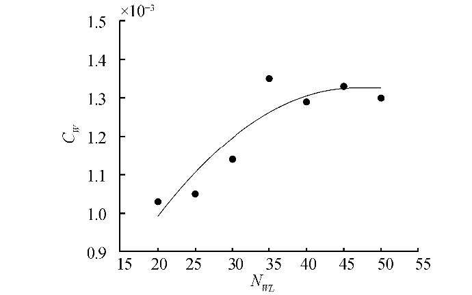
Specifically, starting from a coarse configuration, the number of elements on the hull and free surface is increased until convergence on the wave coefficient value is reached. An increasein the number of mesh panels usually improves the accuracy of the result;however, this requires a higher computational time. Hence, the configuration with the lowest number of elements at convergence is selected for the numerical study (i.e., the faster settings withadequateaccuracy).
Fig. 5 shows an example of this preliminary study for the semi-SWATH at Fn=0.5. The number of elements of the free-surface mesh close to the hull waterline, NWL, is changed from 20 to 50; this is one of the most relevant parameters of the free-surface mesh that strongly affects the overall number of panels. The relative error between following points is negligible as the parameter becomes higher than 40;thus, convergence on the control variable is reached. Then, this value is selected for further computations.
|
| Fig. 5 Example of free-surface mesh sensitivity analysis with respect to the wave resistance coefficient |
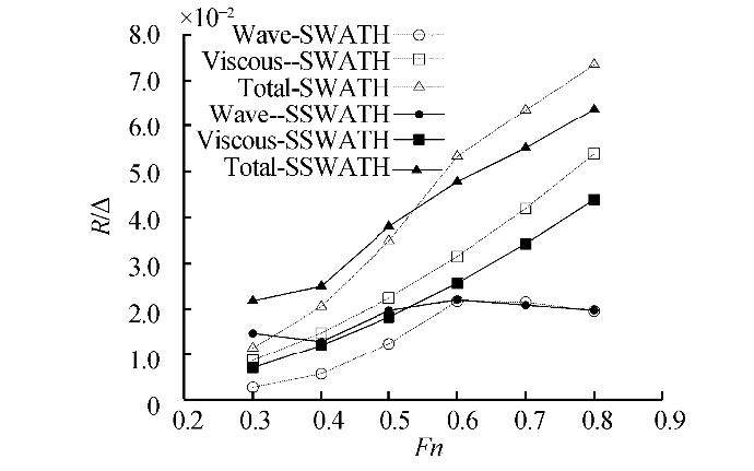
Results of the resistance performance comparison over a wide range of Froude number, i.e., from 0.4 to 0.8, are shown in Fig. 6. The viscous resistance, RV, is computed by the following equation:
$${R_V} = {R_F} (1 + k) $$
(6)
|
| Fig. 6 Swath (empty marker) and semi-SWATH (filled marker) resistance over displacement comparison. Wave, viscous, and total resistance are represented by circles, squares, and triangles, respectively |
The lowest wave resistance achieved by the SWATH in the relatively lower range of Froude number is essentially becauise of the relatively smaller waterplane area, which is intrinsic for this design. In a relatively higher speed range (Fn>0.6), the two wave resistances become comparable, showing relatively slightly lower values for the semi-SWATH design.
Considering the total resistance, the semi-SWATH outperforms the conventional SWATH design as the Froude number exceeds the value of about 0.55, achieving a relative reduction greater than about 14%.
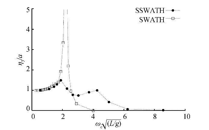
3.2 Seakeeping responses in regular head wavesOnly head waves are considered for the proposed seakeeping comparative analysis. The performance comparison is performed in terms of heave and pitch motion RAOs. Because the interest is focused on the seakeeping behaviors of the hull, the performances of bare hulls are compared, thus excluding any stabilizer fin effect.
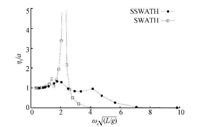
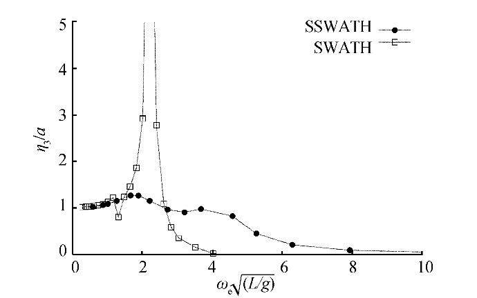
Heave responses for the two hulls are shown in Figs. 7-11 for Froude number of 0.4-0.8, respectively. Figs. 12-16 show pitch responses over the same Froude number range. All RAOs are shown against the non-dimensional encounter frequency.
|
| Fig. 7 Swath (empty squares) and semi-SWATH (filled circles) heave RAO comparison, Fn=0.4 |
|
| Fig. 8 Swath (empty squares) and semi-SWATH (filled circles) heave RAO comparison, Fn=0.5 |
|
| Fig. 9 Swath (empty squares) and semi-SWATH (filled circles) heave RAO comparison, Fn=0.6 |
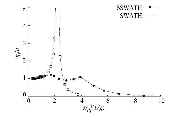
|
| Fig. 10 Swath (empty squares) and semi-SWATH (filled circles) heave RAO comparison, Fn=0.7 |
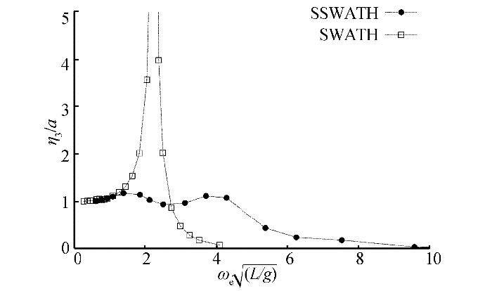
|
| Fig. 11 Swath (empty squares) and semi-SWATH (filled circles) heave RAO comparison, Fn=0.8 |
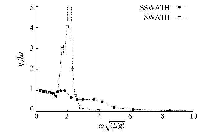
|
| Fig. 12 Swath (empty squares) and semi-SWATH (filled circles) pitch RAO comparison, Fn=0.4 |
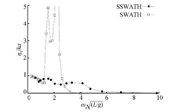
|
| Fig. 13 Swath (empty squares) and semi-SWATH (filled circles) pitch RAO comparison, Fn=0.5 |
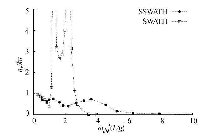
|
| Fig. 14 Swath (empty squares) and semi-SWATH (filled circles) pitch RAO comparison, Fn=0.6 |
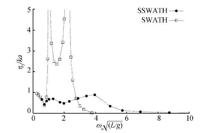
|
| Fig. 15 Swath (empty squares) and semi-SWATH (filled circles) pitch RAO comparison, Fn=0.7 |
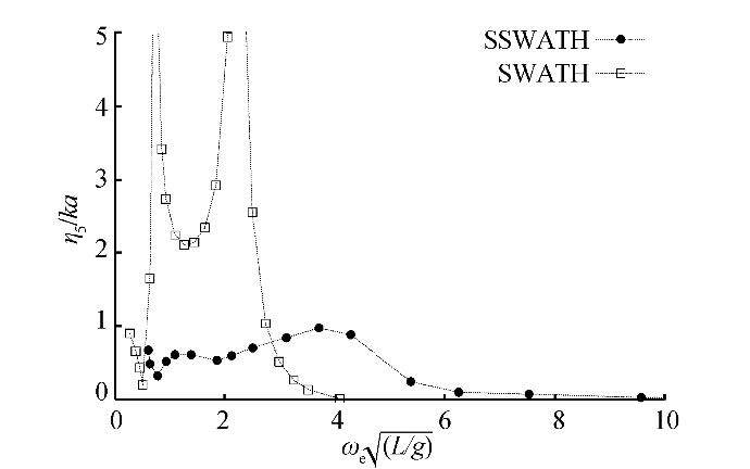
|
| Fig. 16 Swath (empty squares) and semi-SWATH (filled circles) pitch RAO comparison, Fn=0.8 |
The SWATH heave and pitch RAOs show higher peaks (even more than one) of the response in the range of the relatively lower encounter frequencies. The double-peaked response is characteristic of this type of hull, as reported by Dallinga (1990) , Papanikolaou et al. (1991) , and Brizzolara et al. (2013) . In the SWATH hull the double peak is already present in the responses of the isolated demi hull and, according to this result, one can observe that it is due to the demi hull form rather than to some interference effects of the waves generated in between the two demi-hulls. This is verified in Fig. 17, which shows the heave response of the SWATH at Fn=0.5, for two separations, i.e., s/L=0.4 and s/L=∞;the latter corresponds to an isolated demi-hull response. The two RAO curves are very close to each other and reveal the double-peaked shape. The presence of the two peaks should be because of possible different effects of the fraction of exciting forces acting on struts and submerged hulls at different wavelengths.
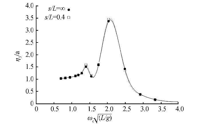
|
| Fig. 17 Comparison of the SWATH heave RAO at Fn=0.5 for two demi-hull separations, s/L=0.4 (empty squares) and s/L=, i.e., isolated demi-hull (filled circles) |
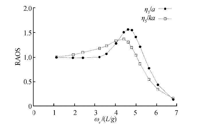
Forcomparison, heave and pitch RAOs of a fast conventional catamaran obtained from Bruzzone and Gualeni (2002) are shown in Fig. 18. Here, we are only interested in the trends of responses because the catamaran is characterized by different hull form dimensions and geometric parameters compared to the other two presented hulls.
|
| Fig. 18 Catamaran heave (filled) and pitch (empty) RAOs, Fn=0.5 (Bruzzone and Gualeni, 2002) |
Regarding the corresponding heave response of the semi-SWATH, the trend is in between two parent hulls. It keeps the double peaked RAO as the SWATH but has lower values with respect to it. The lower peak resembles SWATH behaviors due to the combined effect of the forward shape similar to a SWATH even though the afterward shape is similar to a catamaran. The position of the peak of the semi-SWATH at higher frequencies roughly corresponds to that of the catamaran. The same observations are also valid for the pitch response.
As a general behavior, compared with the SWATH responses, the peaks of the semi-SWATH responses are damped out in the range of the relatively lower non-dimensional encounter frequencies or for higher wavelengths. As the encounter frequency increases (${{\rm{\omega }}_{\rm{e}}}\sqrt {{\raise0.5ex\hbox{$\scriptstyle {\rm{L}}$} \kern-0.1em/\kern-0.15em \lower0.25ex\hbox{$\scriptstyle {\rm{g}}$}}} > \sim 3$ corresponding to ${\raise0.5ex\hbox{$\scriptstyle \lambda $} \kern-0.1em/\kern-0.15em \lower0.25ex\hbox{$\scriptstyle {\rm{L}}$}} \cong 2$) the SWATH RAOs smoothly approach zero, while both the semi-SWATH heave and pitch responses show a small hump. The value of this hump corresponds to another peak for relatively lower wavelengths and is close to or below unity.
4 ConclusionsThe performances of a new semi-SWATH design have been analyzed and compared with those of a conventional SWATH ship. The resistance analysis highlights a limited Froude number (Fn~0.55) after which the semi-SWATH overcomes the performances of a conventional competitor. Regarding seakeeping behaviors, the SWATH design shows relatively higher values of the peaks of both heave and pitch responses, which are drastically damped out by the new hull. This occurs in the frequency range where the SWATH has significant responses. The response of the semi-SWATH is distributed over a wider range of frequencies. At higher frequencies, it resembles that of the high-speed catamaran.
The proposed semi-SWATH hence represents a valuable alternative to conventional SWATH, exploiting the benefits of being a crossover design between SWATH and fast catamarans and achieving good performances with respect to both resistance and seakeeping.
Further hydrodynamic studies will involve the evaluation of viscous effects on the resistance performance and extension of the seakeeping analysis in irregular waves considering characteristic wave spectra.
| Armstrong T, Clarke T, 2009. On the effect of hull shape on the performance of some existing high-speed ferries. 10th International Conference on Fast Sea Transportation, FAST09, Athens, Greece. |
| Brizzolara S, 2004. Parametric optimization of SWAT-hull forms by a viscous-inviscid free surface method driven by a differential evolution algorithm. Proc. 25th Symp Naval Hydrodyn, St John's, Canada, National Academies Press, 5, 1-18. |
| Brizzolara S, Bonfiglio L, Seixa De Medeiros J, 2013. Influence of viscous effects on numerical prediction of motions of SWATH vessels in waves. Ocean Systems Engineering, 3(3), 219-236. DOI: http://dx.doi.org/10.12989/ose.2013.3.3.219 |
| Brizzolara S, Bruzzone D, Cassella P, Scamardella I, Zotti I, 1998. Wave resistance and wave pattern for high speed crafts;validation of numerical results by model tests. Proc. 22nd Symp Naval Hydrodyn, Washington DC, USA, 69-83. |
| Brizzolara S, Gaggero S, 2006. An integrated tool for concept and final design of optimum SWATH-hull forms. Proceedings on Int Conf of Ship and Shipping Research(NAV), Genova, Italy, 2006. |
| Brizzolara S, Vernengo G, 2011a. Automatic computer driven optimization of innovative hull forms for marine vehicles. 10th WSEAS International Conference on Applied Computer and Applied Computational Science, ACACOS'11, 273-278. |
| Brizzolara S, Vernengo G, 2011b. Automatic optimization computational method for unconventional S.W.A.T.H. ships resistance. International Journal of Mathematical Models and Methods in Applied Sciences, 5(5), 882-889. |
| Bruzzone D, 1994. Numerical evaluation of the steady free surface waves. CFD Workshop, Ship Res. Inst., Tokyo, I, 126-134. |
| Bruzzone D, 2003. Application of a Rankine source method to the evaluation of motions of high speed marine vehicles.Proceedings of the 8th International Marine Design Conference, Athens, Gereece, Ⅱ, 69-79. |
| Bruzzone D, Gualeni P, 2002. Numerical prediction of high speed catamaran behaviour in waves. 3rd International Euro-Conference on High-Performance Marine Vehicles, HIPER'02, Bergen, Norway. |
| Couser PR, Molland AF, Armstrong NA, Utama IKAP, 1997. Calm water powering prediction for high speed catamarans.Proceedings of the 4th International Conference on Fast Sea Transportation, FAST'97, Sydney, Australia. |
| Dallinga RP, 1990. Seakeeping characteristics of SWATH vessels.Marine and Offshore Technology, Schip en Werf, MARIN, Ocean Engineering Division, Wageningen, The Netherlands, 267-275. |
| Holloway DS, 1998. A high froude number time domain strip theory applied to the seakeeping of semi-SWATHs. PhD Thesis, University of Tasmania, Hobart, Australia. |
| Kallio JA, 1976. Seaworthiness characteristics of a 2900 tons small waterplane area twin hull(SWATH). David W. Taylor Naval Ship Research and Development Center, Ship Performance Department, SPD-620-03, Maryland. |
| Kring D, Sclavounos PD, 1995. Numerical stability analysis for time-domain ship motion simulations. Journal of Ship Research, 39(4), 313-320. |
| Molland AF, Wellicome JF, Temarel P, Cic J, Taunton DJ, 2000.Experimental investigation of the seakeeping characteristics of fast displacement catamarans in head and Oblique Seas.Transactions RINA, 143, 78-97. |
| Papanikolaou A, Zaraphonitis G, Androulakakis M, 1991.Preliminary design of a high-speed SWATH passenger/car ferry.Mar Technol, 28(3), 129-141. |
| Sclavounos PD, Borgen H, 2004. Seakeeping analysis of high-speed monohull with a motion control bow hydrofoil.Journal of Ship Research, 48(2), 77-117. |
| Shack C, 1995. Research on semi-SWATH hull form. 3rd International Conference on Fast Sea Transportation, FAST95, Lübeck-Travemünde, Germany, 1, 527-538. |
| Vernengo G, Brizzolara S, Bruzzone D, 2015. Resistance and seakeeping optimization of a fast multihull passenger ferry. Int J Offshore and Polar Eng, IJOPE, 25(1), 1-9.(ISSN 1053-5381). |
| Zaraphonitis G, Grigoropoulos G, Morkoyiunnis D, 2009. On the resistance prediction of high-speed semi-SWATH hull forms. 13th Congress of Intl. Maritime Assoc. of Mediterranean IMAM 2009, Istanbul, Turkey, 12-15. |


