2. GE Oil & Gas, Houston, TX, USA
1 Introduction
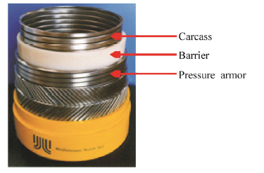
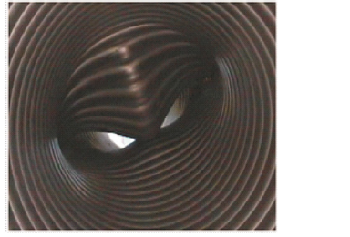
An unbonded flexible pipe typically comprises a number of concentric metallic and thermoplastic layers, as shown in Fig. 1. The component layer is designed to provide a specific structural function. For example, the innermost interlocked carcass layer gives the pipe its collapse resistance, whilst the adjacent and extruded polymer layer provides a sealed conduit for the conveyed fluid. The pressure armor layer is designed to resist the bore pressure. For conservatism, a worst case collapse scenario called wet collapse is assumed where the outside shield is breached and the annulus of the pipe is flooded. As a result, the external hydrostatic pressure acts directly on the barrier layer underneath the pressure armor layer. Tests showed that collapse occurs when the carcass buckles inside the pressure armour layer, which typically causes subsequent buckling of the pressure armour layer as shown in Fig. 2. The other layers are insignificant to the collapse capacity of flexible pipe.
Due to the complexity of the interactions between the layers, most studies related to collapse are limited to finite element methods, such as Lu et al.(2008) and Neto and Martins(2011), or a combination of analytical method and FEA Model, for example, Tang et al.(2012) and LoureiroJr and Pasqualino(2012). Theoretical analysis is rare. In this investigation an analytical model was developed considering only three layers, i.e. the carcass, barrier and pressure armor layers. Since the carcass and pressure armor layers are wound almost circumferentially, both layers are idealized as solid uniform rings. An equivalent width of the corresponding ring is incorporated to account for the fraction of materials that fill each layer. The barrier and pressure armor layers were considered as two series of springs to provide support to the carcass against buckling. Structural equilibrium equations were used to analyze the contact pressure between the carcass and barrier. A moment-curvature equation was applied repeatedly in its differential form to all three layers as an analytical solution for assessing the collapse strength of the carcass.
|
| Fig. 1 Unbonded flexible pipe |
|
| Fig. 2 Wet collapse in test |
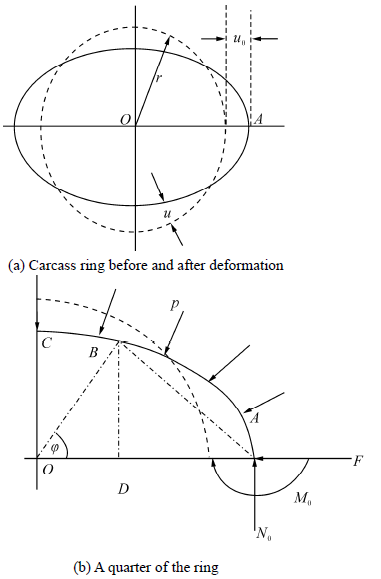
Under external pressure the circular carcass ring with a radius of r is buckled into a slightly-deformed elliptical shape is shown in Fig. 3 (a). The dash line represents the initial circular ring and the solid line represents its deformed shape. Let u denote the small radial displacement of a section and be positive when the section moves towards the centre of the ring. Under the assumption the displacement u0 at the cross section A is negative.
|
| Fig. 3 Outline of carcass collapse modeling |
As the structure and its loads are both simplified geometrically symmetric, only a quarter of the structure is considered as shown in Fig. 3 (b). The action of the removed lower part of the ring on the upper part of the section A can be described by a force N0 and a moment M0. It is assumed that point contact happens between the carcass and pressure armor layers during buckling. The reaction from the pressure armor layer is represented by force F. Next, the bending moment at any part of section B satisfies

Considering the triangle OAB, we have


Substituting this expression into Eq.(1) and assuming that displacement is very small in comparison with the radius of the ring so that the squares of u and u0 can be neglected, the bending moment is then approximated by

To simplify the problem, we assume that the bending moment made by F has a linear distribution in terms of radial displacement u. Under this assumption, the last term of Eq.(2)is approximated by

Test results showed that the pressure armor layer enhances the collapse strength by resisting deflection and subsequent collapse of the underlying structure and acts as a spring to provide external support to the underlying structure. However, its thickness variation does not significantly affect the collapse performance. In addition, Hooke’s law reveals that the surface contact pressure of two elastic bodies is proportional to its radial displacement. As a result, Eq.(3)is rewritten as

By use of a general equation of circular bar derived by Timoshenko(1941), the differential equation of the deflection curve of the ring is

Substituting Eq.(4)into Eq.(2) and further into Eq.(5) and performing some algebraic operations results in

The general solution of Eq.(6)is given by the following:


From symmetry at sections A and C, it follows that and

By applying these boundary conditions to Eq.(7), the critical pressure is obtained:

It can be seen from Eq.(9)that the pressure armor layer plays a role somewhat equivalent to adding a value to the first term at the right h and side of the equation. Hence, pressure armor layer enhances wet collapse strength.
As a concentric tube we now discuss the interaction between carcass and barrier. When uniformly distributed hydrostatic pressure p acts on the surface of the barrier layer, the contact pressure on the surface of the carcass ring is given by the following equation:


When combining Eqs.(9) and (10)results in the modified critical pressure of the carcass layer the following is obtained:

For a flexible pipe with its annulus flooded using Eq.(12), which calculates the wet collapse strength is further rewritten as

The barrier and pressure armor act like two springs connected in series. It is assumed that the displacement of the pressure armor is described approximately by Timoshenko(1941):

Substituting Eq.(14)into Eq.(5)results in the change of the curvature of the ring, expressible as

Therefore, the potential energy is given by

It then follows from a principle of minimum potential energy that

Based on this, we obtain

Similarly, for barrier layer we have

They are further rewritten as


The critical pressure of carcass with pressure armor aided against buckling is finally given by

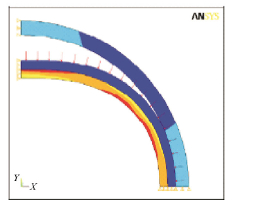
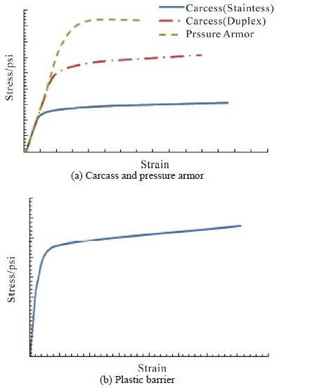
The finite element collapse model was developed by using the finite element analysis software ANSYS. Similar to the analytical model discussed above, the geometry is simplified in the FE model, where the carcass and pressure armor layer are modeled as solid uniform ring with the same wall thickness as the design or as-built one of each layer. A st and ard two dimensional structural element is used for each of the three layers considered in the model. Only a quarter of the structure is modeled as illustrated in Fig. 4. Symmetry boundary conditions are applied on both ends of the quarter model. The barrier layer is modeled as a plane strain problem, while the carcass and pressure armor layers are modeled as a plane stress problem. Nonlinear properties of both metallic and polymer materials are considered in the finite element model. The typically used stress-strain curves are depicted in Fig. 5 for metallic and polymer materials, respectively. The hydrostatic pressure is applied on the outer surface of the barrier. The applied pressure is increased incrementally until collapse occurs.
The FEA Model was calibrated against the mean of the test collapse data with the ideal nominal size of the pipe and the nominal sizes of the carcass, barrier and pressure armour layers. The calibrated model was then used to predict the collapse strength of the pipe design based on the worst combination of the relevant manufacture tolerances such as the largest structural imperfection, largest carcass inner diameter, minimum formed thickness and minimum fraction fill of carcass. The initial structural imperfection with ovality is introduced to the internal carcass layer. The initial ovalities are representative of typical measurements taken during the manufacturing process. In this investigation, a value of 0.001 was used for all the simulations.
In order to investigate the role of the pressure armor layer in pipe collapse strength and to verify the theoretical model developed in this study, a modified model that has the pressure armor layer is removed and is also developed for this purpose.
|
| Fig. 4 Flexible pipe wet collapse finite element model |
|
| Fig. 5 Stress-strain curves |
The analytical model developed was used to predict collapse strength of a flexible pipe under external hydrostatic pressure for a total of eight different pipes. These pipes have different diameters and each layer has different thickness and geometry. GE Oil & Gas has conducted a series of collapse tests over the last several decades with variable pipe inner diameters(IDs)ranging from 4 inches up to 16 inches. More details can be found in the reference by Lu et al.(2008). For confidentiality reasons the pipe dimensions and the experiment data are not provided in this study. In order to compare with the FEA model, both analytical and FEA models were performed by using the same geometric and material parameters. The ratio of the mean radius(r)to the thickness(t)of carcass ranges from 10 to 21, the ratio of the mean radius(rB)to the thickness(tB)of barrier is from 9 to 28 and the ratio of the mean radius(rL)to the thickness(tL)of pressure armor is from 10 to 29. The two parameters f and fL used in Eqs.(17) and (18) and in the FEA model are the fraction fills of the material for the carcass and pressure armor layers, respectively.
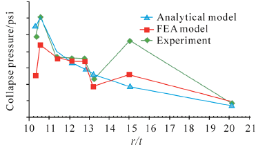
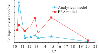
The predicted collapse pressure by the analytical model, FEA model and full-scale test are shown in Figs. 6 and 7. Fig. 6 shows the total collapse pressure against the ratio of mean radius to thickness of carcass(r/t). Numerical tests revealed that when r/t<10, the collapse capacity predicted by the analytical model is overestimated, whereas the FEA model is conservative. Fig. 7 presents the collapse strength contributed by pressure armor layer only, contributing 5% to 25% of the total collapse strength by the analytical model and 5% to 37% by the FEA model. Eq.(11a)was used to calculate β and Eq.(17b)used for parameters kB and kL.
|
| Fig. 6 Collapse pressure of pipe against the ratio of mean radius and thickness of carcass(r/t) |
|
| Fig. 7 Collapse strength contributed by pressure armor layer against the ratio of mean radius and thickness of carcass(r/t) |
As mentioned in the introduction section, the wet collapse assumes that the external hydrostatic pressure acts directly on the barrier layer rather than the outside pressure armor layer. When the carcass layer starts to deform as shown in Figs. 2 and 4, the pressure armor layer will provide support outside the barrier layer by resisting ovalization from the two sides. The strength of support depends on the pipe ID, the sizes and mechanical properties of the relevant three layers.
In general, for a single layer pipe the collapse pressure is expected to decrease with increasing r/t. However, for flexible pipe wet collapse, when the pipe ID increases, the critical pressure decreases and so does the thickness of the barrier. Inversely, when the thickness of carcass increases, the critical pressure increases and so does the thickness of pressure armor. It is noted that Figs. 6 and 7 are plotted against the ratio of mean radius and thickness of carcass(r/t)C rather than the ratio of mean radius and thickness of pressure armor(r/t)PR or the ratio of mean radius and thickness of barrier(r/t)B. The collapse strength fluctuations instead of decreasing with the increasing of(r/t)C are mainly due to the variations of(r/t)PR and (r/t)B. The enhancement of the pressure armor to the wet collapse strength as shown in Fig. 7 is a major contribution to the fluctuation of the total collapse pressure presented in Fig. 6. It should be emphasized that the collapse strength contributed by pressure armor layer was obtained by taking the difference of the calculated critical pressures between the three-layer and two-layer FEA models or Eq.(18)with and without the last term for the analytical model.
The pressure armor-aided collapse strength calculated by the FEA model, which is presented in Fig. 7 deviates from the prediction of the analytical model. Further investigation may be required for parameters kB and kL in Figs.(17a) and (17b)during the calibration process as polymer behavior may change under high pressure conditions. In terms of the FEA model the effects of some parameters on pipe collapse strength such as the friction between layers, the polymer creep behavior and the thickness reduction of barrier due to gap span between carcass and barrier under high hydrostatic pressure are needed to do further investigation.
For a smaller r/t ratio, for example less than 10, a greater discrepancy was observed between the model and test results. In addition to the manufacturing forming process(cold work, residual stress, etc.) and manufacturing tolerances, the potential distributing hoop stress and strain over wall thickness may also result in a discrepancy between the model and reality.
In reality, due to manufacturing tolerances, the radii and thicknesses of all component layers are not exactly the same as the nominal ones given by the pipe design. The real collapse resistance is subjected to the actual as-built sizes of these layers. For the same reason, these layers always inherit ovality. The ovality behaves as a structural imperfection and reduces the collapse resistance significantly. It is also understood that a certain amount of cold work will inevitably be induced into the formed carcass and pressure armor layers as a result of the manufacturing process. These phenomena are observed from both the scattered test data and the model analysis so further investigation is still required for better underst and ing the interaction between carcass, barrier and pressure armor layers.
5 Conclusions1)The contact mechanism between the pressure armor layer, barrier and inner carcass can affect the buckling capacity of the flexible pipe.
2)The model is suitable for large ratio of the mean radius to the thickness of carcass(r/t), i.e. thin wall pipe(for example r/t is greater than 10). This is consistent with a model assumption of a thin wall pipe. 3)For very large r/t(for example, r/t>18), the predicted collapse pressure by the analytical model is conservative.
4)It is encouraging that the presented model captures the variation tendency of the pipe collapse strength with respect to the increase in r/t ratio. It should be noted that the theoretical results presented in this paper are based on the nominal parameters of the pipe designs. Improvement in the theoretical prediction is anticipated by considering the pipe as built sizes including ovality and material properties.
5)The collapse capacity of a flexible pipe is influenced by many factors such as the pipe structure, the material used for each layer and manufacturing tolerances. This also means that tests results can return a degree of scatter from model predictions.
As mentioned earlier, the collapse strength of a flexible pipe is influenced by many factors. From this point of view, the results presented in this investigation are very limited. The imperfection with an initial ellipticity is expected to be taken into account theoretically in further works. Besides, in the oil and gas industry, a pipe is most likely to be subjected to high hydrostatic pressure in deep water conditions and under such conditions the materials of the pipes are stressed to collapse in the plastic range. Therefore, the elastic equation may need to incorporate a revised equivalent modulus(Timoshenko, 1941; Clinedinst, 1939), which could be considered during calibration against tests.
| Clinedinst WO (1939). A rational expression for the critical collapsing pressure of pipe under external pressure. API Drilling and Production Practice, 383-420. |
| Loureiro Jr WC, Pasqualino I (2012). Numerical-analytical prediction of the collapse of flexible pipes under bending and external pressure. Proceedings of the ASME 31th International Conference on Ocean, Offshore and Arctic Engineering, Rio de Janeiro, Brazil.. DOI: 101115/OMAE2012-83476 |
| Lu J, Ma F, Tan, ZM, Sheldrake T (2008). Bent collapse of an unbonded rough bore flexible pipe. Proceedings of the ASME 27th International Conference on Ocean, Offshore and Arctic Engineering, Estoril, Portugal. DOI: 10.1115/OMAE2008-57063 |
| Neto AG, Martins CA (2011). flexible pipes: influence of pressure armor in the wet collapse resistance. Proceedings of the ASME 30th International Conference on Ocean, Offshore and Arctic Engineering, Rotterdam, the Netherlands. DOI: 10.1115/OMAE2011-49105 |
| Tang M, Yan J, Wang Y (2012). collapse estimation of interlocked armor of flexible pipe with strain energy equivalence. Proceedings of the ASME 31th International Conference on Ocean, Offshore and Arctic Engineering, Rio de Janeiro, Brazil. DOI: 10.1115/OMAE2012-83705 |
| Timoshenko S (1941). Strength of materials, part ii, advanced theory and problems. 2nd Edition, D Van Nostrand Company, Inc. |
| Young WC, Budynas RG (2002). Roark's Formulas for Stress and Strain. Seventh Edition, McGraw-Hill Professional. |


