2. 哈尔滨工程大学 船舶工程学院,黑龙江 哈尔滨 150001
2. College of Shipbuilding Engineering, Harbin Engineering University, Harbin 150001, China
水下爆炸是威胁船舶生命力的重要因素[1-3],中远场水下爆炸将产生严酷的冲击环境[4 − 5],现代大型船舶设计对于设备抗冲击性能提出了更高要求。高压管道是大型船用汽轮机传递动力的重要组成部分,研究其在冲击载荷作用下的失效特性具有重要意义。
目前,对于船舶管路系统,尤其是高压管道的抗冲击性能评估,已有学者开展了一系列的研究并取得了一定的研究成果,但我国尚未形成成熟的评估方法以及专门、统一的评估标准[6]。王朝[7]基于谱分析法和时域分析法研究了典型管路系统的抗冲击性能。冯麟涵等[8-9]研究了船舶管路在冲击载荷作用下的失效形式以及典型部件对管路系统抗冲击性能的影响。沈中祥等[10]基于对船舶管路系统的抗冲击性能分析设计了一种新型的抗冲击元器件。张瑞雪等[11]基于Ansys/LS-DYNA软件研究了空中爆炸载荷对螺栓法兰管道的动态响应。张义忠等[12]基于Isight软件研究了爆炸冲击载荷作用下高压气瓶及其管道系统抗冲性能优化方法。
本文基于有限元方法,拟针对某新型大功率船用汽轮机[13]高压管道的静态与冲击载荷作用下的承载能力和失效特性进行研究,旨在填补国内船用动力设备高压管道抗冲击性能评估研究空白,为高压管道设计提供参考。
1 高压管道数值模型 1.1 高压管道有限元模型及装配本文采用的高压管道几何模型如图1所示(单位:mm)。

|
图 1 高压管道几何模型 Fig. 1 Geometric model of high pressure pipeline |
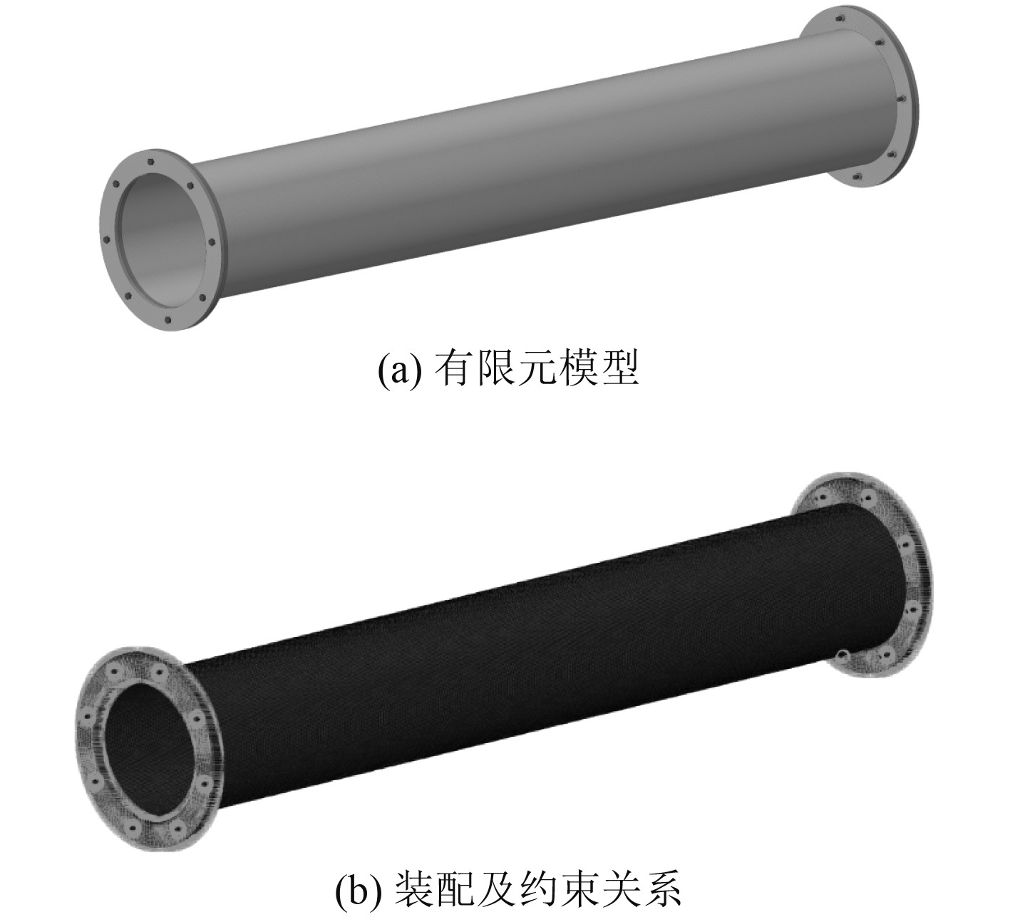
基于HyperMesh软件建立高压管道有限元模型,如图2(a)所示。管道采用壳S4R单元,法兰采用实体C3D8R单元,两者共节点连接。法兰与法兰之间采用螺栓连接。管道内部蒸汽工作压力为0.5 MPa。
|
图 2 高压管道模型 Fig. 2 The model of high pressure pipeline |
法兰与螺帽端面、法兰与螺母端面以及螺栓杆与螺孔内壁等均采用Tie约束,螺栓与螺母之间采用共节点处理,法兰与法兰之间采用接触算法,如图2(b)所示。
1.2 材料模型高压管道各部件材料均采用双线性弹塑性模型,主要材料及静态屈服极限如表1所示。
|
|
表 1 高压管道各部件材料及静态屈服极限 Tab.1 Materials and static yield limits of high pressure pipeline components |
根据塑性动力学理论,材料在高应变率下的屈服极限相较于静态有一定提升,本文基于Cowper-Symonds模型来考虑应变率与屈服应力之间的关系:
| $ \dot \varepsilon = D{\left[ {\frac{{{\sigma _{\mathit{d}}}}}{{{\sigma _{\mathit{y}}}}} - 1} \right]^q}。$ | (1) |
式中:
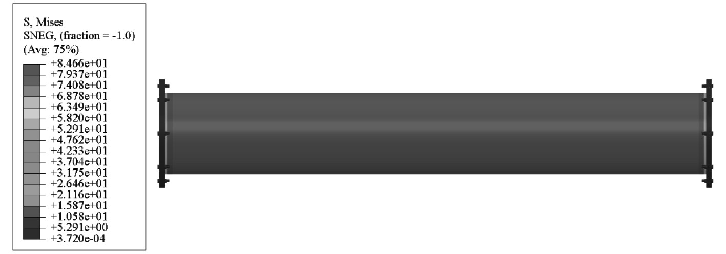
模态计算可验证有限元建模工作的有效性,为后续动力学分析提供参考。将管道一端法兰端面进行刚性固定,另一端不进行任何约束;为模拟管内蒸汽产生的预应力作用,首先采用Abaqus/Standard求解器中的StaticGeneral分析步进行静力分析(开启非线性以保证模态分析中的刚度矩阵发生改变),如图3所示,在此基础上进行Frequency分析步即预应力模态计算。
|
图 3 管内蒸汽产生的预应力 Fig. 3 Pre-stress generated by steam inside the pipe |
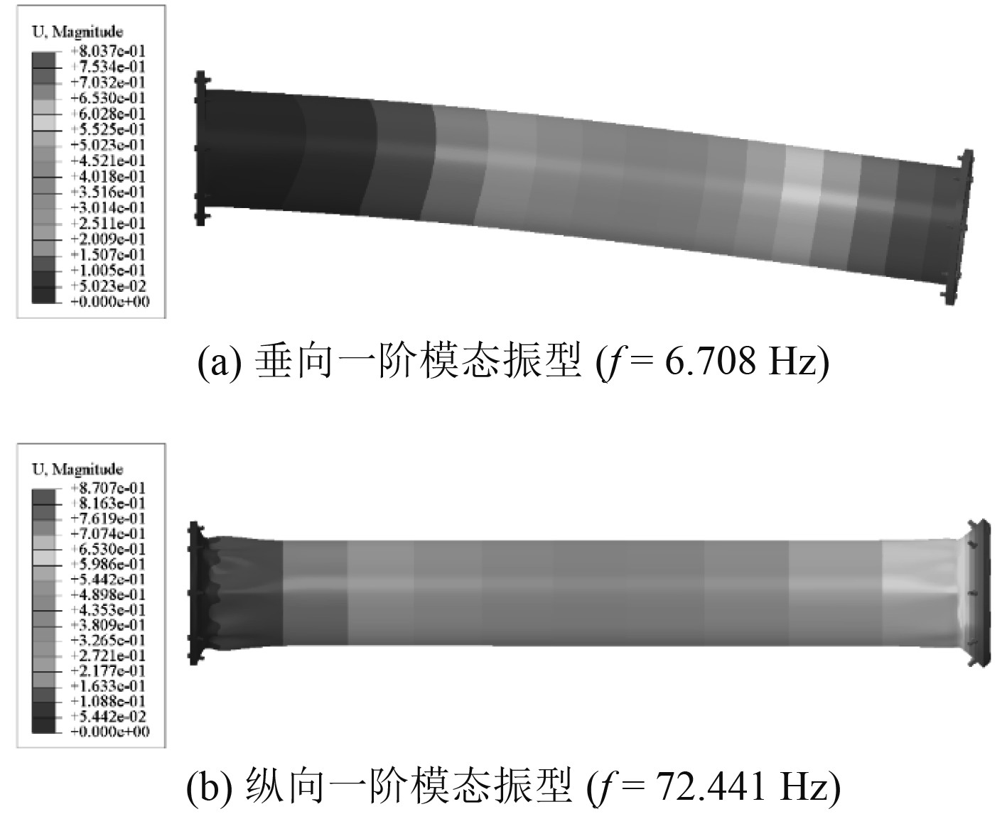
高压管道垂向和纵向一阶模态振型如图4所示。管道垂向弯曲自振周期约为149 ms,纵向压缩或拉伸自振周期约为14 ms。
|
图 4 高压管道的一阶模态振型 Fig. 4 The first-order modal shape of high-pressure pipeline |
将高压管道两端法兰端面处节点耦合至管道中心线参考点处,一端刚性固定,另一端在垂向施加500 mm的强迫位移,管道内壁加载0.5 MPa的均布载荷(在第1个StaticGeneral分析步中进行加载,第2个分析步中作为定常载荷),计算模型如图5所示。

|
图 5 高压管道静态弯曲计算模型示意图 Fig. 5 Schematic diagram of static bending calculation model for high-pressure pipelines |
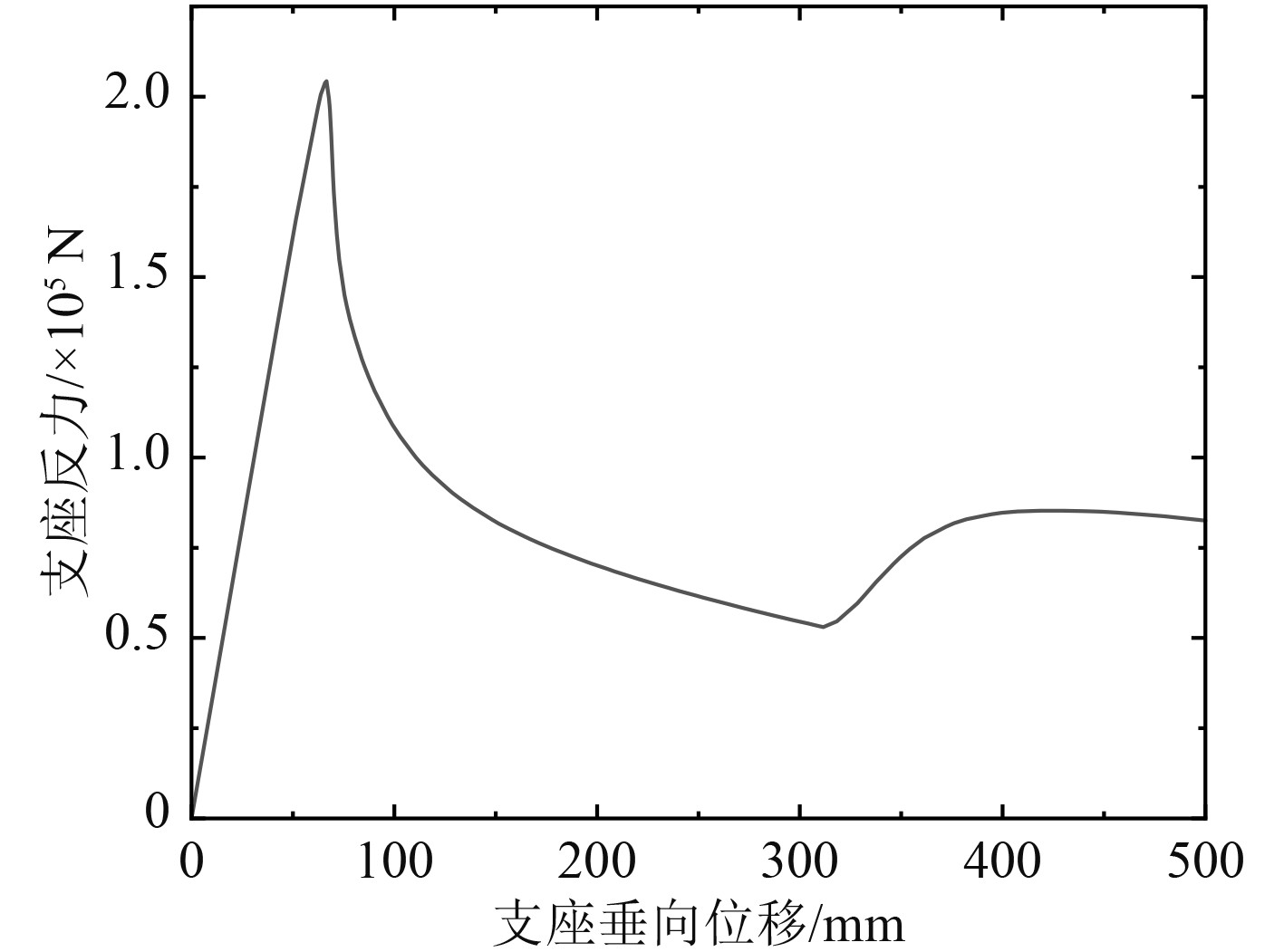
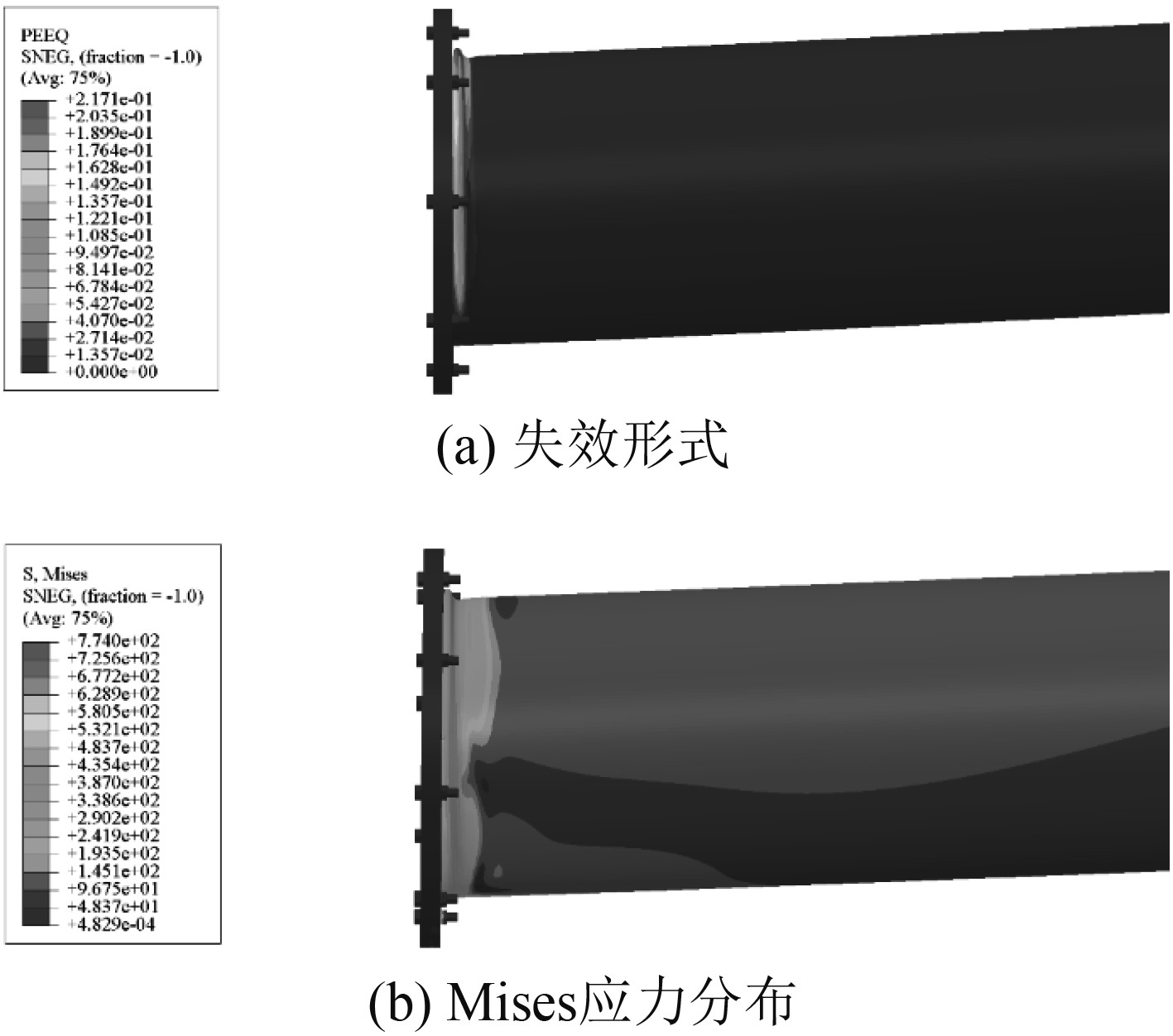
高压管道在静态弯曲载荷作用下的载荷-位移曲线如图6所示。当支座反力增大至约200 kN时,固定端法兰与管道连接处受压一侧首先发生失稳,即丧失承载能力,如图7所示,当支座位移继续加载至约300 mm时,管道已被压溃,管道产生塑性大变形与法兰发生接触从而使支座反力略有增大。
|
图 6 静态弯曲载荷作用下高压管道载荷-位移曲线 Fig. 6 Load displacement curve of high-pressure pipeline under static bending load |
|
图 7 静态弯曲载荷作用下高压管道的响应 Fig. 7 Response of high pressure pipeline under static bending load |
高压管道静态压缩计算模型如图8所示。

|
图 8 高压管道静态压缩计算模型示意图 Fig. 8 Schematic diagram of static compression calculation model for high-pressure pipelines |
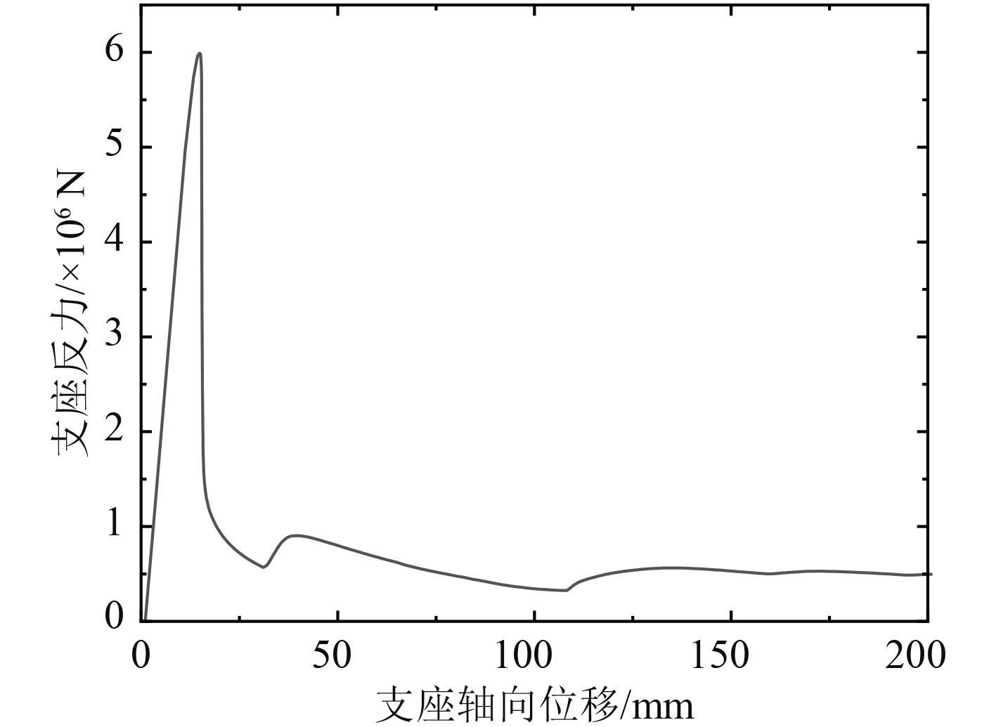
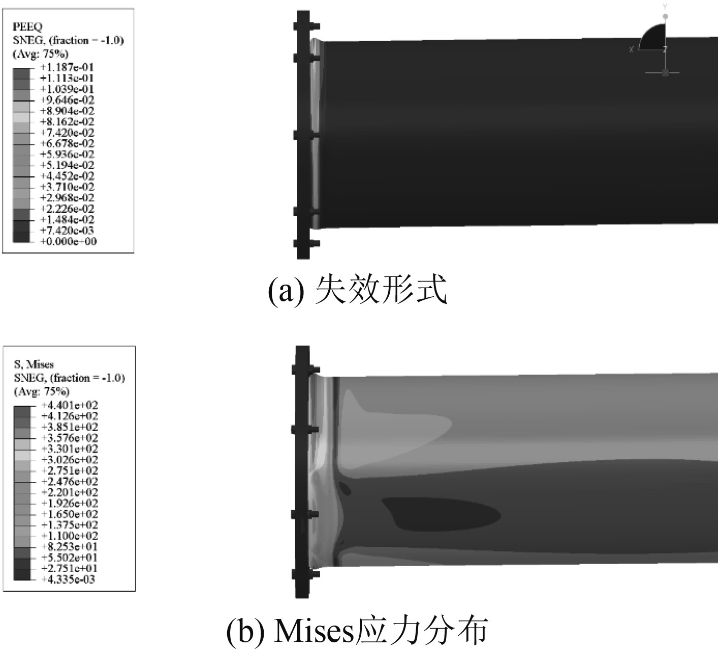
静态压缩载荷作用下高压管道的载荷-位移曲线如图9所示。高压管道受到大约6 000 kN的轴向压缩集中载荷时发生失稳,随后支座反力快速下降,说明高压管道此时已丧失承载能力。失稳部位主要发生在固定端法兰与管道的连接处,如图10所示。相比于受弯状态,在受压状态下高压管道具有更高的承载能力。
|
图 9 静态压缩载荷作用下高压管道载荷-位移曲线 Fig. 9 Load displacement curve of high-pressure pipeline under static compressive load |
|
图 10 静态压缩载荷作用下高压管道的响应 Fig. 10 Response of high pressure pipeline under static compression load |
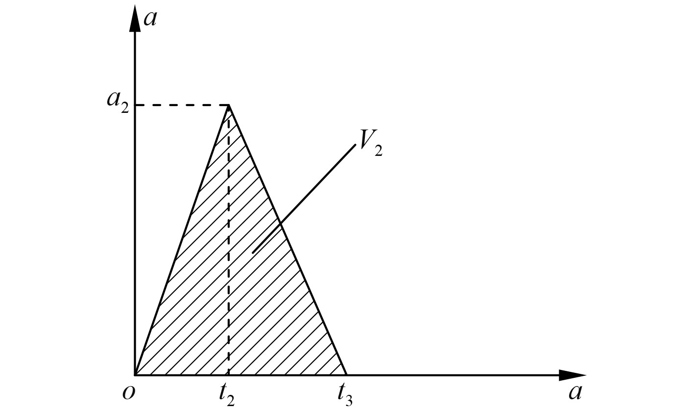
冲击谱等效时域加速度载荷采用一个正三角波的形式,如图11所示。将Abaqus/Standard求解器的计算结果(管道预应力加载)以预定义场的形式输入至Abaqus/Explicit求解器,在进行DynamicExplicit分析步求解过程中管内蒸汽压力作为定常载荷。管道一端法兰端面处采用刚性固定边界条件,另一端法兰端面处施加正三角波加速度载荷。总求解物理时间为3t3。
|
图 11 正三角波时历加速度曲线 Fig. 11 Time history acceleration curve of regular triangular wave |
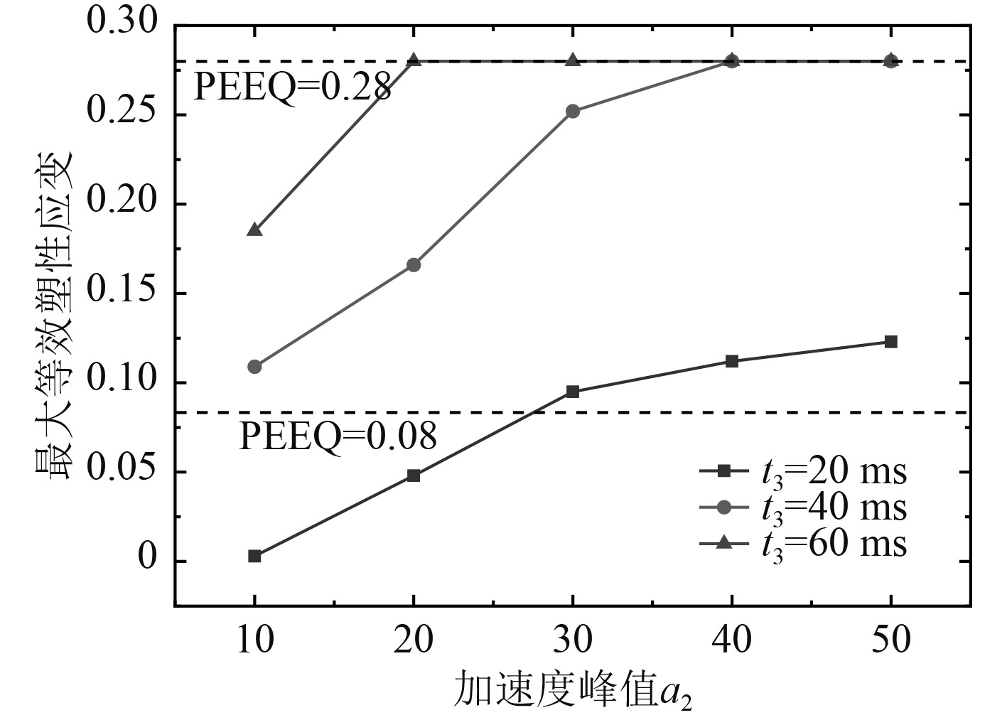
为探究高压管道极限抗冲击能力[15],选取脉宽t3(应小于模态计算结果中自振周期的一半)变化范围为20~60 ms,变化步长为20 ms;加速度载荷峰值a2变化范围为10g~50g,变化步长为10g。以最大等效塑性应变值0.08为失效判定标准,在给定垂向冲击载荷作用下,高压管道的最大Mises应力和等效塑性应变如表2~表4所示。
|
|
表 2 垂向冲击载荷作用下高压管道最大Mises应力和等效塑性应变(脉宽t3 = 20 ms) Tab.2 Maximum Mises stress and equivalent plastic strain of high-pressure pipeline under vertical impact load (pulse width t3=20 ms) |
|
|
表 4 垂向冲击载荷作用下高压管道最大Mises应力和等效塑性应变(脉宽t3 = 60 ms) Tab.4 Maximum Mises stress and equivalent plastic strain of high-pressure pipeline under vertical impact load (pulse width t3=60 ms) |
|
|
表 3 垂向冲击载荷作用下高压管道最大Mises应力和等效塑性应变(脉宽t3 = 40 ms) Tab.3 Maximum Mises stress and equivalent plastic strain of high-pressure pipeline under vertical impact load (pulse width t3=40 ms) |
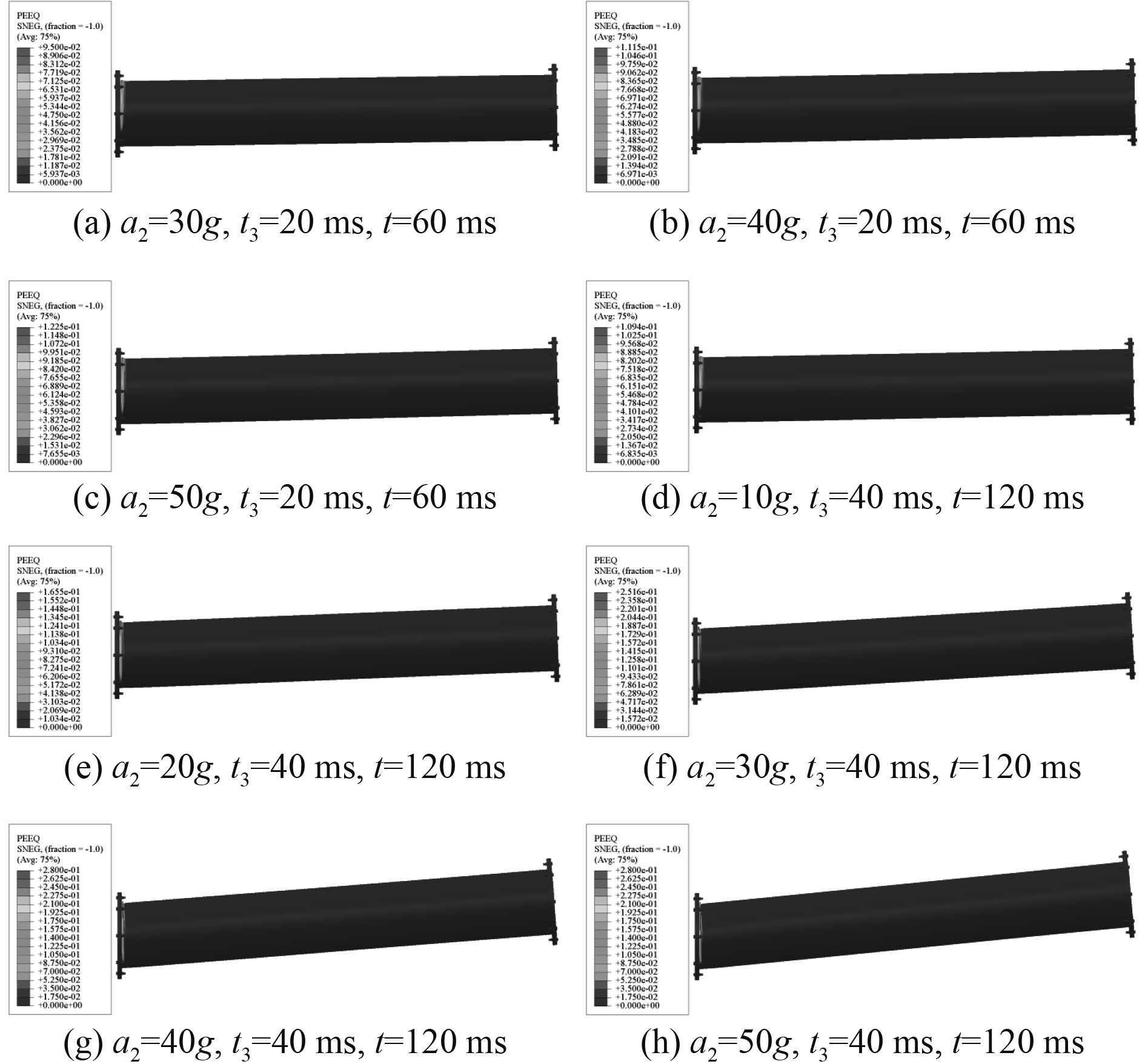
由上述数据可知,高压管道在垂向冲击载荷作用下,最大Mises应力和等效塑性应变随垂向加速度峰值a2和脉宽t3的增大均呈增大趋势,如图12所示。当a2=30g,t3=20 ms时,法兰与管道连接处产生较大的塑性变形,使得管道在管内蒸汽压力的作用下有开裂风险,即引发失效。当a2=40g,t3=40 ms时,等效塑性应变达到断裂应变,高压管道发生断裂失效。高压管道的失效形式如图13所示。管道的最大等效塑性应变大于螺栓和螺母等部件。
|
图 12 不同加速度峰值a2和脉宽t3垂向冲击载荷下管道的最大等效塑性应变 Fig. 12 Maximum equivalent plastic strain of pipeline under vertical impact load with different acceleration peaks a2 and pulse width t3 |
|
图 13 垂向冲击载荷作用下高压管道的失效形式 Fig. 13 Failure forms of high-pressure pipelines under vertical impact load |
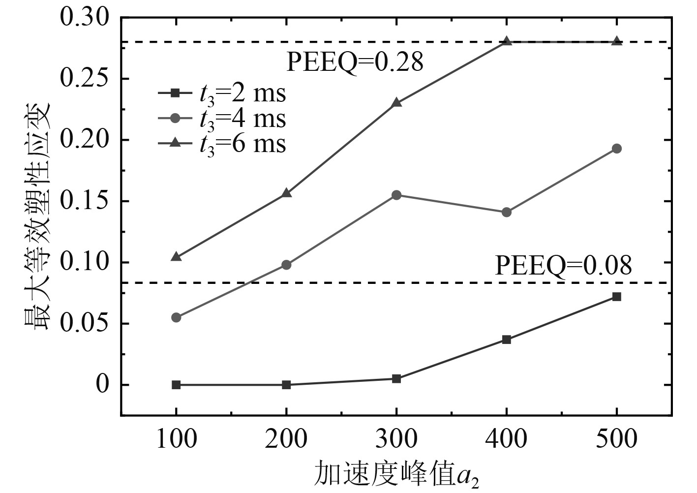
根据预应力模态计算结果,选取脉宽t3变化范围为2~6 ms,变化步长为2 ms,分别对应高频、中频以及低频载荷;加速度载荷峰值a2变化范围为100~500g,变化步长为100g。在给定纵向冲击载荷作用下,高压管道的最大Mises应力和等效塑性应变如表5~表7所示。
|
|
表 5 纵向冲击载荷作用下高压管道最大Mises应力和等效塑性应变(脉宽t3 = 2 ms) Tab.5 Maximum Mises stress and equivalent plastic strain of high-pressure pipeline under longitudinal impact load (pulse width t3=2 ms) |
|
|
表 7 纵向冲击载荷作用下高压管道最大Mises应力和等效塑性应变(脉宽t3 = 6 ms) Tab.7 Maximum Mises stress and equivalent plastic strain of high-pressure pipeline under longitudinal impact load (pulse width t3=6 ms) |
|
|
表 6 纵向冲击载荷作用下高压管道最大Mises应力和等效塑性应变(脉宽t3 = 4 ms) Tab.6 Maximum Mises stress and equivalent plastic strain of high-pressure pipeline under longitudinal impact load (pulse width t3=4 ms) |
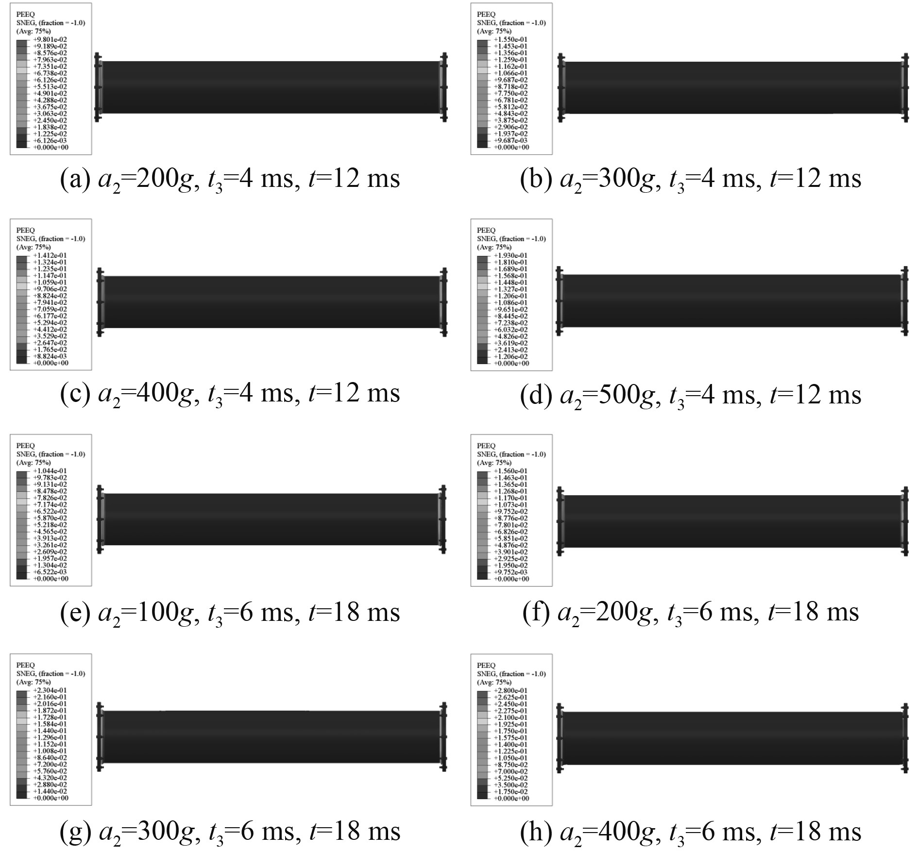
不同加速度峰值a2和脉宽t3下管道的最大等效塑性应变如图14所示,相比于垂向冲击载荷,管道在受到纵向冲击载荷作用时,法兰、螺栓和螺母等部件并未起到有效的承载作用,均在弹性范围内,未发生塑性变形。当a2=200g,t3=4 ms时,高压管道在纵向冲击载荷作用下开始发生失效,当a2和t3继续增大至400g和6 ms时,管道与法兰连接处发生断裂,如图15所示。
|
图 14 不同加速度峰值a2和脉宽t3纵向冲击载荷下管道的最大等效塑性应变 Fig. 14 Maximum equivalent plastic strain of pipeline under longitudinal impact load with different acceleration peaks a2 and pulse width t3 |
|
图 15 纵向冲击载荷作用下高压管道的失效形式 Fig. 15 Failure forms of high-pressure pipelines under longitudinal impact load |
本文基于HyperMesh软件建立高压管道数值模型,在Abaqus软件下基于有限元方法对其在静态和冲击载荷作用下的承载能力与失效特性进行研究,得到以下结论:
1)高压管道的弯曲自振周期明显高于轴向压缩或拉伸的自振周期。
2)高压管道在静态弯曲载荷作用下的承载能力小于在压缩载荷作用下的承载能力,首先发生失稳的部位在管道与法兰连接处。
3)在冲击载荷作用下高压管道的失效形式为法兰与管道连接处在高频载荷下形成的局部塑性大变形以及低频载荷下造成的断裂。
4)相比于受垂向冲击载荷,高压管道在受到纵向冲击载荷作用时螺栓、螺母以及法兰等部件并未起到较强的承载作用,均未发生塑性变形。
| [1] |
ZHANG A M, LI S -M, CUI P, et al. A unified theory for bubble dynamics[J]. Physics of Fluids, 2023, 35: 033323.
|
| [2] |
LIU W-T, ZHANG A M, MIAO X-H, et al. Investigation of hydrodynamics of water impact and tail slamming of high-speed water entry with a novel immersed boundary method[J]. Journal of Fluid Mechanics, 2023, 958: A42.
|
| [3] |
张阿漫, 王诗平, 彭玉祥, 等. 水下爆炸与舰船毁伤研究进展[J]. 中国舰船研究, 2019, 14(3): 1-13. ZHANG Aman, WANG Shiping, PENG Yuxiang, et al. Research progress in underwater explosion and its damage to ship structures[J]. Chinese Journal of Ship Research, 2019, 14(3): 1-13. |
| [4] |
朱锡, 李海涛, 牟金磊, 等. 水下近距爆炸作用下船体梁的动态响应特性[J]. 高压物理学报, 2010, 24(05): 343-350. ZHU Xi, LI Haitao, MOU Jinlei, et al. Dynamic response characteristics of ship-like beam subjected to underwater explosion in near field[J]. Chinese Journal of High Pressure Physics, 2010, 24(05): 343-350. |
| [5] |
CANDIA S D, OJEDA R, REID W, et al. The whipping response of a submerged free-free cylinder due to underwater explosions[J]. Pacific 2017 International Maritime Conference, 2017, 1-8.
|
| [6] |
周心桃, 吴国民, 李德聪. 舰船抗爆抗冲击技术体系探析[J]. 中国舰船研究, 2023, 18(2): 127-139. ZHOU Xintao, WU Guomin, LI Decong. Analysis of naval warship blast and shock resistance technology system[J]. Chinese Journal of Ship Research, 2023, 18(2): 127-139. |
| [7] |
王朝. 典型管路系统抗冲击性能分析方法新型抗冲击元器件设计研究[D]. 镇江: 江苏科技大学, 2013.
|
| [8] |
冯麟涵, 汪玉, 张磊, 等. 舰用典型设备抗冲击能力定量分析[J]. 中国舰船研究, 2011(6): 23−27. FENG Linhan, WANG Yu, ZHANG Lei, et al. Quantitative analysis on shock resistance ability of shipboard equipment[J]. Chinese Journal of Ship Research, 2011(6): 23−27. |
| [9] |
冯麟涵, 韩璐, 闫明, 等. 典型部件对舰船管路系统抗冲击性能影响研究[J]. 振动与冲击, 2020, 39(4): 261-265. FENG Linhan, HAN Lu, YAN Ming, et al. A study on the impact of typical components on the anti-shock resistance of shipboard pipelines[J]. Journal of Vibration and Shock, 2020, 39(4): 261-265. |
| [10] |
沈中祥, 刘寅东, 郑婷婷. 舰艇管路系统抗冲击设计及性能分析[J]. 舰船科学技术, 2017, 39(9): 108-113. SHEN Zhongxiang, LIU Yindong, ZHENG Tingting. Design for shock resistance of piping system of naval vessels and performance analysis[J]. Ship Science and Technology, 2017, 39(9): 108-113. DOI:10.3404/j.issn.1672-7619.2017.05.021 |
| [11] |
张瑞雪, 曲艳东, 于跃, 等. 空爆载荷作用下螺栓法兰管道的动态响应研究[J]. 工程爆破, 2022, 28(1): 26-36. ZHANG Ruixue, QU Yandong, YU Yue, et al. Dynamics response of a bolted flanged pipe joint under air blast load[J]. Engineering Blasting, 2022, 28(1): 26-36. |
| [12] |
张义忠, 王帅, 马天宇. 爆炸冲击载荷下高压气瓶及其管道系统抗冲性能优化方法研究[J]. 舰船科学技术, 2019, 41(19): 17-20. ZHANG Yizhong, WANG Suai, MA Tianyu. Research on optimization method of shock resistance performance of high pressure gas cylinders and piping system under blast loading[J]. Ship Science and Technology, 2019, 41(19): 17-20. |
| [13] |
齐雅薇, 刘统章, 常倩倩. 某新型大功率船用汽轮机抗冲击特性研究[J]. 热能动力工程, 2021, 36(7): 137-144. QI Yawei, LIU Tongzhang, CHANG Qianqian. Study on impact resistance characteristics of a new high-power marine steam turbine[J]. Journal of Engineering for Thermal Energy and Power, 2021, 36(7): 137-144. |
| [14] |
中华人民共和国国家军用标准1060.1-91. 舰船环境条件要求机械环境[S]. 1991.
|
| [15] |
计晨, 汪玉, 杨莉, 等. 水下爆炸载荷作用下舰用齿轮箱强度极限数值仿真研究[J]. 北京理工大学学报, 2011, 31(1): 8-11. JI Chen, WANG Yu, YANG Li, et al. Numerical simulation study on intensity threshold of marine gearbox subjected to underwater explosion load[J]. Transactions of Beijing Institute of Technology, 2011, 31(1): 8-11. |
 2024, Vol. 46
