2. 内河航运技术湖北省重点实验室,湖北 武汉 430063;
3. 重庆交通大学 河海学院,重庆 400074;
4. 重庆高新开发建设投资集团有限公司,重庆 401329
2. Hubei Key Laboratory of Inland Shipping Technology, Wuhan 430063, China;
3. School of River and Ocean Engineering, Chongqing Jiaotong University, Chongqing 400074, China;
4. Chongqing High-tech Development and Construction Investment Group Co., Ltd., Chongqing 401329, China
焊接技术因其良好的连接工艺性能,被广泛应用于钢质船舶建造。焊接过程中的冷热不均,将使得焊后船体构件完全冷却后,不可避免地产生焊接残余应力与变形[1]。船体构件焊缝及其相邻区域存在的残余应力与变形不仅会影响船体结构的装配精度,并且对其承载性能有重要影响。目前,极限强度评估理念已成为船体结构强度评估的重要方面。诸多学者采用理论、数值模拟等技术手段对船体结构的极限强度开展了全面研究。Paik等[2]及Cui等[3]采用弹性大挠度理论与刚塑性分析相结合的方法对船舶板极限强度进行了研究,提出船舶板极限强度计算的简化公式。Hu等[4]提出考虑焊接残余应力在单轴压缩载荷作用下,矩形板的极限强度近似方法。Ueda等[5]研究了复杂初始挠度模式对矩形板极限强度的影响,提出分别用于预测薄板、厚板压缩极限强度的挠度法和曲率法。Gordo等[6]推导了评估矩形板在双轴压缩载荷下的极限强度公式。Paik等[7]提出在纵向载荷、边缘剪切和侧向压力组合载荷作用下钢板的极限强度公式。Sadovsk等[8]研究了初始挠度幅值对矩形板压缩极限强度的影响。Paik等[9]使用非线性有限元方法,研究了焊接残余应力对单轴压缩载荷作用下高强度钢板极限强度的影响。冯亮等[10]研究了板格材料、初始缺陷、网格密度、边界条件等几种因素的敏感性,发现理想应力-应变关系会使得结果偏于危险。网格形状、网格密度和边界条件对于有限元结果均有影响。需强调的是,虽意识到焊接残余应力会随船舶运营中的循环载荷作用得到一定程度释放。但从不断追求船体结构极限强度评估准确性的角度看,在船体结构极限强度评估中更为细致地考虑焊接残余应力有必要。因为对于船体结构极限强度评估而言,焊接导致的残余应力与初始变形始终是确定各种评估模型的先决条件。
目前船体结构极限强度研究者对构件初始缺陷的处理,普遍采用的是基于测试数据回归公式,细节性描述可参阅Yao与Fujukubo的专著[11]。随着计算机软、硬件水平的进步,结构焊接过程数值模拟技术取得了长足进步。为了能动态追踪焊接过程中的应力、应变和焊后的残余应力和变形,Ueda等[12]提出了热弹塑性有限元法。随后,众多学者基于热弹塑性有限元法对钢结构焊接过程开展了广泛研究。Mollicone等[13]研究了对接焊矩形板焊缝和夹持条件对面外变形的影响。Ranjbarnode等[14]考虑热输入的影响,模拟了碳钢与不锈钢对接焊矩形板的焊接过程。为了对焊接过程进行更精确的数值模拟,Okano等[15]考虑到电弧等离子熔深,研究了焊接工艺条件对焊缝残余应力和变形的影响,开发了基于电弧物理的热源模型。对于中厚板全熔透焊接工艺,Singh等[16]提出一种自适应体积热源用于焊接过程模拟。Attarha等[17]使用Abaqus软件进行了三维有限元模拟,预测整个板的温度分布,发现了焊接接头中没有填充材料有助于观察峰值温度和冷却斜率差异与材料性能差异的关系。Sun等[18]对激光焊接和CO2气体弧焊薄板接头的焊接引起的应力和变形进行了对比研究,发现激光焊接技术可获得较小的应力和变形。Choobi等[19]研究了夹紧和夹紧时间对不锈钢板对接焊中残余应力和变形的影响,发现夹紧和松开时间对残余应力分布和最终角变形有较大影响。Chen等[20]确定了船舶铝板热影响区尺寸、温度历史、变形和残余应力分布。崔虎威等[21]研究了焊接电流、电弧有效加热半径、焊接速度等焊接参数对平板对接焊温度场和残余应力场的影响。
本文将热弹塑性有限元焊接仿真技术与非线性有限元极限强度数值模拟技术联合,基于热弹塑性有限元焊接模拟所获焊接残余应力与变形,对接焊矩形板极限强度进行分析。所有数值仿真工作,均在有限元软件Abaqus平台上开展。即首先开展对接焊矩形板热弹塑性有限元数值模拟,直接生成矩形板焊接残余应力和变形,并将本文所选厚度的矩形板纵向残余应力和垂向挠度进行比较。随后,对含有焊接残余应力与变形的对接焊矩形板模型,开展压缩载荷作用下的极限强度非线性有限元数值模拟。最后,将数值模拟结果与Faulkner公式计算结果进行对比。
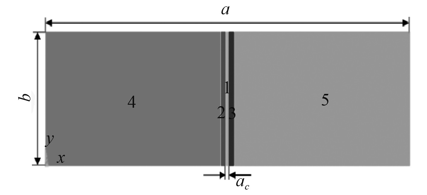
1 对接焊船体矩形板数值模拟 1.1 船体矩形板几何尺寸及材料属性计算模型几何尺寸选用ISSC所给出的船体板尺寸,具体为2 550 mm×850 mm×9.5 mm,几何模型如图1所示。图中,a为板长,b为板宽,ac为焊缝宽度。将图中几何模型以焊缝为基准划分为焊缝区1、过渡区(2和3)及远离焊缝区(4和5)。材料采用EH36高强度钢[22],材料属性包括热传导系数、比热容、弹性模量、热膨胀系数、屈服应力等,各参数随温度变化情况如图2所示。
|
图 1 对接焊矩形板几何模型 Fig. 1 Geometric model of butt welding rectangular plate |
1.2 单元属性、网格尺寸与边界条件
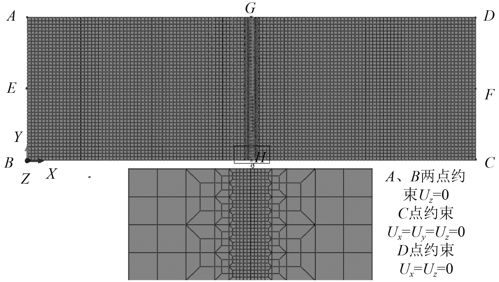
在热弹塑性有限元分析中,分别采用壳单元与实体单元离散对接焊船体矩形板获得有限元模型。壳单元模型截面属性厚度为2.375 mm,沿板厚方向有5个截面点,与实体单元模型节点位置相对应。表1为2种模型在不同分析中的单元类型及网格尺寸。为了兼顾计算精度与效率,焊缝附近区域有限元网格划分较为密集,远离焊缝区域的网格相对稀疏。为避免模型发生刚体位移,且允许结构在焊接过程中自由收缩,在有限元模型4个角点(A、B、C、D)处施加位移约束。热弹塑性有限元模型如图3所示。
|
|
表 1 单元类型与网格尺寸 Tab.1 Element type and mesh size |
|
图 3 热弹塑性有限元模型 Fig. 3 Thermal-elastic-plastic finite element models |
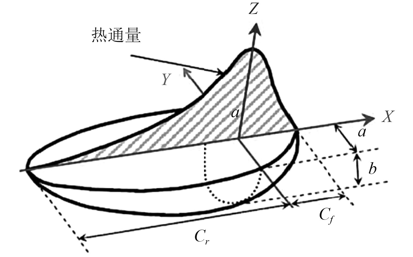
采用双椭球移动热源子程序进行焊接数值模拟,双椭球热源将总的热能输入分配前半椭球部分和后半椭球部分如图4所示[23]。
前半部分椭球内热源分布函数:
| ${{{q}}_1}(x,y,z) =\displaystyle \frac{{6\sqrt 3 {{{f}}_1}\eta UI}}{{{C_f}{{ab}}\text{π} \sqrt {\text{π}} }} \cdot \exp \left( { - \displaystyle\frac{{3{x^2}}}{{{C_f}^2}} - \displaystyle \frac{{3{y^2}}}{{{a^2}}} -\displaystyle \frac{{3{z^2}}}{{{b^2}}}} \right),$ | (1) |
后半部分椭球内热源分布函数:
| ${{{q}}_2}(x,y,z) =\displaystyle \frac{{6\sqrt 3 {{{f}}_2}\eta UI}}{{{C_r}{{ab}}\text{π} \sqrt {\text{π}} }} \cdot \exp \left( { - \displaystyle \frac{{3{x^2}}}{{{C_r}^2}} -\displaystyle \frac{{3{y^2}}}{{{a^2}}} -\displaystyle \frac{{3{z^2}}}{{{b^2}}}} \right)。$ | (2) |
式中:q1(x, y, z)和q2(x, y, z)分别为前半椭球和后半椭球所在空间内的任意位置的热流密度;a1为热源前端椭球半轴;a2为热源后端椭球半轴;b、c分别为沿厚度方向的半轴即垂直于焊缝方向的半轴;f1、f2分别为前半部分和后半部分的分配系数,应满足f1+f2=2;η为焊枪热输入效率;U为焊接电压;I为焊接电流;
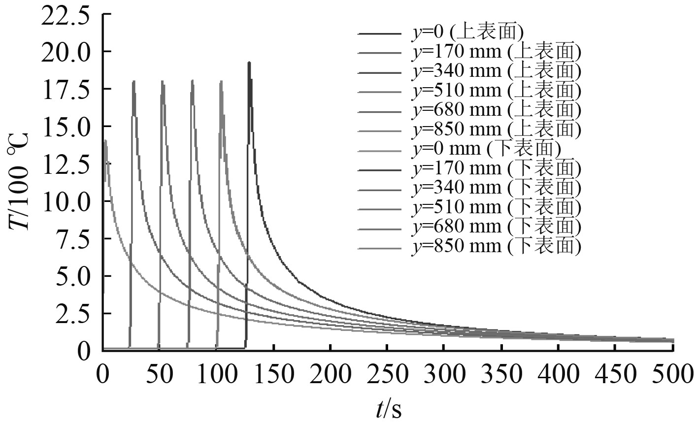
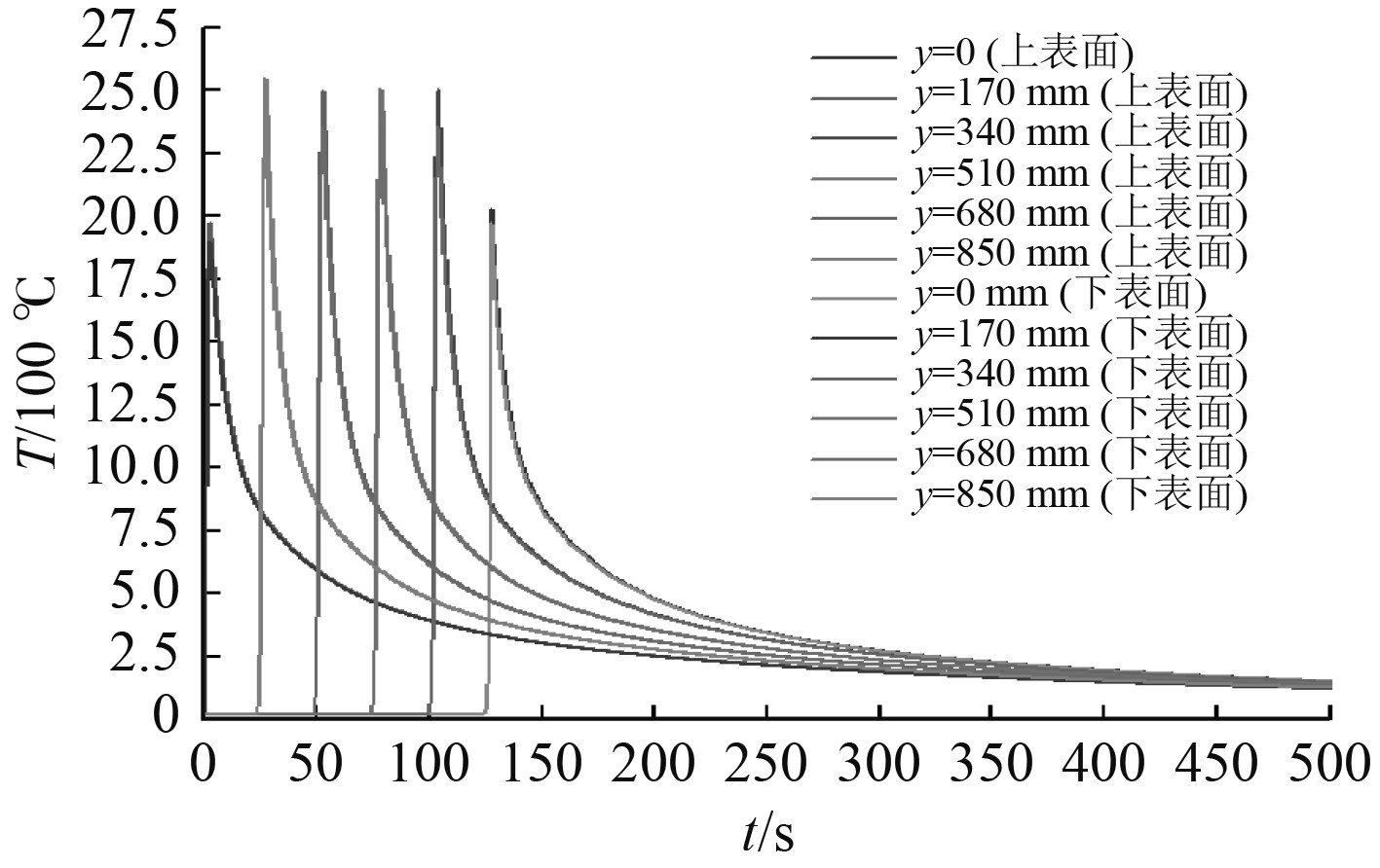
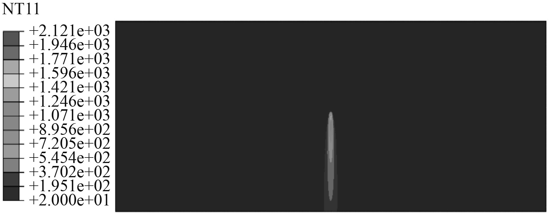
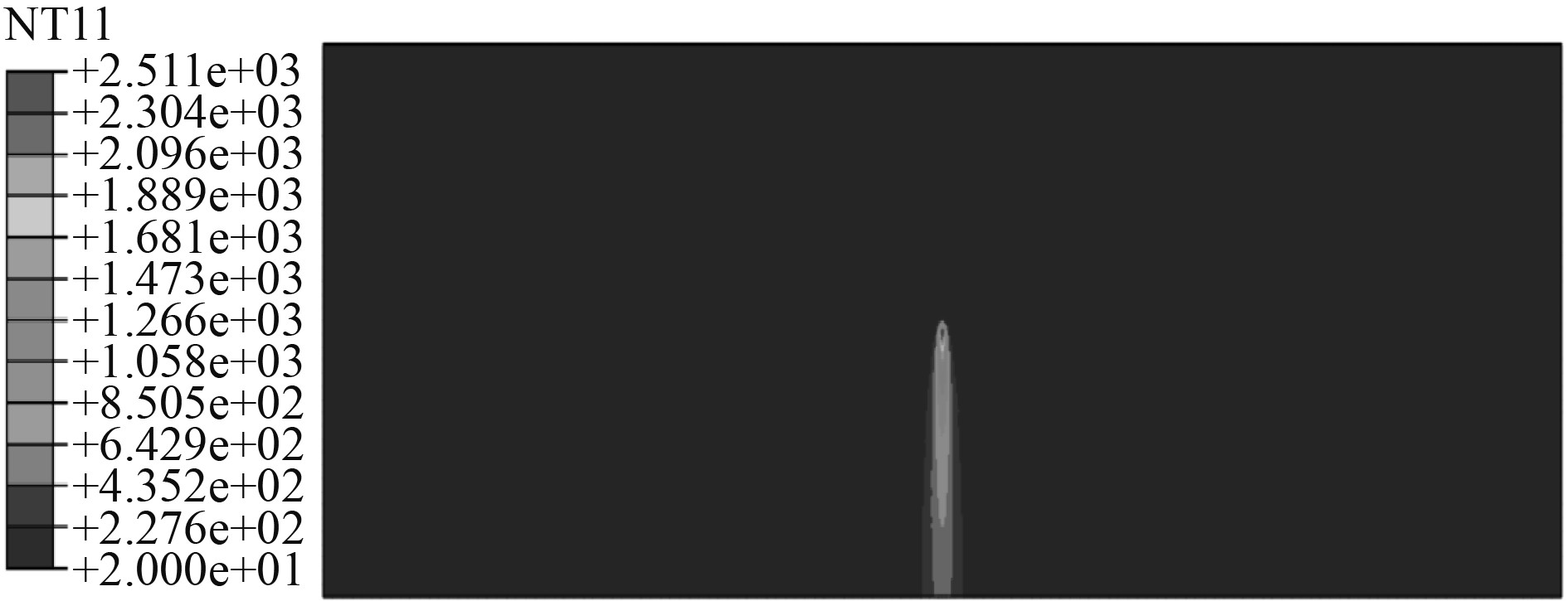
采用热弹塑性有限元法,分别对壳单元、实体单元模型开展焊接过程数值模拟。提取了焊接温度、纵向焊接残余应力与垂向挠度信息。图5和图6分别为壳单元、实体单元模型的焊缝上、下表面的温度历程。图7和图8分别为2种模型在稳态阶段时的温度分布图。可以发现,焊缝处2个模型各层的温度分布基本一致,壳、实体单元模型的最高温度均超过材料熔点1500 ℃。
|
图 5 壳单元模型热循环曲线 Fig. 5 Thermal cycle curves of shell element model |
|
图 6 实体单元模型热循环曲线 Fig. 6 Thermal cycle curves of solid element model |
|
图 7 壳单元模型准稳态温度场 Fig. 7 Quasi-steady state temperature field of shell element model |
|
图 8 实体单元模型准稳态温度场 Fig. 8 Quasi-steady state temperature field of solid element model |
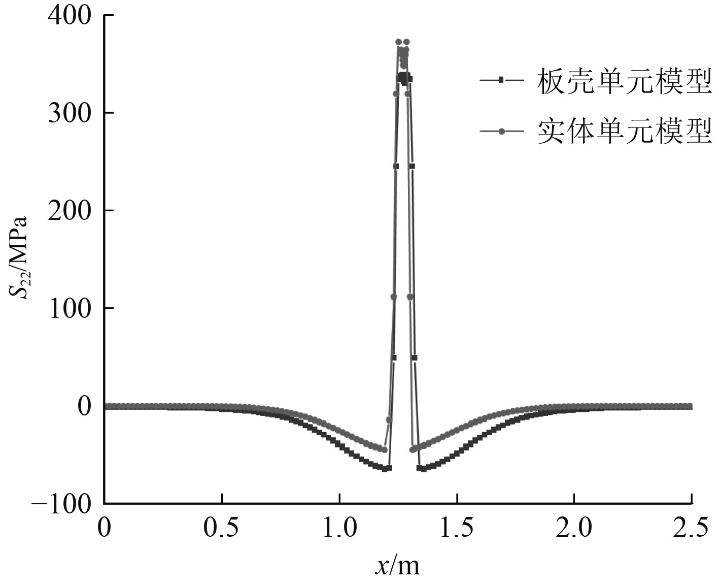
横向焊接残余应力对纵向受压矩形板极限强度影响较小,本文主要关注矩形板的纵向焊接残余应力。图9为壳单元模型的纵向焊接残余应力云图,图10为壳、实体单元模型沿中线E-F路径上的纵向焊接残余应力对比,表明2种模型焊后纵向焊接残余应力一致。

|
图 9 壳单元模型纵向焊接残余应力云图 Fig. 9 Longitudinal residual stress cloud diagram of shell element model |
|
图 10 对接焊矩形板纵向焊接残余应力分布(E-F) Fig. 10 Longitudinal residual stress distribution of butt welded rectangular plate (E-F) |
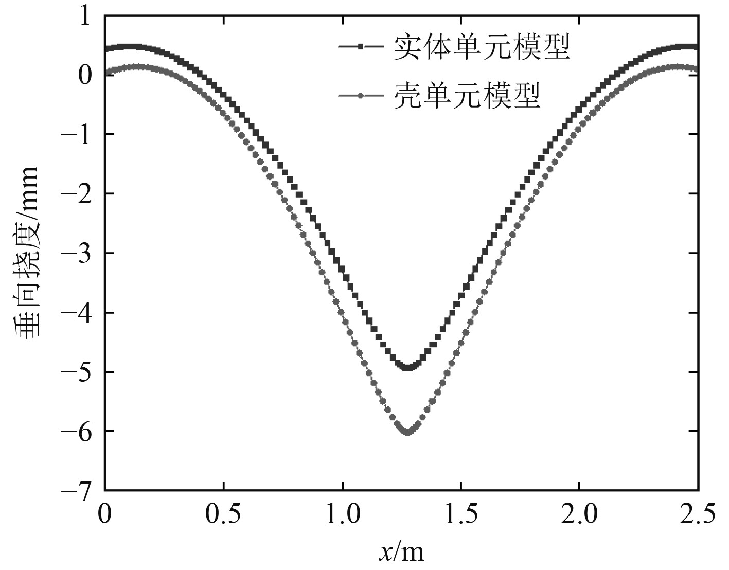
图11为壳、实体单元模型沿中线E-F路径垂向挠度,表明2种模型的垂向挠度变化规律一致,壳单元模型垂向挠度比实体单元模型大。
|
图 11 壳及实体单元模型垂向挠度 (E-F) Fig. 11 Vertical deflection of shell and solid element models (E-F) |
表2为同一软硬件环境下,壳、实体单元模型的单元与节点数与热分析与应力分析的计算时间。具体的计算机配置为:64位Windows操作系统,R7 4800H 处理器,CPU主频为2.90 GHz,内存为16 GB。从表3可知:壳单元模型能够有效地减少单元和节点数目,计算效率较实体单元模型显著提高。
|
|
表 3 2种模型单元与节点数、计算时间 Tab.3 The number of nodes and calculation time of the two models |
前文通过热弹塑性有限元法,获得了对接焊矩形板的焊接残余应力和变形,可作为极限强度非线性有限元数值模拟的初始缺陷。同时,矩形板材料属性选用EH36高强度钢在室温下的材料参数。为便于分析本文所采用计算路线的可行性,计算矩形板极限强度的有限元模型均采用壳单元模型,一并给出Faulkner简化公式计算结果。Faulkner简化为:
| $ \frac{{{\sigma _u}}}{{{\sigma _Y}}} = \frac{2}{\beta } - \frac{1}{{{\beta ^2}}}。$ | (3) |
式中:
本文采用2块不同厚度的矩形板作为极限强度分析模型,如图12所示。在极限强度分析中,矩形板两端部受纵向压缩荷载作用。矩形板极限强度分析模型几何尺寸及边界条件见表4。

|
图 12 极限强度非线性有限元模型 Fig. 12 Nonlinear finite element model of ultimate strength |
|
|
表 4 模型尺寸与边界条件 Tab.4 Model dimensions and boundary conditions |
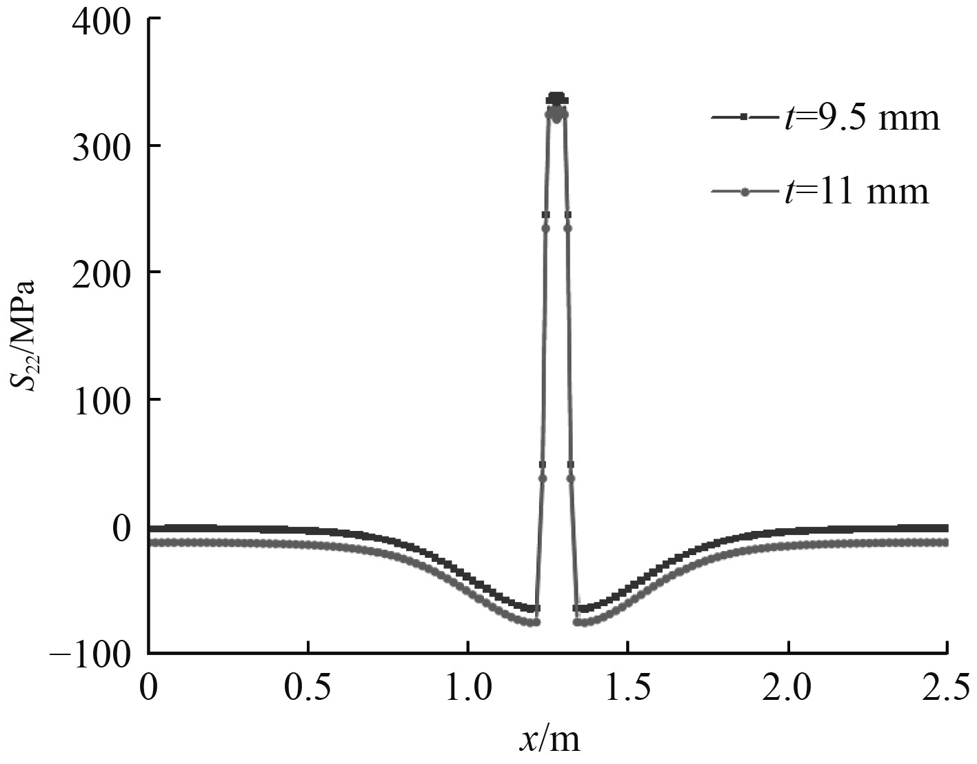
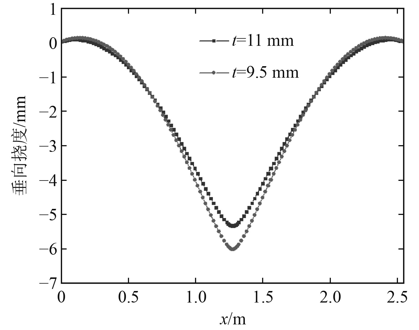
图13为初始状态时刻,厚度为9.5 mm和11 mm的对接焊矩形板沿中线E-F路径上的纵向焊接残余应力,对比发现2块矩形板的纵向焊接残余应力变化规律一致。图14为初始状态时刻,厚度为9.5 mm和11 mm的矩形板沿中线E-F路径垂向挠度,由图可知,2种厚度矩形板的垂向挠度变化规律一致,板厚为9.5 mm的矩形板垂向挠度峰值较大。
|
图 13 对接焊矩形板纵向焊接残余应力分布(E-F) Fig. 13 Longitudinal residual stress distribution of butt welded rectangular plate (E-F) |
|
图 14 壳单元模型垂向挠度 (E-F) Fig. 14 Vertical deflection of shell element models (E-F) |
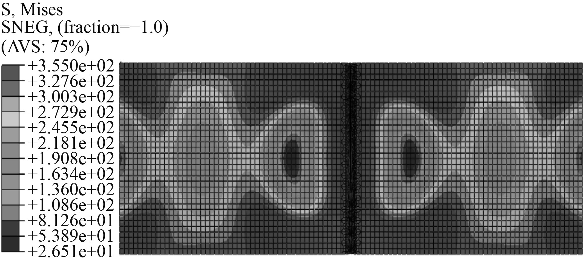
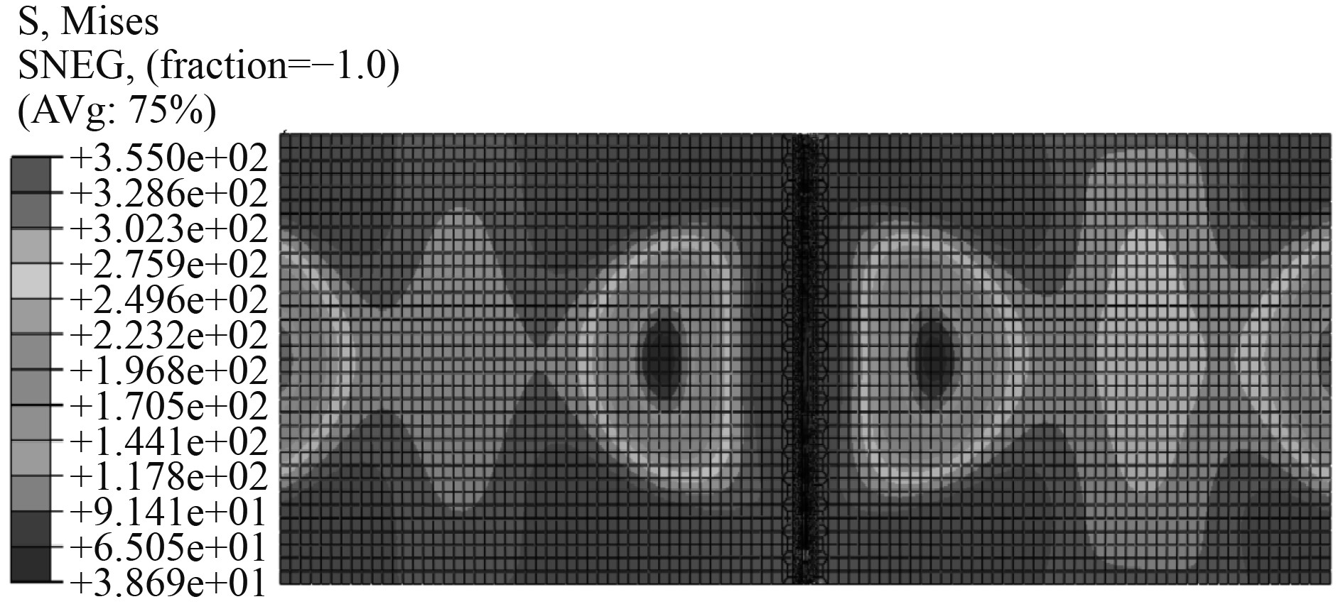
图15和图16分别为厚度为9.5 mm和11 mm的矩形板极限状态Von-Mises应力云图,可知:Von-Mises应力沿焊缝对称分布,在焊缝及其热影响区附近,其Von-Mises最大应力值接近钢材屈服强度。
|
图 15 9.5 mm矩形板极限状态Von-Mises应力云图 Fig. 15 Von-Mises stress cloud diagram of rectangular plate at ultimate state (t=9.5 mm) |
|
图 16 11 mm矩形板极限状态Von-Mises应力云图 Fig. 16 Von-Mises stress cloud diagram of rectangular plate at ultimate state (t=11 mm) |
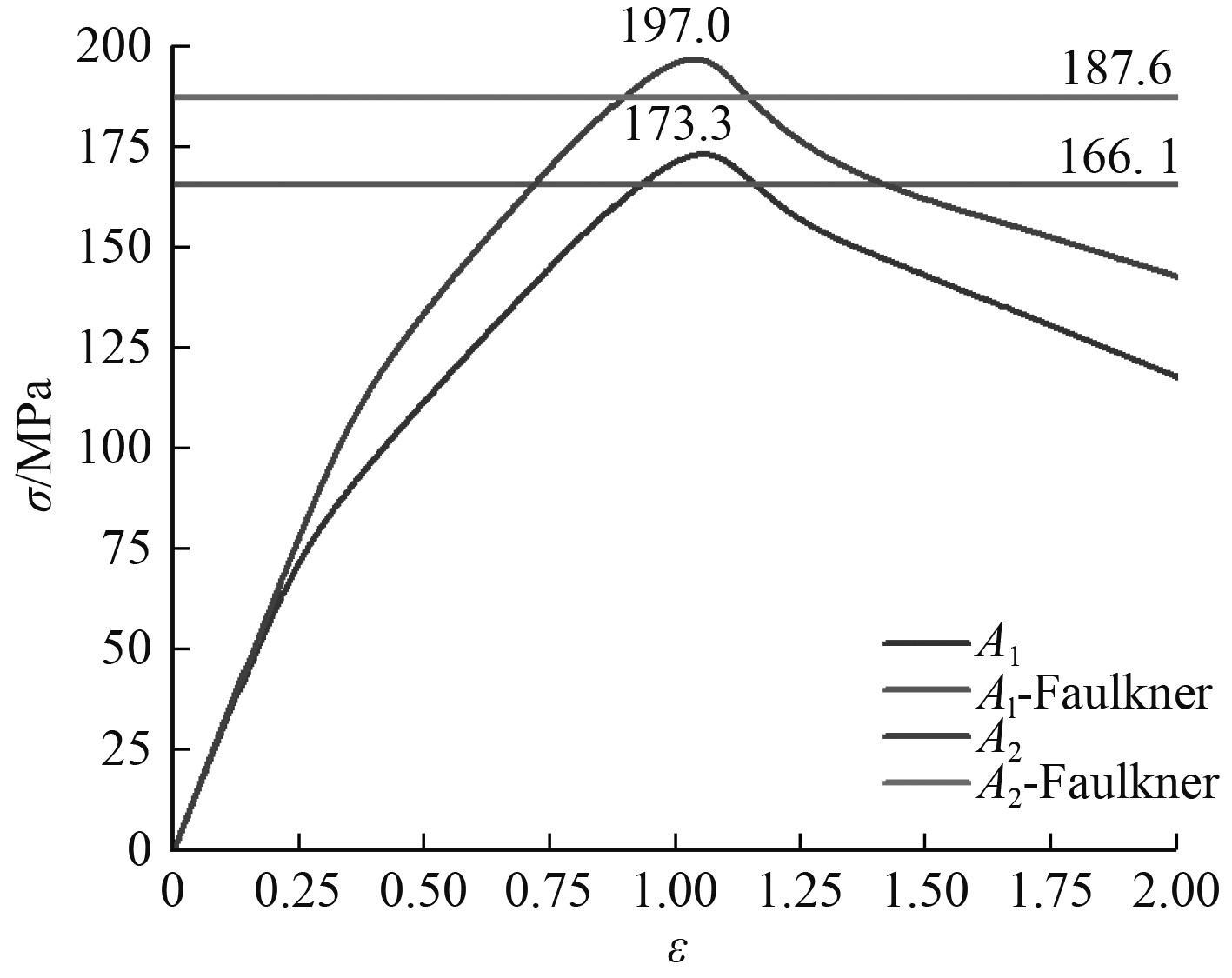
图17为厚度为9.5 mm、11 mm的对接焊矩形板应力-应变曲线,曲线中的峰值点所对应的应力即为矩形板的极限强度。可知:板厚为9.5 mm矩形板A1的最大峰值点对应的应力值为173.3 MPa, Faulkner公式计算的极限强度值为166.1 MPa;板厚为11 mm矩形板B1的最大峰值点对应的应力值为197.0 MPa,Faulkner公式计算的极限强度值为187.6 MPa。
|
图 17 矩形板应力-应变曲线 Fig. 17 Stress-strain curve of rectangular plates |
本文首先对对接焊船体矩形板进行热弹塑性有限元分析,对比了相同几何尺寸的壳、实体单元模型的温度场、应力场、变形等结果,并对比了2种模型的计算效率。继而对带有焊接残余应力与变形的壳单元模型,开展了压缩载荷下的极限强度非线性有限元数值模拟。最后,分别比较了2块不同厚度对接焊矩形板初始时刻纵向残余应力和垂向挠度分布规律、极限强度数值模拟结果与Faulkner公式计算结果,得到以下结论:
1)在保证一定计算精度的前提条件下,在热弹塑性有限元数值模拟中采用壳单元模型的计算效率较实体单元模型有显著提高。
2)在同一焊接工艺参数情况下,板厚对纵向焊接残余应力分布影响较小。但厚度为9.5 mm的矩形板垂向挠度峰值比厚度为11 mm的矩形板的垂向挠度峰值大。
3)不同厚度矩形板通过数值模拟得到的极限强度值,与Faulkner简化公式计算的极限强度值误差分别为4.2%和5.1%,因此数值模拟值与公式计算值较吻合。
4)基于热弹塑性有限元法,获得的焊接残余应力和变形,可作为对接焊矩形板极限强度非线性有限元数值模拟的初始缺陷。
| [1] |
UEDA Y, FUKUDA K, FUKUDA M. Measuring theory of three dimensional residual stresses in long welded joints. ly method and lz method[J]. Transactions of JWRI (Japanese Welding Research Institute), 1983, 12(1): 113-122. |
| [2] |
PAIK J K, PEDERSENN P T. Simplified method for predicting ultimate compressive strength of ship panels[J]. International Shipbuilding Progress, 1996, 43(434): 139-157. |
| [3] |
CUI W C, WANG D Y. Effects of welding distortions and residual stresses on the ultimate strength of long rectangular plates under uniaxial compression[J]. Marine Structures, 1998, 11(6): 251-269. DOI:10.1016/S0951-8339(98)00012-4 |
| [4] |
HU Y R, SUN J L. An approximate method to generate average stress-strain curve with the effect of residual stresses for rectangular plates under uniaxial compression in ship structures[J]. Marine Structures, 1999, 12(9-10): 585-603. DOI:10.1016/S0951-8339(00)00002-2 |
| [5] |
UEDA Y, YAO T. The influence of complex initial deflection modes on the behaviour and ultimate strength of rectangular plates in compression[J]. Journal of Constructional Steel Research, 1985, 5(4): 265-302. DOI:10.1016/0143-974X(85)90024-0 |
| [6] |
SOARES C G, GORDO J M. Compressive strength of rectangular plates. under biaxial load and lateral pressure[J]. Thin-Walled Structures, 1996, 24(3): 231-259. DOI:10.1016/0263-8231(95)00030-5 |
| [7] |
PAIK J K, THAYAMBALLI A K, KIM B J. Ultimate strength and effective width formulations for ship plating subject to combined axial load, edge shear, and lateral pressure[J]. Journal of Ship Research, 2000, 44(3): 247-258. |
| [8] |
SADOVSK Z, TEIXEIRA A P, SOARES C G. Degradation of the compressive strength of rectangular plates due to initial deflection[J]. Thin-Walled Structures, 2005, 43(1): 65-82. DOI:10.1016/j.tws.2004.08.005 |
| [9] |
PAIK J K, SOHN J M. Effects of welding residual stresses on high tensile steel plate ultimate strength: nonlinear finite element method investigations[J]. Journal of Offshore Mechanics & Arctic Engineering, 2012, 134(2): 021401. |
| [10] |
冯亮, 何京可, 史宏达, 等. 船体板格极限强度数值计算影响因素及敏感分析[J]. 舰船科学技术, 2017, 39(21): 48-53. FENG Liang, HE Jingke, SHI Hongda, et al. Influence factors and sensitivity analysis of numerical calculation of hull panel ultimate strength[J]. Ship Science and Technology, 2017, 39(21): 48-53. DOI:10.3404/j.issn.1672-7649.2017.11.010 |
| [11] |
YAO T, FUJIKUBO M. Buckling and ultimate strength of ship and ship-like floating structures [M]. Butterworth-Heinemann, 2016.
|
| [12] |
汪建华, 钟小敏, 上田幸雄, 等. 焊接结构三维热变形的有限元模拟[J]. 上海交通大学学报, 1994, 28(6): 59-65. |
| [13] |
MOLLICONE P, CAMILLERI D, GRAY T. Procedural influences on non-linear distortions in welded thin-plate fabrication[J]. Thin-Walled Structures, 2008, 46(7−9): 1021-1034. DOI:10.1016/j.tws.2008.01.044 |
| [14] |
RANJBAMODEH E, SERAJZADEH S, KOKABI A H, et al. Finite element modeling of the effect of heat input on residual stresses in dissimilar joints[J]. International Journal of Advanced Manufacturing Technology, 2011, 55(5-8): 649-656. DOI:10.1007/s00170-010-3095-3 |
| [15] |
OKANO S, TANAKA M, MOCHIZUKI M. Arc physics based heat source modelling for numerical simulation of weld residual stress and distortion[J]. Science & Technology of Welding & Joining, 2013, 16(3): 209-214. |
| [16] |
SINGH S, YADAIAH N, BAG S, et al. Numerical simulation of welding-induced residual stress in fusion welding process using adaptive volumetric heat source[J]. Proceedings of The Institution of Mechanical Engineers, Part C: Journal of Mechanical Engineering Science, 2014, 228(16): 2960-2972.
|
| [17] |
ATTARHA M J, SATTARI F. Study on welding temperature distribution in thin welded plates through experimental measurements and finite element simulation[J]. Journal of Materials Processing Technology, 2011, 211(4): 688-694. DOI:10.1016/j.jmatprotec.2010.12.003 |
| [18] |
SUN J, LIU X, TONG Y, et al. A comparative study on welding temperature fields, residual stress distributions and deformations induced by laser beam welding and co2 gas arc welding[J]. Materials & Design, 2014, 63: 519-530. |
| [19] |
CHOOBI M S, HAGHPANAHI M, SEDIGHI M. Investigation of the effect of clamping on residual stresses and distortions in butt-welded plates[J]. Scientia Iranica, 2010, 17(5): 387-394. |
| [20] |
CHEN B Q, SOARES C G. Numerical investigation on weld induced imperfections in aluminium ship plates[J]. Journal of Offshore Mechanics and Arctic Engineering, 2019, 141(6): 1-7. |
| [21] |
崔虎威, 樊开敬. 平板对接焊温度场与残余应力数值模拟[J]. 重庆交通大学学报(自然科学版), 2022, 41(9): 140-146. CUI Huwei, FAN Kaijing. Numerical simulation of temperature field and residual stress in flat plate butt welding[J]. Journal of Chongqing Jiaotong University (Natureal Science), 2022, 41(9): 140-146. |
| [22] |
倪连超, 陈震, 陶国君. EH36钢薄板对接焊接变形数值模拟[J]. 焊接, 2014(2): 56-62+72. NI Lianchao, CHEN Zhen, TAO Guojun. Numerical simulation of deformation of EH36 steel sheet butt welding[J]. Welding, 2014(2): 56-62+72. |
| [23] |
GOLDAK J, CHAKRAVARTI A, BIBBY M. A new finite element model for welding heat sources[J]. Metallurgical And Materials Transactions B-process Metallurgy And Materials Processing Science, 1984, 15(2): 299-305. |
| [24] |
陈冰泉. 船舶及海洋工程结构焊接[M]. 北京: 人民交通出版社, 2001.
|
 2024, Vol. 46


