多相永磁同步电机由于转矩脉动小,容错能力强,可使用低功率等级器件实现低压大功率调速等优点,被广泛应用于船舶电力推进系统 [1 − 2]。双Y移30°永磁同步电机(Dual Three- Phase Permanent Magnet Synchronous Motor,DTP-PMSM)作为船舶电力推进电机,在控制时需实时的转子位置信息,当机械的位置传感器系统在极端工况下出现故障时,无位置传感器控制可提高系统的容错能力,进一步增加设备的可靠性[3 − 4]。
目前永磁同步电机的无位置传感器方法主要分为两类。一类是基于电机基波激励模型中与转速有关的量进行转子位置和速度估算,常见的有滑膜观测器[5],扩展卡尔曼滤波[6],模型参考自适应[7]等。但电机在低速运行时,信噪比很低,有用的信息很难获取,因此此类算法更适用于电机中高速运行阶段。
另外一类是向电机注入高频信号,利用电机的凸极特性进行转子位置估算,此类方法不依赖电机基波模型,可实现电机在零低速阶段的无位置传感器控制[8 − 10]。刘颖等[11]提出了一种基于高频电流注入的无位置传感器控制方法,在估计同步旋转坐标系直轴上注入高频电流,然后检测交轴电流环PI输出的电压来估计转子位置。但PI控制难以跟踪高频电流,进而影响转子位置的估算。在高频电压注入的方法中,张烨璐等[12]采用低速高频注入和高速滑膜观测器结合的复合算法进行DTP-PMSM全速范围内的无位置传感器控制,在低速时采用的旋转高频电压注入法主要依赖于电机转子的凸极性,对于表贴式电机并不适用。徐斌等[13]采用了高频脉振电压注入法,高频电压信号从
针对上述问题,本文提出一种基于高频方波注入法的DTP-PMSM低速无传感器控制策略,将信号注入周期和磁场定向控制(Field Oriented Controller,FOC)周期进行分离,在高频注入周期给同步旋转坐标系的
基于矢量空间解耦(Vector Space Decomposition,VSD)坐标变换,将双三相永磁同步电机的六维空间向量经过坐标变换映射到3个相互正交的子平面,
DTP-PMSM在同步旋转坐标
| $ \left\{ \begin{gathered} {u_d} = R{i_d} + {L_d}\frac{{\mathrm{d}}}{{{{\mathrm{d}}t}}}{i_d} - {\omega _e}{L_q}{i_q},\\ {u_q} = R{i_q} + {L_q}\frac{{\mathrm{d}}}{{{{\mathrm{d}}t}}}{i_q} + {\omega _e}{L_d}{i_d} + {\omega _e}{\psi _f} 。\end{gathered} \right. $ | (1) |
式中:
当电机在零低速运行时,与转子角速度
| $ \left[ \begin{gathered} {u_{dh}} \\ {u_{qh}} \\ \end{gathered} \right]{\text{ = }}\left[ {\begin{array}{*{20}{c}} {{L_{dh}}}&0 \\ 0&{{L_{qh}}} \end{array}} \right]\frac{{\mathrm{d}}}{{{\mathrm{d}}t}}\left[ \begin{gathered} {i_{dh}} \\ {i_{qh}} \\ \end{gathered} \right]。$ | (2) |
式中:
图1为表贴式DTP-PMSM基于传统脉振高频电压注入法的无位置传感器控制框图,向同步旋转坐标系的d轴注入高频电压信号,因为电感的非线性饱和,电机会呈现饱和凸极性,从估计同步旋转轴系提取高频响应电流进行处理,获得转子位置估算值,简单分析其实现过程。
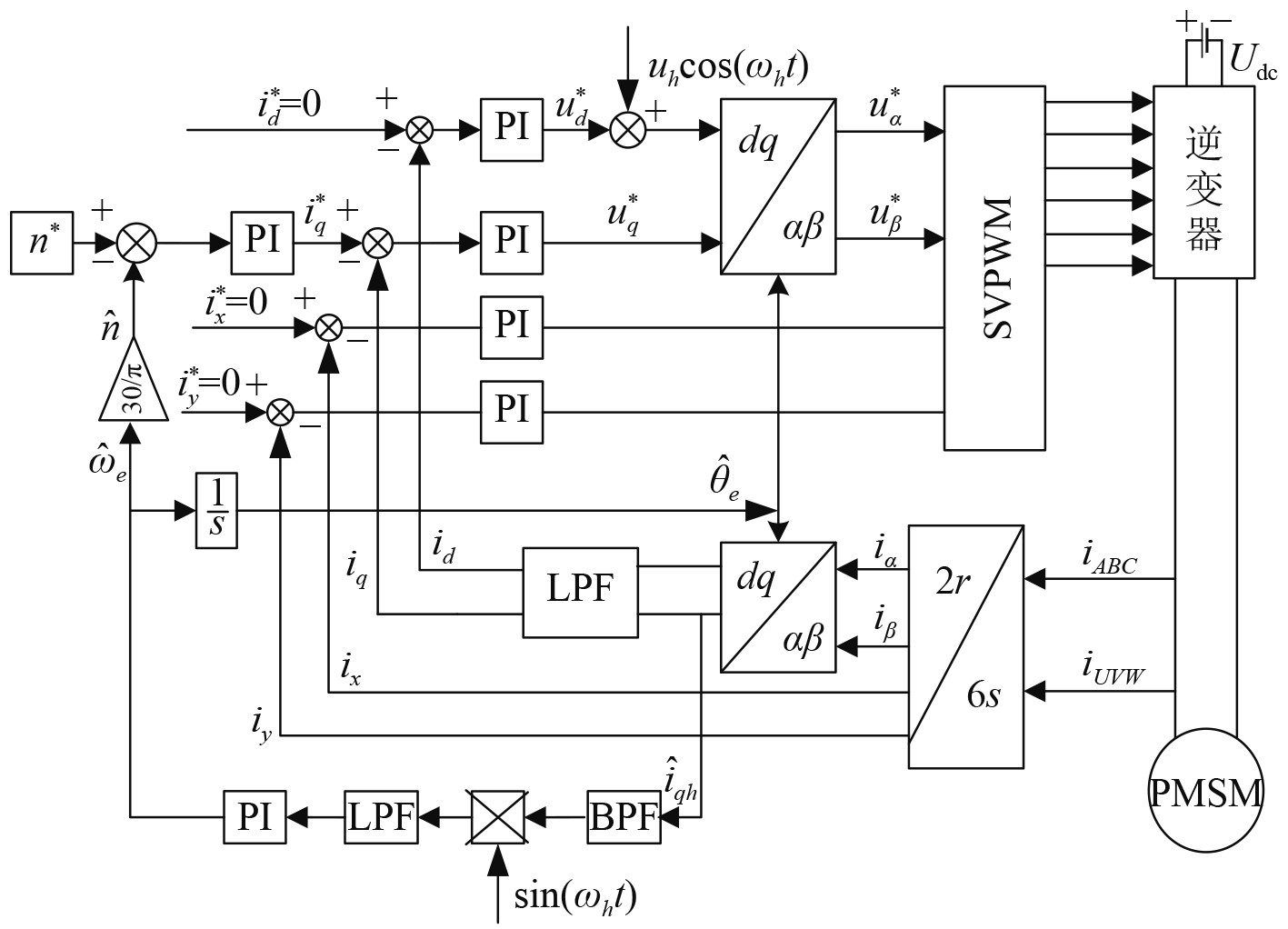
|
图 1 DTP-PMSM传统脉振高频信号注入系统框图 Fig. 1 Block diagram of DTP-PMSM based on traditional pulsating high frequency signal injection |
两相静止坐标系

|
图 2 坐标转换关系图 Fig. 2 Diagram of coordinate frames |
图中,
| $ \frac{{\mathrm{d}}}{{{\mathrm{d}}t}}\left[ \begin{gathered} {{\hat i}_{dh}} \\ {{\hat i}_{qh}} \\ \end{gathered} \right] = {T^{ - 1}}\left( {{{\tilde \theta }_e}} \right)\frac{{\mathrm{d}}}{{{\mathrm{d}}t}}\left[ \begin{gathered} {i_{dh}} \\ {i_{qh}} \\ \end{gathered} \right],$ | (3) |
| $ \left[ \begin{gathered} {{\hat u}_{dh}} \\ {{\hat u}_{qh}} \\ \end{gathered} \right] = {T^{ - 1}}\left( {{{\tilde \theta }_e}} \right)\left[ \begin{gathered} {u_{dh}} \\ {u_{qh}} \\ \end{gathered} \right] $ | (4) |
式中:
由式(2)~式(4)可得估计同步旋转坐标系
| $ \frac{{\mathrm{d}}}{{{\mathrm{d}}t}}\left[ \begin{gathered} {{\hat i}_{dh}} \\ {{\hat i}_{qh}} \\ \end{gathered} \right] = {T^{ - 1}}\left( {{{\tilde \theta }_e}} \right)\left[ {\begin{array}{*{20}{c}} {\frac{1}{{{L_{dh}}}}}&0 \\ 0&{\frac{1}{{{L_{qh}}}}} \end{array}} \right]T\left( {{{\tilde \theta }_e}} \right)\left[ \begin{gathered} {{\hat u}_{dh}} \\ {{\hat u}_{qh}} \\ \end{gathered} \right]。$ | (5) |
估计同步旋转坐标系的
| $ \left\{ \begin{gathered} {{\hat u}_{dh}} = {u_h}\cos {\omega _h}t ,\\ {{\hat u}_{qh}} = 0。\end{gathered} \right. $ | (6) |
式中:
| $ \left[ \begin{gathered} {{\hat i}_{dh}} \\ {{\hat i}_{qh}} \\ \end{gathered} \right]{\text{ = }}\frac{{{u_h}\sin {\omega _h}t}}{{{\omega _h}\left( {{L^2} - \Delta {L^2}} \right)}}\left[ \begin{gathered} L + \Delta L\cos 2{{\tilde \theta }_e} \\ \Delta L\sin 2{{\tilde \theta }_e} \\ \end{gathered} \right] 。$ | (7) |
式中,
将
| $ \varepsilon = LPF\left( {{{\hat i}_{qh}}\sin {\omega _h}t} \right) = {k_\varepsilon }\sin 2{\tilde \theta _e}。$ | (8) |
式中,
本文提出基于高频方波电压注入的DTP-PMSM低速阶段无传感器控制算法,框图如图3所示。
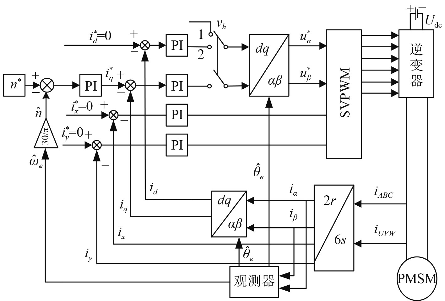
|
图 3 DTP-PMSM改进高频方波注入系统框图 Fig. 3 Block diagram of DTP-PMSM based on high frequency square wave injection |
如图4所示,当开关位置在1时,向
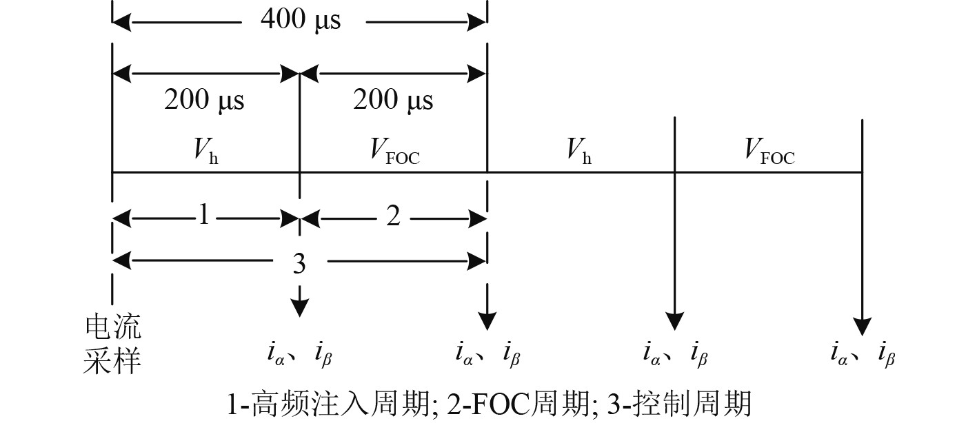
|
图 4 电压注入方式 Fig. 4 Implement of voltage injection scheme |
在高频注入周期前后对
在高频注入环节输入观测器的高频电流不含有基波分量,所以无需滤波器滤除即可估计转子位置,而电流环PI只在FOC周期开始点有电流响应,不会响应太高频率的信号,因此在位置估计和电流环节均无需使用数字滤波器。
根据图2可得,在
| $ \frac{{\mathrm{d}}}{{{\mathrm{d}}t}}\left[ \begin{gathered} {i_{\alpha h}} \\ {i_{\beta h}} \\ \end{gathered} \right] = {T^{ - 1}}\left( {{{\hat \theta }_e}} \right)\frac{{\mathrm{d}}}{{{\mathrm{d}}t}}\left[ \begin{gathered} {{\hat i}_{dh}} \\ {{\hat i}_{qh}} \\ \end{gathered} \right]。$ | (9) |
式中:
将式(5)代入式(9),可得:
| $ \frac{{\mathrm{d}}}{{{\mathrm{d}}t}}\left[ \begin{gathered} {i_{\alpha h}} \\ {i_{\beta h}} \\ \end{gathered} \right] = {T^{ - 1}}\left( {{{\hat \theta }_e}} \right){T^{ - 1}}\left( {{{\tilde \theta }_e}} \right)\left[ {\begin{array}{*{20}{c}} {\frac{1}{{{L_{dh}}}}}&0 \\ 0&{\frac{1}{{{L_{qh}}}}} \end{array}} \right]T\left( {{{\tilde \theta }_e}} \right)\left[ \begin{gathered} {{\hat u}_{dh}} \\ {{\hat u}_{qh}} \\ \end{gathered} \right]。$ | (10) |
对于表贴式永磁电机交直轴电感近似相等,即
| $ \left[ \begin{gathered} \Delta {i_{\alpha h}} \\ \Delta {i_{\beta h}} \\ \end{gathered} \right] = \frac{{\Delta t}}{{{L_s}}}\left[ {\begin{array}{*{20}{c}} {\cos {{\hat \theta }_e}}&{ - \sin {{\hat \theta }_e}} \\ {\sin {{\hat \theta }_e}}&{\cos {{\hat \theta }_e}} \end{array}} \right]\left[ \begin{gathered} {{\hat u}_{dh}} \\ {{\hat u}_{qh}} \\ \end{gathered} \right]。$ | (11) |
式中:
高频注入周期内的注入电压可表示为式(2),
| $ \left[ \begin{gathered} {{\hat u}_{dh}} \\ {{\hat u}_{qh}} \\ \end{gathered} \right] = \left[ \begin{gathered} {V_h} \\ {\text{0}} \\ \end{gathered} \right]。$ | (12) |
将式(12)代入式(11),可得高频注入后两相静止
| $ \left[ \begin{gathered} \Delta {i_{\alpha h}} \\ \Delta {i_{\beta h}} \\ \end{gathered} \right] = \frac{{{V_h}\Delta t}}{{{L_s}}}\left[ \begin{gathered} \cos {{\hat \theta }_e} \\ \sin {{\hat \theta }_e} \\ \end{gathered} \right]。$ | (13) |
当估计角度误差足够小,即
| $ \left[ \begin{gathered} \Delta {i_{\alpha h}} \\ \Delta {i_{\beta h}} \\ \end{gathered} \right] \approx \frac{{{V_h}\Delta t}}{{{L_s}}}\left[ \begin{gathered} \cos {\theta _e} \\ \sin {\theta _e} \\ \end{gathered} \right]。$ | (14) |
从式(13)可看出,
高频响应电流经过正交锁相环估算出转子位置角和转速,具体结构如图5所示。

|
图 5 正交锁相环结构图 Fig. 5 Block of the quadrature phase locked loop |
根据图5可得转子位置误差信号为:
| $ \varepsilon = \Delta {i_{\beta h}}\cos {\hat \theta _e} - \Delta {i_{\alpha h}}\sin {\hat \theta _e} = \frac{{{V_h}\Delta t}}{{{L_s}}}\sin \left( {{\theta _e} - {{\hat \theta }_e}} \right)。$ | (15) |
当实际角和估计角
| $ \varepsilon \approx \frac{{{V_h}\Delta t}}{{{L_s}}}\left( {{\theta _e} - {{\hat \theta }_e}} \right) = {k_\varepsilon }\left( {{\theta _e} - {{\hat \theta }_e}} \right) 。$ | (16) |
式中,
锁相环的闭环传递函数为:
| $ \frac{{{{\hat \theta }_e}}}{{{\theta _e}}} = \frac{{{k_\varepsilon }{k_p}s + {k_\varepsilon }{k_i}}}{{{s^2} + {k_\varepsilon }{k_p}s + {k_\varepsilon }{k_i}}}。$ | (17) |
可看出
基于Matlab/Simulink平台搭建DTP-PMSM无位置传感器控制系统模型,包括基于传统高频脉振电压注入和改进基于高频方波电压注入的模型。在低速阶段模拟船舶运行过程中常见的转速突变和负荷突变工况分别进行仿真,某船电机参数如表1所示。
|
|
表 1 双三相PMSM参数 Tab.1 DTP-PMSM parameters |
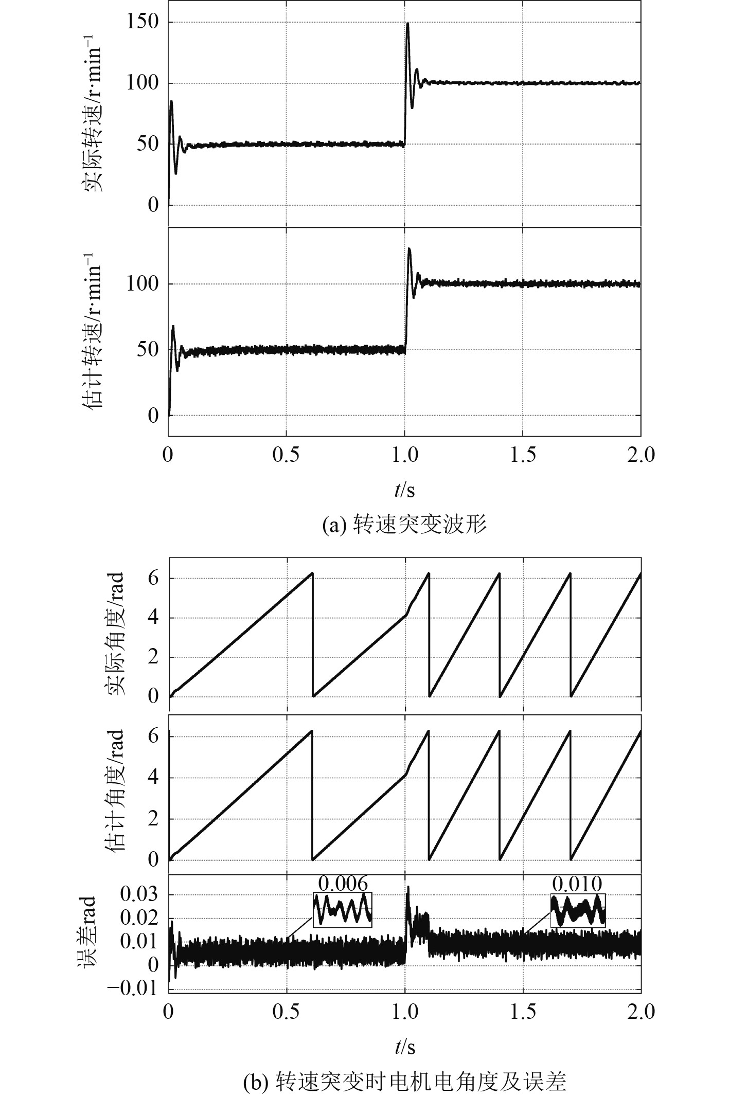
给定电机起动转速为50 r/min,在1.0 s时突加到100 r/min,负载恒定为100 N·m,图6(a)和图7(a)分别为基于传统高频注入和改进高频方波注入得到的电机转速突变下,实际转速和估计转速的对比波形。图6(b)和图7(b)分别为转速突变下电机转子的实际角度,估计角度和角度估计误差。
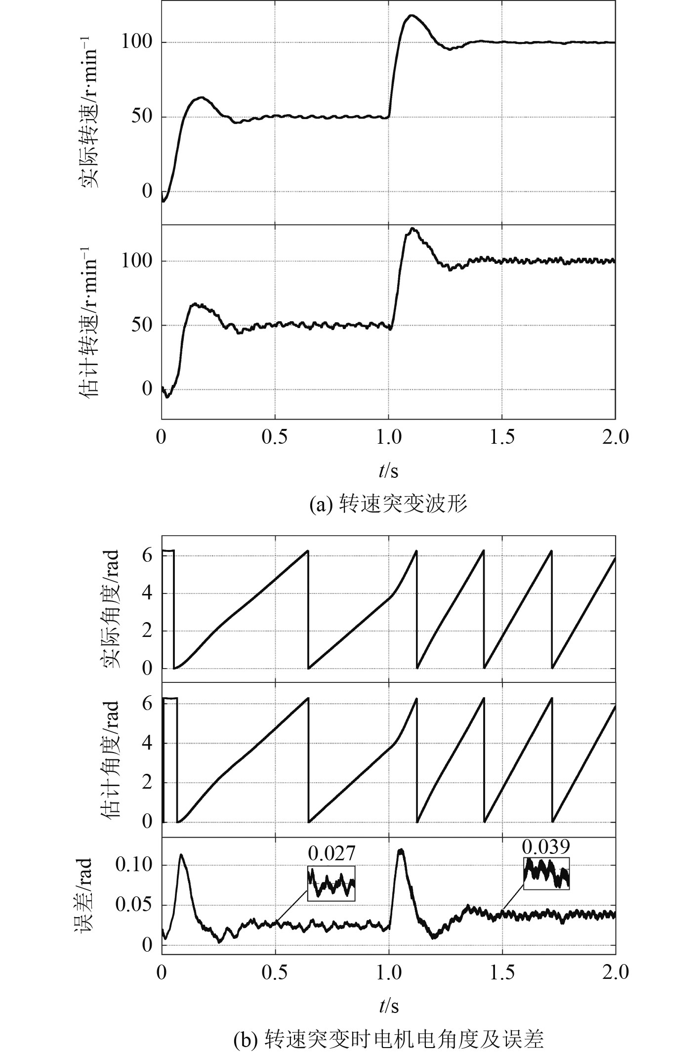
|
图 6 转速突变时传统高频脉振电压注入法动态性能 Fig. 6 Dynamic performance of traditional high frequency pulsating voltage injection with speed step |
|
图 7 转速突变时改进高频方波电压注入法动态性能 Fig. 7 Dynamic performance of improved high frequency square wave signal injection with speed step |
从图6可看出,转速突变时基于传统高频脉振电压注入的电机可有效估算转子位置和转速。与图7的转速和位置角波形对比可看出,传统方法存在一定的响应延迟,在转速突变后需约0.4 s才能重新追踪到转子位置并恢复稳定,而改进方法只需0.1 s;传统方法在50 r/min时,转子位置估计误差约为0.027 rad,100 r/min时误差约为0.039 rad,而改进方法在50 r/min时,角度估计误差为0.006 rad,100 r/min时为0.01 rad。可看出模型在低速阶段转速突变时改进高频方波注入法,在系统响应速度和角度估计精度上均好于传统高频脉振注入法。
4.2 负荷突变仿真设置电机转速恒定在50 r/min,给定初始负载转矩为100 N·m,0.5 s突加到300 N·m,1.5突减到200 N·m,图8(a)和图9(a)分别为基于传统高频注入和改进高频方波注入得到的电机电磁转矩波形,图8(b)和图9(b)为负载突变下转子位置角的实际值、估计值和估算误差。

|
图 8 负荷突变时传统高频脉振电压注入法动态性能 Fig. 8 Dynamic performance of traditional high frequency pulsating voltage injection with torque step |

|
图 9 负荷突变时改进高频方波电压注入法动态性能 Fig. 9 Dynamic performance of improved high frequency square wave signal injection with torque step |
从图8和图9可看出,当电机低速阶段负荷发生突变时,基于2种方法的模型都能够有效地估计转子位置信息,但相比较改进的高频方波注入法,基于传统高频脉振电压注入法控制的电机在负荷突变后会出现较大波动,负荷突增时电磁转矩超调量约为23%,而且需约0.4 s才恢复稳定,远大于改进方法约16%的超调量和0.1 s的响应时间。改进的高频方波电压注入法在负荷突变过程中,转子位置角误差基本稳定在0.01 rad,远小于传统高频注入的0.037 rad。
经过对比仿真分析可看出,针对表贴式DTP-PMSM低速无位置传感器控制,无论是转速突变还是负荷突变的工况下,改进高频方波电压注入法与传统高频脉振电压注入法相比,因为减少了滤波器的使用,能够以更快的响应速度来追踪转子实际位置,具有更好的动态性能和稳定精度。
5 结 语针对传统高频脉振电压注入法应用于表贴式双三相永磁同步电机时,存在凸极特性不明显和滤波器过多使用造成的滞后效应叠加、动态性能下降等问题。本文提出一种将高频方波注入周期和磁场定向控制周期分离的方法,直接从两相静止坐标轴
| [1] |
马伟明, 王东, 程思为, 等. 高性能电机系统的共性基础科学问题与技术发展前沿[J]. 中国电机工程学报, 2016, 36(8): 2025-2035. |
| [2] |
刘自程, 李永东, 郑泽东. 多相电机控制驱动技术研究综述[J]. 电工技术学报, 2017, 32(24): 17-29. |
| [3] |
李伟超, 孟永刚, 高大威. 双三相永磁同步电机控制算法仿真分析[J]. 汽车安全与节能学报, 2019, 10(3): 349-356. |
| [4] |
BIN Xu, LUO Xiang, ZHU Li, et al. Sensorless control of dual three-phase PMSM with high frequency voltage signal injection[C]//2019 22nd International Conference on Electrical Machines and Systems(ICEMS), IEEE, Harbin, 2019.
|
| [5] |
杨淑英, 刘世园, 李浩源, 等. 永磁同步电机无位置传感器控制谐波抑制策略研究[J]. 中国电机工程学报, 2019, 39(20): 6075-6084. |
| [6] |
MYNAR Z, VACLAVEK P, BLAHA P. Synchronous reluctance motor parameter and state estimation using extended kalman filter and current derivative measurement[J]. IEEE Transactions on Industrial Electronics, 2021, 68(3): 1972-1981. DOI:10.1109/TIE.2020.2973897 |
| [7] |
钟臻峰, 金孟加, 沈建新. 基于分段PI调节器的模型参考自适应永磁同步电动机全转速范围无传感器控制[J]. 中国电机工程学报, 2018, 38(4): 1203-1211. |
| [8] |
李洁, 周波, 刘兵, 等. 表贴式永磁同步电机无位置传感器起动新方法[J]. 中国电机工程学报, 2016, 36(9): 2513-2520. |
| [9] |
杜思宸, 全力, 朱孝勇, 等. 基于高频注入的永磁同步电机零低速下位置传感器失效故障容错控制[J]. 中国电机工程学报, 2019, 39(10): 3038-3046. |
| [10] |
NI Ronggang, XU Dianguo, BLAABJERG F, et al. Square-wave voltage injection algorithm for PMSM position sensorless control with high robustness to voltage errors[J]. IEEE Transactions on Power Electronics, 2017, 32(7): 5425-5437. DOI:10.1109/TPEL.2016.2606138 |
| [11] |
刘颖, 周波, 冯瑛, 等. 基于脉振高频电流注入SPMSM低速无位置传感器控制[J]. 电工技术学报, 2012, 27(7): 139-145. |
| [12] |
张烨璐, 杨欢, 王海兵, 等. 双三相PMSM全速范围内无位置传感器控制研究[J]. 微电机, 2018, 51(11): 31-39+44. |
| [13] |
徐斌, 罗响, 朱莉. 基于PR控制及高频信号注入的双三相永磁同步电机无位置传感器控制[J]. 微电机, 2020, 53(4): 33-38. |
| [14] |
周中坚, 张成宝. 基于双三相永磁同步电机的EPS系统低速段无位置传感器控制[J]. 电机与控制应用, 2019, 46(12): 99-104. |
| [15] |
YOON Y D, SUL S K. Sensorless control for induction machines based on square-wave voltage injection[J]. IEEE Transactions on Power Electronics, 2014, 29(7): 3637-3645. DOI:10.1109/TPEL.2013.2278103 |
 2024, Vol. 46
