随着直线感应电机(Linear Induction Motor, LIM)在轨道交通、电磁发射、直驱伺服等领域的应用,其运行效率低下的问题受到愈来愈多的关注[1]。当电机结构设计确定,最小损耗(效率优化)控制技术通常分为搜索法和模型法最小损耗控制(Loss Minimization Control, LMC)。后者由于高实时性、低推力(转矩)震荡的特点,受到更广泛的应用[2]。但模型法也存在局限性:模型法的精确性受到电机参数的影响[3],而且LIM存在动态边端效应导致的激磁电感下降和铁损电阻增加[4],为了提高损耗模型的准确性,需要以提升模型的计算复杂度为代价。对于旋转感应电机(Rotary Induction Motor, RIM)的最小损耗控制早已存在大量研究[5],但LIM独有的大气隙、半填充槽、边端效应等结构、电磁特性,使得LIM不能直接套用现有的RIM的控制策略[6]。
为了用模型法对LIM进行最小损耗控制,需要建立有别于RIM的损耗模型,在建立模型的过程中需要对模型的准确性和计算复杂度进行折中考虑。早期研究中,为了简化模型,采取直接使用RIM模型[7]或者忽略漏感的方式[8],但是结果误差较大。Kim等[9]提出了4个修正系数Kx、Kr、Cx、Cr,分别描述纵向边端效应和横向边缘效应的电机模型,并且引入大量电机设计参数,由此推导了相应的电机损耗模型,在此基础上还将逆变器损耗加入模型,建立了驱动系统级别的最小损耗控制策略,但由于引入众多参数,模型的计算复杂度显著提高,最优磁链需要使用牛顿迭代法进行多次迭代求解,这会极大增加微控制器的运算负荷。Dong等[10]考虑动态边端效应的影响,仅引入2个修正系数对多级LIM建立了数学模型,此外激磁电感上并联的电阻改进为串联边端效应损耗电阻,显著减小了损耗模型的计算复杂度。
本文在Han等[11]提出的LIM数学模型的基础上,综合考虑动态边端效应和漏感影响,推导出一种计算复杂度适中新损耗模型,进而得出一种准确而易行的新型LMC策略。通过和传统的磁场定向控制(Field-Oriented Control, FOC)在轻载工况下进行仿真对比,验证了提出策略的可行性和优越性。
1 LIM的不对称等效电路模型 1.1 LIM等效变换选用的LIM等效电路的原型为2套绕组对应相间互差30°的双三相感应电机,2套绕组中性点星形连接且互相隔离。为了简化分析,采用广义的Clarke变换进行空间矢量解耦[12]得到仅涉及机电能量转换的α-β子平面数学模型,再通过Park变换进行矢量解耦得到d-q轴系的等效电路和数学模型。功率不变原则下,广义Clarke变换矩阵和Park变换矩阵分别为:
| $ T_{\text{up}}=\dfrac{\sqrt{3}}{3}\left[\begin{array}{*{20}{c}} 1 & -\dfrac{1}{2} & -\dfrac{1}{2} & \dfrac{\sqrt{3}}{2} & -\dfrac{\sqrt{3}}{2} & 0 \\ 0 & \dfrac{\sqrt{3}}{2} & -\dfrac{\sqrt{3}}{2} & -\dfrac{1}{2} & \dfrac{1}{2} & -1 \\ 1 & -\dfrac{1}{2} & -\dfrac{1}{2} & -\dfrac{\sqrt{3}}{2} & \dfrac{\sqrt{3}}{2} & 0 \\ 0 & -\dfrac{\sqrt{3}}{2} & \dfrac{\sqrt{3}}{2} & \dfrac{1}{2} & \dfrac{1}{2} & -1 \\ 1 & 1 & 1 & 0 & 0 & 0 \\ 0 & 0 & 0 & 1 & 1 & 1 \end{array}\right] ,$ | (1) |
| $ T_{d-q}=\left[\begin{array}{ccc} \cos \theta & \sin \theta & 0 \\ -\sin \theta & \cos \theta & 0 \\ 0 & 0 & {\boldsymbol{I}}_{4} \end{array}\right] 。$ | (2) |
式中,I4为四阶单位矩阵。经过式(1)变换,双三相LIM模型等效为自然坐标系下的三相LIM模型。
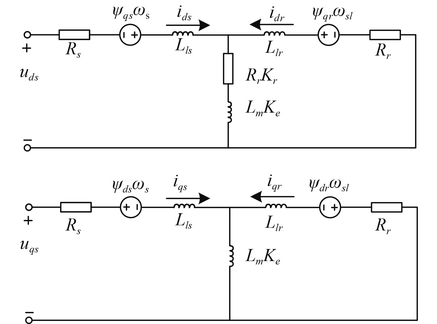
1.2 LIM数学模型经过坐标变换,可以建立考虑动态边端效应的同步旋转d-q轴系下LIM不对称等效电路如图1所示。该d-q轴等效电路由T型单相等效电路推导而得,与常规的RIM d-q轴等效电路形式一致,因而其复杂度没有明显增大。

|
图 1 LIM的d-q轴系不对称等效电路 Fig. 1 Asymmetric equivalent circuit of LIM in d-q coordinate frame |
图中磁链、电感和电阻分别用Ψ、L、R表示,各物理量在d、q轴系的分量通过下标中的d、q表示,初级角频率和转差角频率分别为ωs和ωsl。边端效应修正因数Ke和Kr体现了动态边端效应下激磁电感下降和边端效应损耗电阻的变化规律。为简化表达,令Lme =KeLm,Rre=KrRr。
经过以上变换之后,得到的电机数学模型与三相电机一致。数学模型如下:
电压方程
| $ \left\{\begin{array}{l} u_{{ds}}=i_{{ds}}R_{{s}}+p \varPsi_{{ds}}-\omega_{{s}}\varPsi_{{qs}}+(i_{{ds}}+i_{{dr}})R_{{re}},\\ u_{{qs}}=i_{{qs}}R_{{s}}+p\varPsi_{{qs}}+\omega_{{s}}\varPsi_{{ds}},\\ 0=i_{{dr}}R_{{r}}+p\varPsi_{{dr}}-\omega_{{sl}}\varPsi_{{qr}}+(i_{{ds}}+i_{{dr}})R_{{re}},\\ 0=i_{{qr}}R_{{r}}+p\varPsi_{{qr}}+\omega_{{sl}}\varPsi_{{dr}}。\end{array} \right. $ | (3) |
磁链方程
| $ \left\{\begin{array}{l} \varPsi_{{ds}}=L_{{ls}}i_{{ds}}+L_{{me}}(i_{{ds}}+i_{{dr}}),\\ \varPsi_{{qs}}=L_{{ls}}i_{{qs}}+L_{{me}}(i_{{qs}}+i_{{qr}}),\\ \varPsi_{{dr}}=L_{{lr}}i_{{dr}}+L_{{me}}(i_{{ds}}+i_{{dr}}),\\ \varPsi_{{qr}}=L_{{lr}}i_{{qr}}+L_{{me}}(i_{{qs}}+i_{{qr}})。\\ \end{array} \right. $ | (4) |
电机推力方程
| $ F=\beta L_{{mo}}\left(i_{d L_{{qp}}}-i_{{qr}} i_{{ma}}\right)=\beta \dfrac{L_{{ma}}}{L_{{ma}}+L_{{Lr}}} \psi_{{k} i_{{qp}}}。$ | (5) |
式中,
考虑LIM的可控损耗即铁损和铜损,基于以上等效电路,LIM损耗的表达式可写为:
| $ P_{\mathrm{loss}}=R_{{s}}(i^2_{{ds}}+i^2_{{qs}})+R_{{r}}(i^2_{{dr}}+i^2_{{qr}})+R_{{re}}(i_{{ds}}+i_{{dr}})^2 。$ | (6) |
当采用传统的FOC控制,LIM到达稳态时,速度和负载阻力一定,次级q轴磁链、次级d轴电流均等于0,即式(7),且各漏感压降为0。
| $ \left\{\begin{aligned} \varPsi_{{qr}} & =0 ,\\ i_{ {dec }} & =0。\end{aligned}\right. $ | (7) |
将式(7)代入式(3),可以把转差频率表示为:
| $ \omega_{sl}=\omega_{{s}}-\omega_{{r}}=-\dfrac{R_{{r}} i_{{qr}}}{\psi_{{dr}}}。$ | (8) |
式中,ωr为次级角频率。
将式(7)和式(8)代入LIM的数学模型,可以得到各电流和次级磁链ψdr的关系为:
| $ \left\{\begin{array}{l} i_{{dm}}=\dfrac{1}{L_{{me}}} \psi_{d x} ,\\ i_{{qp}}=\dfrac{\left(L_{{mo}}+L_{{q}}\right) F}{L_{{me}} \beta} \psi_{{dx}}^{-1},\\ i_{{qr}}=-\dfrac{F}{\beta} \psi_{d x}^{-1}。\end{array}\right. $ | (9) |
将式(9)代入式(6),化简整理即得到LIM的稳态损耗模型:
| $ P_{ {ion }}=A_{1} \psi_{k}^{2}+A_{2} \psi_{k \alpha}^{-2}。$ | (10) |
式中,A1、A2为LIM的损耗系数。
| $ \left\{\begin{array}{l} A_{1}=\dfrac{R_{{s}}+R_{{mo}}}{L_{{me}}^{2}},\\ A_{2}=\left(\dfrac{F}{\beta}\right)^{2}\left[R_{{r}}+R_{{s}}\left(\dfrac{\left(L_{{LC}}+L_{{me}}\right)}{L_{{me}}}\right)^{2}\right]。\end{array}\right. $ | (11) |
式中,损耗系数A1、A2都是基于负载和速度的正数。对Ploss求一阶、二阶导数,易得Ploss及其二阶导数恒大于0,即
| $ \left\{\begin{array}{l} P_{\text {loss }}>0 ,\\ \dfrac{{\rm{d}}^{2} P_{\text {lossn }}}{{\rm{d}}^{2} \psi_{dx}}>0。\end{array}\right. $ | (12) |
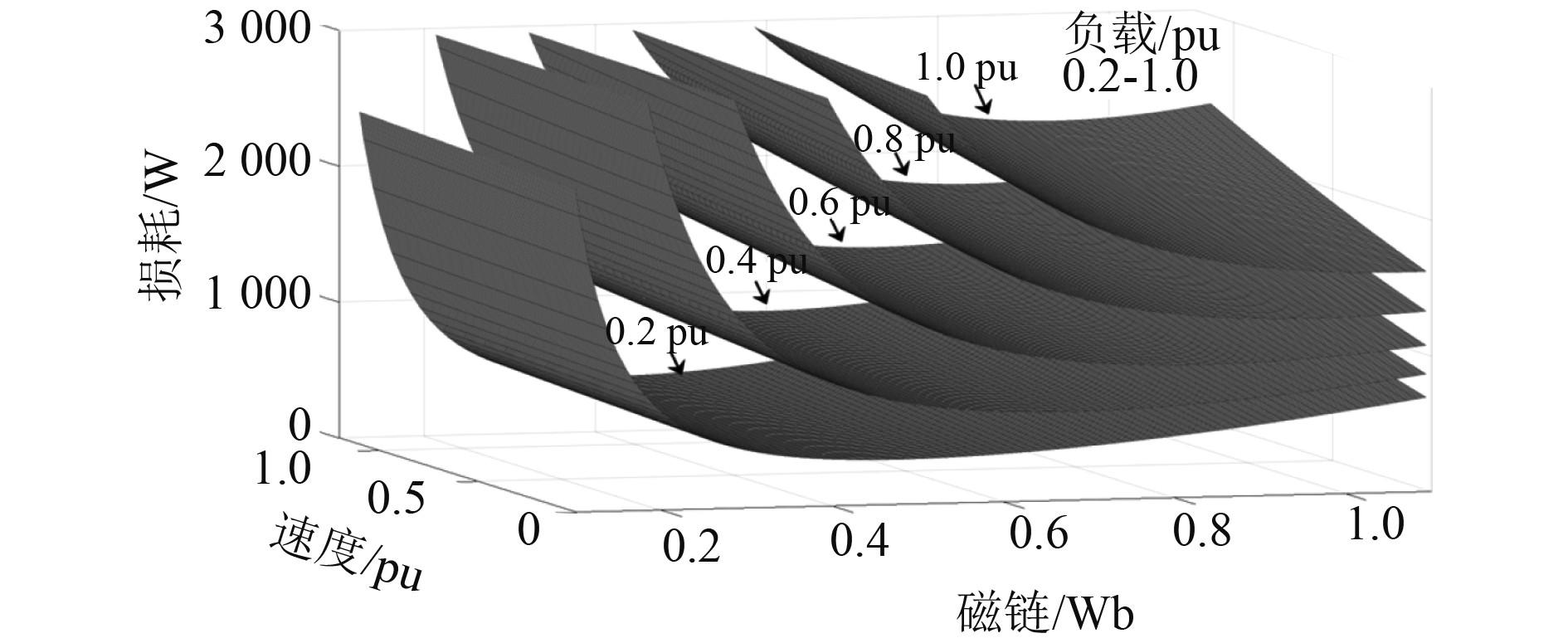
因此,当速度和负载确定时,式(10)为损耗-磁链函数为恒正的凹函数。如图2所示,LIM总损耗在次级磁链在零点处有且仅有唯一的最小值。

|
图 2 损耗-磁链曲线 Fig. 2 Loss-flux curve |
参考磁链可以表示为:
| $ \psi_{t}^{*}=\sqrt[4]{\dfrac{A_{2}}{A_{1}}} 。$ | (13) |
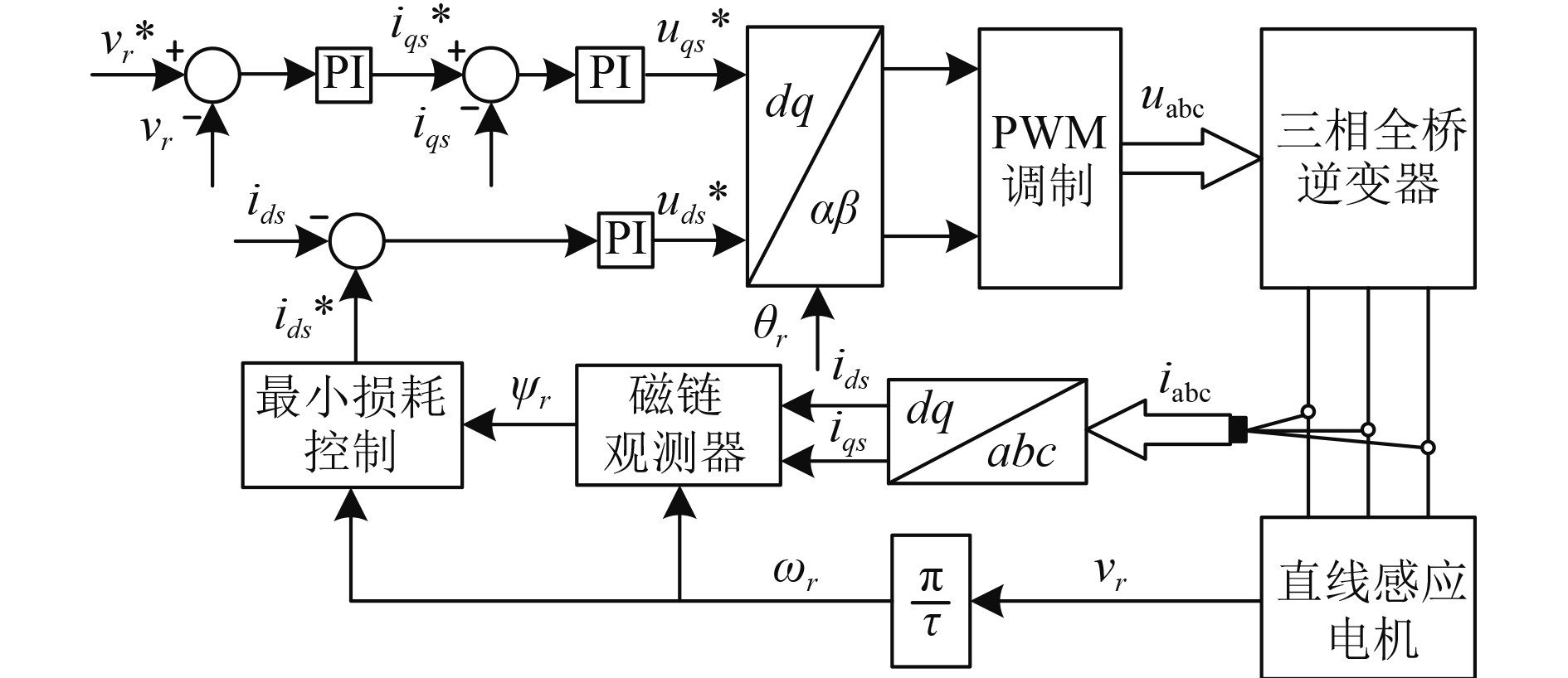
最小损耗控制策略拓扑图如图3所示。

|
图 3 LMC策略拓扑图 Fig. 3 LMC strategy topology |
基于理论分析,利用Matlab仿真软件对1台额定功率为3kW的LIM进行仿真研究,对比其在常规的FOC控制以及本文提出的新型LMC控制下的损耗变化以及LIM运行状态。仿真所采用的LIM主要参数如表1所示。
|
|
表 1 仿真的LIM主要参数 Tab.1 Main parameters of the simulated LIM |
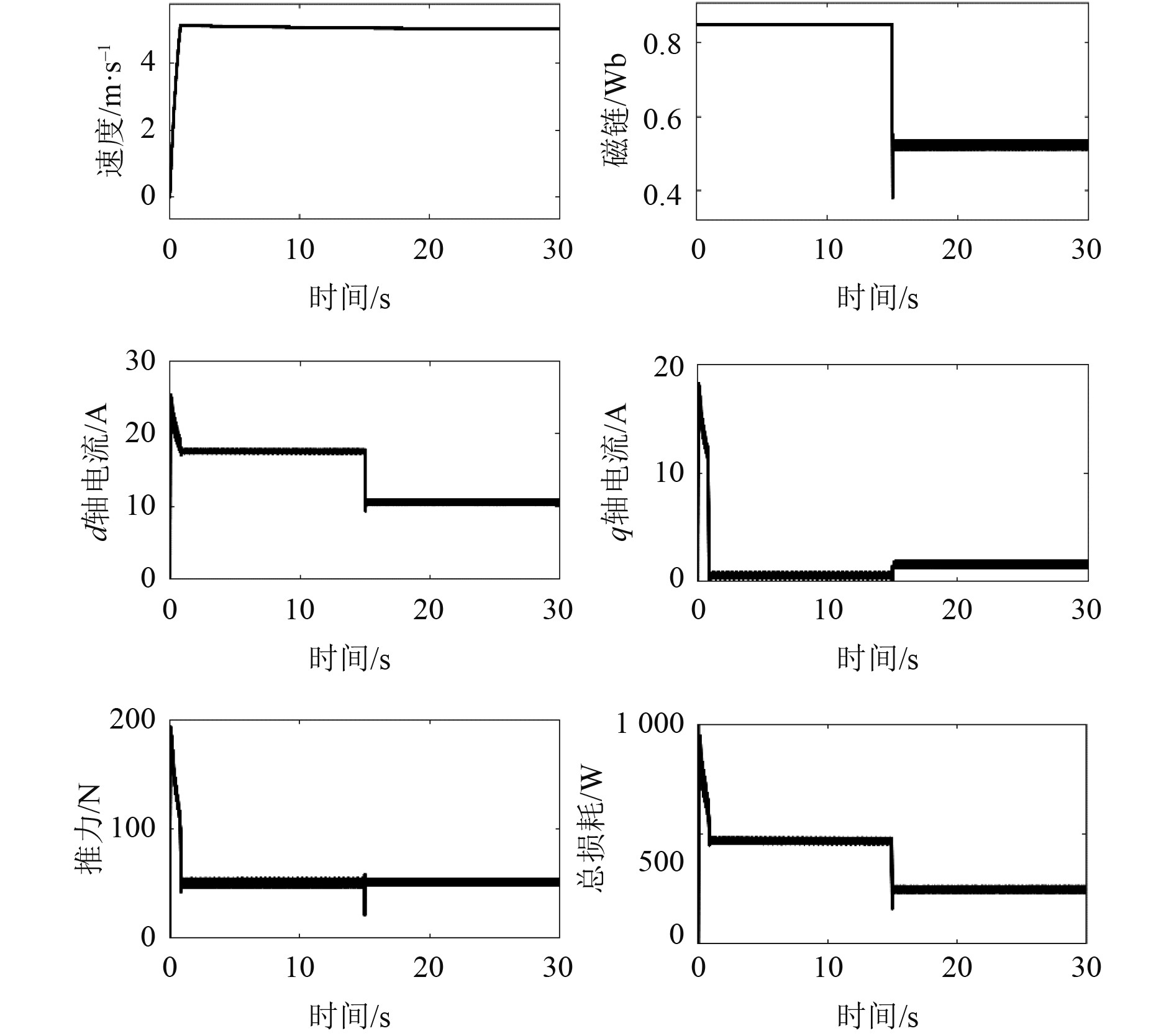
传统的FOC控制是基于恒定励磁的,而该励磁根据额定工况确定,这需要较大的d轴电流维持,所以轻载工况效率低下,因此在轻载时损耗对比更加清晰,仿真时负载设置为0.2 p.u.。启动和加速阶段采用FOC控制方式,恒定磁链设置为0.85 Wb,经过1.8 sLIM到达稳态,此时速度为5 m/s。由于主要研究稳态工况下的损耗,忽略加速过程。仿真总时长设置为30 s,运行到15 s时,控制策略从FOC切换成LMC。从而得到2种控制方式下电机速度、次级磁链、d-q轴电流、电机推力和总损耗对比,如图4所示。

|
图 4 负载0.2p.u.、5 m/s工况下FOC与LMC策略对比 Fig. 4 Comparison of FOC and LMC strategies under load 0.2p.u., 5 m/s |
可以看出,当控制策略切换为LMC,LIM的速度和推力都经历了短暂的波动,之后快速回到切换之前的稳态,可见电机仍然能维持当前的工作性能。而磁链下降使得d-q轴电流经过电流PI调节器调节平衡后达到新的稳态。重新平衡d-q轴电流后,q轴电流从1.3 A上升至2.3 A,d轴电流从16.8 A下降至10.4 A。LIM总损耗从486 W降低至266 W,减少了220 W,占总损耗的43%,可见损耗显著降低。
4 结 语为了解决LIM应用中提高效率的需求及当前损耗模型LMC策略存在的模型准确性和计算复杂度难以取舍的问题,提出了一种新型的综合考虑动态边端效应和漏感影响的LMC策略。在保证模型准确性的同时显著降低了计算复杂度,通过与常规的FOC控制方式进行仿真对比,验证了该策略的有效性,并且可知在轻载工况下损耗降低效果明显。
| [1] |
XU Wei, HU Dong, LEI Gang, et al. System-level efficiency optimization of a linear inductionmotor drive system[J]. CES Transactions on Electrical Machines and Systems, 2019, 3(3): 285-291. DOI:10.30941/CESTEMS.2019.00037 |
| [2] |
BAZZI A M, KREIN P T. A survey of real-time power-loss minimizersfor induction motors[C]//IEEE Electric Ship Technologies Symposium, 2009: 98-106.
|
| [3] |
BAZZI A M, KREIN P T. Review of methods for real-time loss minimization in induction machines[J]. IEEE Transactions on Industry Applications, 2010, 46(6): 2319-2328. DOI:10.1109/TIA.2010.2070475 |
| [4] |
MEEKER D C, NEWMAN M J. Indirect vector control of a redundant linear induction motor for aircraft launch[J]. Proceedings of the IEEE, 2009, 97(11): 1768-1776. DOI:10.1109/JPROC.2009.2030232 |
| [5] |
UDDIN M N, NAM S W. New online loss-minimization-based control of an induction motor drive[J]. IEEE Transactions on Power Electronics, 2008, 23(2): 926-933. DOI:10.1109/TPEL.2007.915029 |
| [6] |
SHREELAKSHMI M P, AGARWAL V. Trajectory optimization for loss minimization in induction motor fed elevator systems[J]. IEEE Transactions on Power Electronics, 2017, 33(6): 5160-5170. |
| [7] |
LIU J, FEI L, HU S, et al. Optimal efficiency control of linear induction motor drive for linear metro[C]//Power Electronics Specialists Conference, IEEE, 2007.
|
| [8] |
REN J Q, LI Y H, XU W, et al. Loss model establishment and efficiency optimization control of single sided linear induction motor[C]//IEEE International Conference on Industrial Technology, IEEE, 2008.
|
| [9] |
KIM D, KWON B. A novel equivalent circuit model of linear induction motor based on finite element analysis[C]//INTERMAG 2006-IEEE International Magnetics Conference, 2006: 503–503.
|
| [10] |
DONG H, WEI X, DIAN R, et al. Improved loss model and loss minimization control strategy for linear induction machine[C]//2017 IEEE Applied Power Electronics Conference and Exposition (APEC), IEEE, 2017.
|
| [11] |
HAN Y, NIE Z, XU J, et al. Mathematical model and vector control of a six-phase linear induction motor with the dynamic end effect[J]. Journal of Power Electronics, 2020, 20(3): 698-709. DOI:10.1007/s43236-020-00059-x |
| [12] |
ZHAO Y, LIPO, T. A. Space vector PWM control of dual three-phase induction machine using vector space decomposition[J]. IEEE Transactions on Industry Applications, 1995.
|
 2023, Vol. 45
