船舶型线优化设计是指通过对船舶的外形和型线进行优化,以提高船舶的性能和效率。船舶型线优化设计的目标是减小船舶的阻力,提高航行速度、节省燃油消耗和减少排放,同时保持船舶的稳定性和安全性。通常船舶阻力主要包括摩擦阻力、波浪阻力和空气阻力等,在船舶型线优化时,可以通过调整船舶的船首形状、船尾形状和船体的横截面形状等来优化船舶的船型,减小波浪阻力和空气阻力。通过调整船舶的长宽比、船舶的吃水深度和船舶的排水量等来优化船舶的船体尺寸,提高航行速度和节省船舶的燃油消耗。
船舶型线优化设计是一个多目标寻优问题,本文以非均匀有理B样条(NURBS样条)为优化的基础,使用计算机辅助软件进行船舶的流体动力学特性分析,对船舶型线优化的阻力特性进行了有限元仿真。
1 NURBS样条曲线的基本研究NURBS样条是由一系列控制点、权重和节点向量定义的,其中,控制点确定了曲线或曲面的形状,权重用于调整控制点对曲线或曲面的影响程度,节点向量决定了曲线或曲面的参数化方式。与其他样条方法相比,NURBS样条具有以下特点:
1)非均匀性。节点向量可以非均匀地分布,使得曲线或曲面在不同区域具有不同的密度,从而更好地适应复杂形状。
2)有理性。NURBS样条允许控制点具有不同的权重,通过调整权重可以改变曲线或曲面的形状,使得NURBS样条能够表示更广泛的曲线和曲面。
3)局部控制性。修改一个控制点只会影响曲线或曲面的局部区域,不会对整个曲线或曲面产生影响,这使得NURBS样条更易于编辑和调整[1]。
NURBS样条的定义如下:
定义控制点矢量
| $ \left\{ {\begin{array}{*{20}{l}} {{{{N}}_{i,0}}({{t}}) = \left\{ {\begin{array}{*{20}{l}} 1,& {{{t}}_i} \leqslant {{t}} < {{{t}}_{i + 1}},\\ 0,& {\rm{else}} ,\end{array}} \right.} \\ {{{{N}}_{i,p}}({{t}}) = \dfrac{{{{t}} - {{{t}}_i}}}{{{{{t}}_{i + p}} - {{{t}}_i}}}{{{N}}_{i,p - 1}}({{t}}) + \dfrac{{{{{t}}_{i + p + 1}}}}{{{{{t}}_{{{i}} + 1}}}}{{{N}}_{i + 1,p - 1}}(t)} ,{{\rm{else}}} 。\end{array}} \right. $ |
式中:
NURBS样条的曲线方程可改写为:
| $ \begin{gathered} p(u) = \sum\limits_{i = 0}^n {{d_i}} {R_{i,p}}(u) \text{,} \\ {R_{i,p}}(u) = \frac{{{\omega _i}{N_{i,p}}(u)}}{{\displaystyle\sum\limits_{j = 0}^n {{\omega _i}} {N_{i,p}}(u)}}\text{。} \\ \end{gathered} $ |
式中:p为NURBS样条的幂次;
NURBS样条的特性函数表达式如下:
1)递推特性
| $ {{\text{N}}_{i,p}}({\text{t}}) = F\left( {{{\text{N}}_{{\text{i}},p - 1}}({\text{t}})} \right) \text{,} $ |
2)归一性
| $ \sum\limits_{i = 0}^n {{N_{i,p}}} (t) = 1 。$ |
3)局部区间支撑性[2]
| $ {N_{t,p}}(t)\left\{ {\begin{array}{*{20}{l}} { \geqslant 0},&{t \in \left[ {{t_i},{t_{i + p + 1}}} \right]},\\ { = 0},&{{\text{else}}} 。\end{array}} \right. $ |
4)非负性
| $ {N_{t,p}}(t) \geqslant 0 。$ |
基于NURBS样条的曲线构造过程如下:
1)分别构造曲线
2)估算单条曲线长度占整个曲线的占比,记为
3)将曲线
4)连接控制多边形的节点矢量,产生拟合曲线。
图1为基于NURBS样条的曲线拟合实例,节点矢量AB之间的直线与拟合后的曲线最大距离为0.325。

|
图 1 基于NURBS样条的曲线拟合实例 Fig. 1 An example of curve fitting based on NURBS splines |
船舶型线的设计优劣直接影响船体在航行过程的阻力,为了准确分析舰船型线与阻力特性的关系,对船舶的水动力-阻力特性进行研究。
首先建立船舶水动力分析的基础理论方程如下:
1)连续性方程
| $ \frac{{{\rm{d}}{\rho_0}}}{{{\rm{d}}t}}+{\rho_0}\Delta \cdot V = 0 \text{,} $ |
式中:
2)雷诺方程
| $ \left\{ {\begin{array}{*{20}{l}} {{\rho _0}\dfrac{{{\rm{d}}{V_x}}}{{{\rm{d}}t}} = \dfrac{{\partial \sigma }}{{\partial x}} + {\rho _0}f} ,\\ {\dfrac{{\partial \rho {V_x}}}{{\partial t}} + \dfrac{{{\partial ^2}(P)}}{{\partial x}} = \dfrac{{\delta P}}{{\delta x}} + \dfrac{\partial }{{\partial {V^2}}}\left(\delta \dfrac{{\partial {V_y}}}{{\partial X}}\right) - Q} 。\end{array}} \right. $ |
式中:
海水的流场速度势满足:
| $ \psi \left( {x,y} \right) = - kV + {\varphi _c} \text{,} $ |
式中,
| $ {\varGamma ^2}\psi \left( {x,y} \right) = 0 。$ |
3)能量方程
| $ {\rho _0}\frac{{{\rm{d}}E}}{{{\rm{d}}t}} = - {\rho _0}\Delta \cdot V + Q - \Delta q \text{。} $ |
式中:
4)船舶运动建模
定义船舶运动坐标系的原点为重心位置处,OX轴与运动方向平行;OZ轴垂直于甲板平面,指向上方,OY轴指向船舶的左舷,建立船舶运动方程为:
| $ \left\{ {\begin{array}{*{20}{c}} {m\left( {u - rv} \right) = {M_x}}\text{,} \\ {m\left( {v - ru} \right) = {M_y}} \text{,}\\ {{J_x}r = {M_x} - {M_y}\cos \alpha } \text{。} \end{array}} \right. $ |
式中:
船舶表面的流体-固体物面条件可写为:
| $ \frac{{{\partial }\psi }}{{\partial n}} - Vn = 0 \text{,} $ |
可得单位流体的垂向速度为:
| $ {v_n} = \frac{{{k_1}{v_x} + {k_2}{v_y}}}{{\sqrt {{H_x}^2 + {H_y}^2} }} 。$ |
式中:
最终得到船舶阻力方程为:
| $ F(X,Y,t) = A\cos \left( {\frac{{2\text{π} }}{\lambda }\left( {Y\cos \theta + X\sin \theta - {v_n}t} \right)} \right) 。$ |
式中:
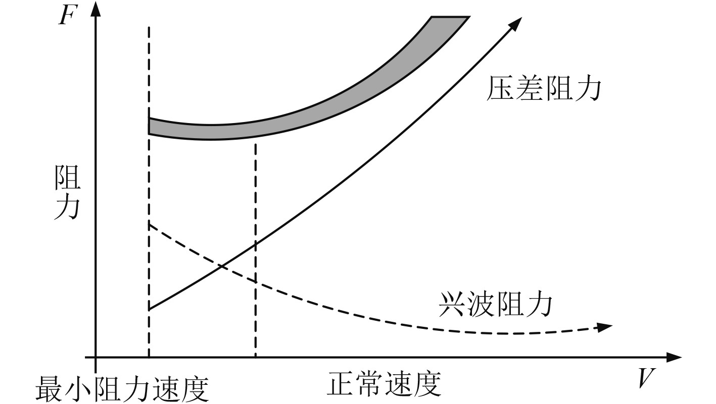
船舶航行速度与阻力之间的关系曲线如图2所示。

|
图 2 船舶航行速度与阻力之间的关系曲线 Fig. 2 The curve of the relationship between the speed of a ship and its resistance |
可知,随着航行速度的增加,兴波阻力逐渐下降,而压差阻力逐渐增加。
2.2 基于NURBS样条的船舶型线和曲线优化设计基于NURBS样条进行船舶剖切面型线和船体曲面的优化。
1)船舶尾部剖切面型线
首先建立船舶主体尺寸的变换函数为:
| $ \begin{array}{*{20}{l}} {{X_t} = \lambda {X_O}} \text{,}\\ {{Y_t} = \beta {Y_O}} \text{,}\\ {{Z_t} = \gamma {Z_O}} \text{。} \end{array} $ |
式中:
在剖切面型线优化过程中[5],船舶主体尺寸的变换函数保持不变,建立剖切面的型线公式如下:
| $ {f_P} = \left\{ {\begin{array}{*{20}{l}} {{R_1} = {k_i} \times {B_0}\sin {\alpha _1}} \text{,} \\ {{R_2} = \left( {y_d/2 - {k_t}} \right)\tan {\alpha _2} - {D_0}} 。\end{array}} \right. $ |
其中:
船舶尾部剖切面型线的数学模型如图3所示。

|
图 3 船舶艉部剖切面型线的数学模型 Fig. 3 Mathematical model of ship stern section profile |
图中,R1为船身中心线水上部分,R2为壳体型线。
2)船舶曲面构造
船体曲面由无数曲线构成,首先基于NURBS样条建立船体型线的节点为:
| $ {V_{i,j}}\left( {i = 0,1,...,m;j = 0,1,...,n} \right) \text{,} $ |
得到型线的节点方向矢量为:
| $ \begin{gathered} F = \{ \underbrace {0,{t_{p + 1}}, \cdots ,{t_n},1}_{p + 1}\},\\ K = \{ \underbrace {0,{w_{q + 1}}, \cdots ,{w_n},1}_{q + 1}\} 。\\ \end{gathered} $ |
根据型线和节点矢量建立曲面如下:
| $ S(F,K) = \sum\limits_{i = 0}^n {\sum\limits_{j = 0}^n {{N_{i,p}}(F)} } {N_{j,p}}(K){V_{i,j}} 。$ |
式中,
针对船舶型线优化前后的阻力特性,本文采用了CFD计算流体力学分析软件Fluent进行仿真,仿真的波浪载荷如下:
| $ f = {\varphi _0}\cos \left( {kx - {w_0}t} \right) 。$ |
其中:
CFD仿真采用的边界参数如表1所示。
|
|
表 1 CFD仿真采用的边界参数 Tab.1 Boundary parameters used in CFD simulation itial input parameter table of simulation program |
仿真得到船舶型线优化前A和优化后B的阻力特性如图4所示。

|
图 4 船舶型线优化前后的阻力特性 Fig. 4 Resistance characteristics of ship profile before and after optimization |
可知,经过船舶型线优化后的船舶仿真中,阻力特性有明显的降低。
3 结 语船舶型线设计与船舶的流体动力学性能息息相关,本文基于NURBS样条进行船体型线的优化设计,同时结合计算流体力学(CFD)分析、有限元分析等工具,进行了型线优化的仿真分析。基于计算机辅助的船舶型线设计是一种高效、精确和可靠的设计方法,可以更好地设计和优化船舶的外形和型线,以满足船舶的性能和要求。
| [1] |
段亦隆, 苏绍娟, 马立天, 等. 基于船舶阻力近似模型的球艏与舭部优化设计[J]. 船舶工程, 2022, 44(8): 59-65+72. DUAN Yi-long, SU Shao-juan, MA Li-tian, et al. Optimal design of ball bow and bilge based on approximate ship resistance Model[J]. Ship Engineering, 2022, 44(8): 59-65+72. |
| [2] |
柴梦竹. 基于CATIA的船舶型线设计与仿真[J]. 舰船科学技术, 2018, 40(18): 16-18. CHAI Meng-zhu. Ship Profile Design and Simulation based on CATIA[J]. Ship Science and Technology, 2018, 40(18): 16-18. |
| [3] |
芮广亚. 非线性规划算法在船舶型线优化中的应用[J]. 舰船科学技术, 2018, 40(2): 10-12. RUI Guang-ya. Application of nonlinear programming Algorithm in Ship profile optimization[J]. Ship Science and Technology, 2018, 40(2): 10-12. |
| [4] |
段菲, 张利军, 陈鸽, 等. 基于多目标优化算法NSGA Ⅱ的极地穿梭油轮型线设计[J]. 中国舰船研究, 2017, 12(6): 66-72. DUAN Fei, ZHANG Li-jun, CHEN Ge, et al. Polar shuttle tanker profile design based on multi-objective optimization algorithm NSGAⅡ[J]. Chinese Ship Research, 2017, 12(6): 66-72. |
| [5] |
兰林强, 罗伟林. 基于参数化建模和CFD数值模拟的船舶球鼻艏优化设计[J]. 机电工程, 2016, 33(11): 1329-1333+1353. LAN Lin-qiang, LUO Wei-lin. Optimization design of ship bulb bow based on parametric modeling and CFD numerical simulation[J]. Mechanical and Electrical Engineering, 2016, 33(11): 1329-1333+1353. |
| [6] |
徐青, 姜治芳, 杜月中. 综合试验船船型优化设计及试验研究[J]. 华中科技大学学报, 2001(9): 54-56. XU Qing, JIANG Zhi-fang, DU Yue-zhong. Optimization design and experimental research of comprehensive test ship[J]. Journal of Huazhong University of Science and Technology, 2001(9): 54-56. |
 2023, Vol. 45
