2. 清华大学 核能与新能源技术研究院 先进反应堆工程与安全教育部重点实验室,北京 100084
2. Key Laboratory of Advanced Reactor Engineering and Safety of Ministry of Education, Institute of Nuclear and New Energy Technology, Tsinghua University, Beijing 100084, China
一体化自然循环反应堆设计具有系统简化,能动部件少和噪声低等优点。但是自然循环的冷却方式导致其存在反应堆流动强度和换热效率较低,流动和传热特征变化敏感较强等特征[1-4],在诸如大幅度变化功率或者倾斜摇摆等外部条件变化时,存在大量与系统特性相关的动态响应过程。对于在复杂工况下,多种不稳定性因素共同作用的耦合情况,目前缺乏系统性的认识和结论。本文建立一体化自然循环反应堆典型分析模型,并通过对其数值建模,开展自然循环系统摇摆耦合升功率条件下的不稳定性影响研究。
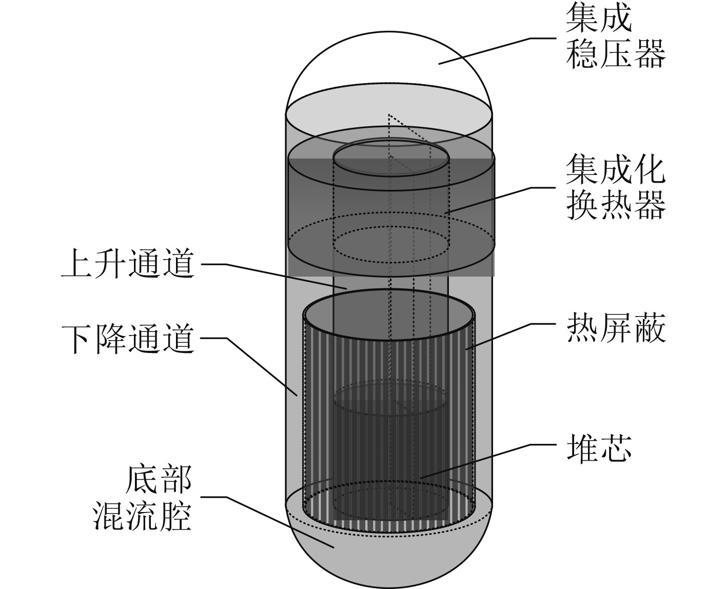
1 一体化小型自然循环反应堆典型模型综合目前国际上典型的一体化自然循环反应堆设计方案[5-16],选择3∶1高径比的圆柱形压力壳结构建立分析模型,基本结构如图1所示。
|
图 1 三维分析模型结构示意图 Fig. 1 Schematic diagram of typical 3d analysis model |
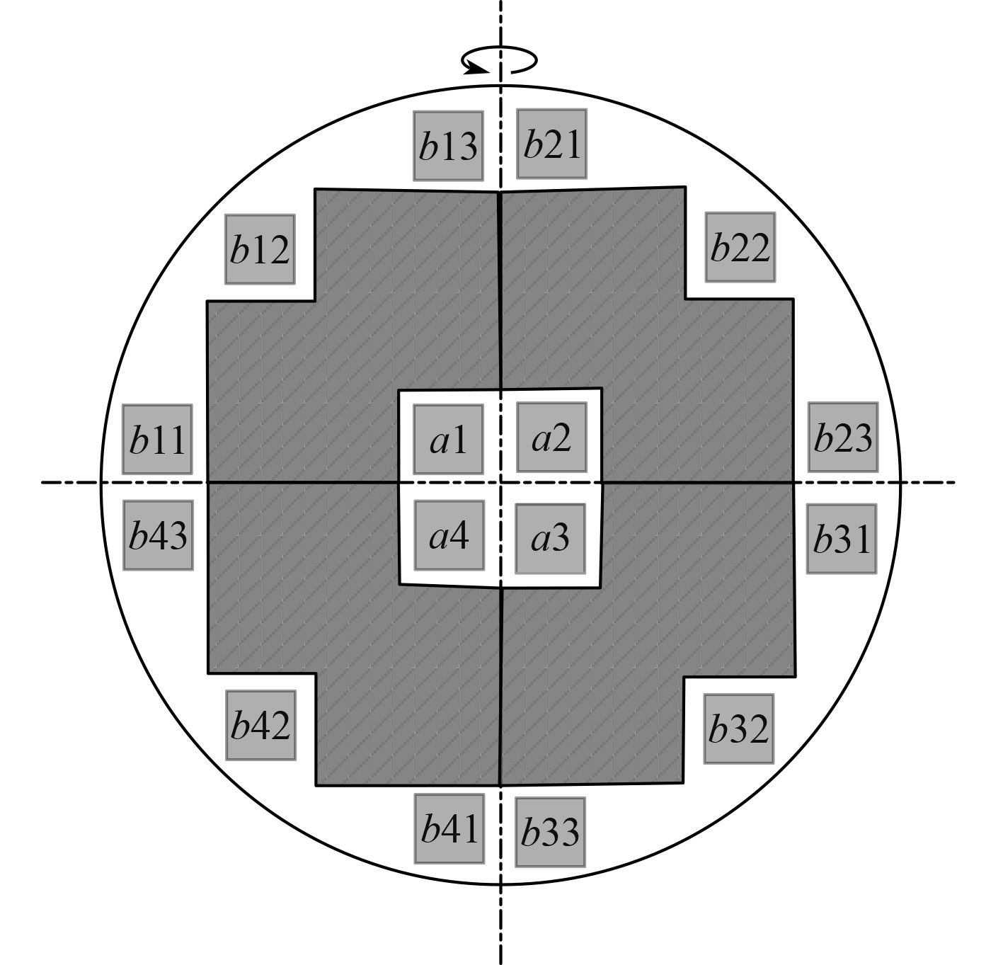
对于自然循环反应堆这一大尺度三维系统,为了建模和分析方便,模拟堆芯采用了简化设计方案,模拟堆芯横剖面结构如图2所示。
|
图 2 典型堆芯剖面结构示意图 Fig. 2 Schematic diagram of typical core profile structure |
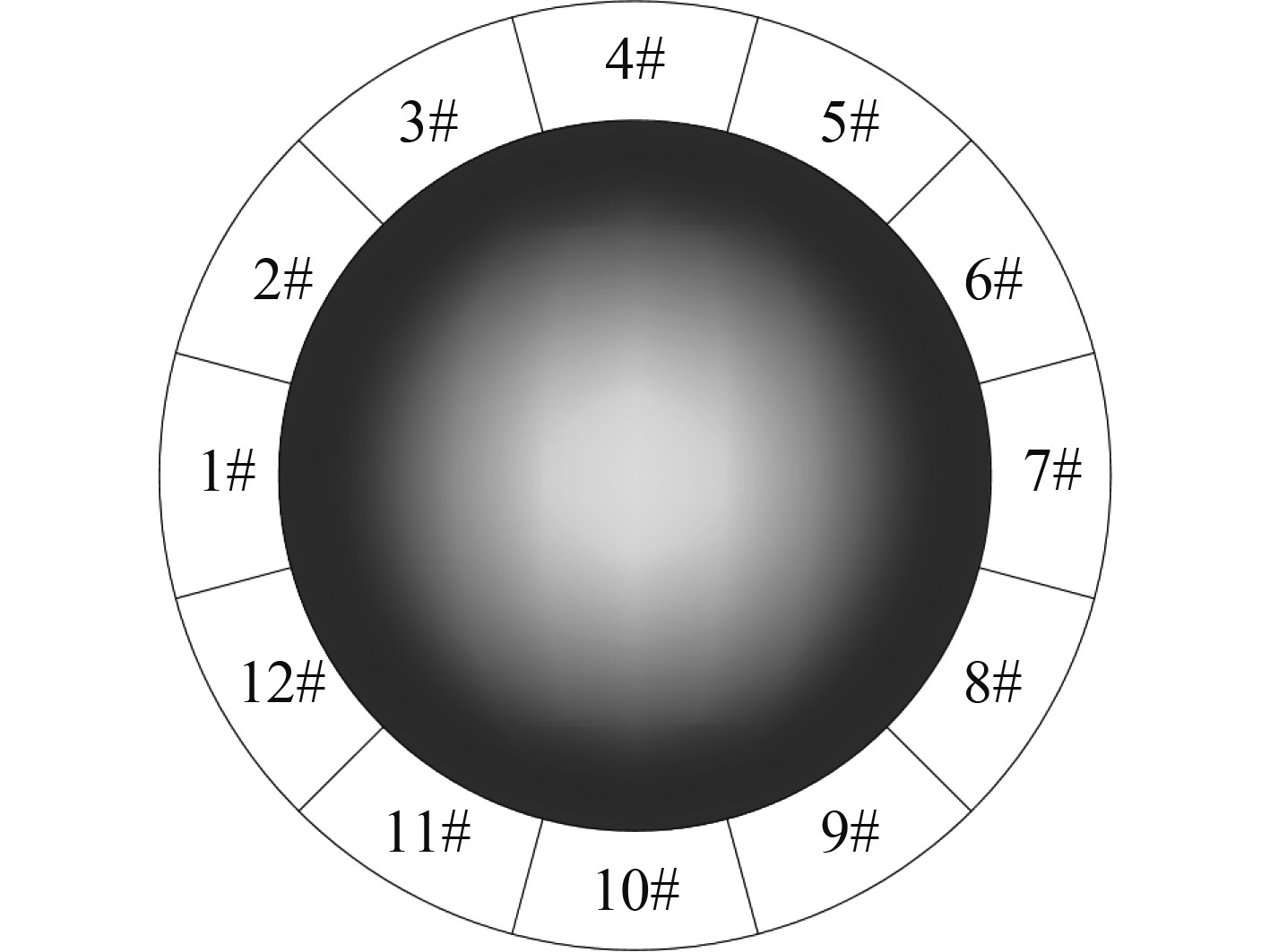
模型采用堆芯分区设计方案,按8×8燃料棒设计方案对应通道结构尺寸确定子通道结构尺寸。中心区域(a区)采用4个正交的子通道进行模拟,外围区域(b区)采用对应平面空间4个象限中各设置间隔45°布置的3个子通道。斜线区域采用各向异性多孔介质模型。换热器布置在堆芯及其上方的上升通道外围通道顶部,采用对称分区方案,按30°间隔将换热器一周等间隔划分为12组并联的换热器流道,如图3所示。
|
图 3 典型换热器结构示意图 Fig. 3 Schematic diagram of typical heat exchanger structure |
CFD计算依据基本的控制方程组,描述流体系统中的质量、动量和能量守恒关系。
质量守恒方程
| $ \frac{\partial \rho}{\partial t}+\nabla \cdot(\rho \vec{u})=S_{m},$ | (1) |
动量守恒方程
| $ \frac{\partial}{\partial t}(\rho \vec{u})+\nabla \cdot(\rho \vec{u} \vec{u})=-\nabla p+\nabla \cdot(\bar{\bar{\tau}})+\rho \vec{g}+\vec{F},$ | (2) |
能量守恒方程
| $ \begin{split} &\frac{\partial}{\partial t}(\rho E)+\nabla \cdot[\vec{u}(\rho E+p)] =\\ &\qquad\quad \nabla\left[k_{{eff}} \nabla T-\sum_{i} h_{i} \vec{J}_{i}+\left(\bar{\bar{\tau}}_{{uff }}+\vec{u}\right)\right]+S_{h}。\end{split} $ | (3) |
式中,应力张量定义为
| $ \bar{\bar{\tau}}=\mu\left[\left(\nabla \vec{u}+\nabla \vec{u}^{{\rm{T}}}\right)-\frac{2}{3} \nabla \cdot \vec{u} I\right],$ | (4) |
单位密度能量系数表示为
| $ E=h-\frac{p}{\rho}+\frac{u^{2}}{2}。$ | (5) |
比焓项对于理想气体和不可压缩流体分别定义如下:
1) 理想气体条件
| $ h=\sum_{i} \psi_{i}\left(\int_{T ref}^{T} Cp_{i} {\rm{d}} T\right) ,$ | (6) |
2) 不可压缩流体条件
| $ h=\sum_{i} \psi_{i}\left(\int_{Tref}^{T} Cp_{i} {\rm{d }}T\right)+\frac{p}{\rho} ,$ | (7) |
式中,
采用平衡态能量控制方程计算换热器处的传热量:
| $ \begin{split} &\frac{\partial}{\partial t}\left[\gamma \rho_{f} E_{f}+(1-\gamma) \rho_{s} E_{s}\right]+\nabla \cdot\left[\vec{u}\left(\rho_{f} E_{f}+p\right)\right] =\\ &\qquad S_{f}^{h}+\nabla \cdot\left[k_{e f f} \nabla T-\left(\sum_i h_{i} J_{i}\right)+(\bar{\bar{\tau}} \cdot \vec{u})\right]。\end{split} $ | (8) |
式中:
| $ k_{e f f}=\gamma k_{f}+(1-\gamma) k_{s} 。$ | (9) |
反应堆数值模型采用六面体结构化网格的分区设计方案,主要圆形流道采用O-Grid类型网格,小尺寸圆形流道采用结构化和非结构化混合网格,换热器流道采用圆管结构。选用二阶迎风格式作为流场的空间离散格式,根据控制单元中心状态参数插值计算单元界面处的通量参数值;选择PISO算法作为模型的数值求解方法;采用RNG k-ε模型模拟湍流。
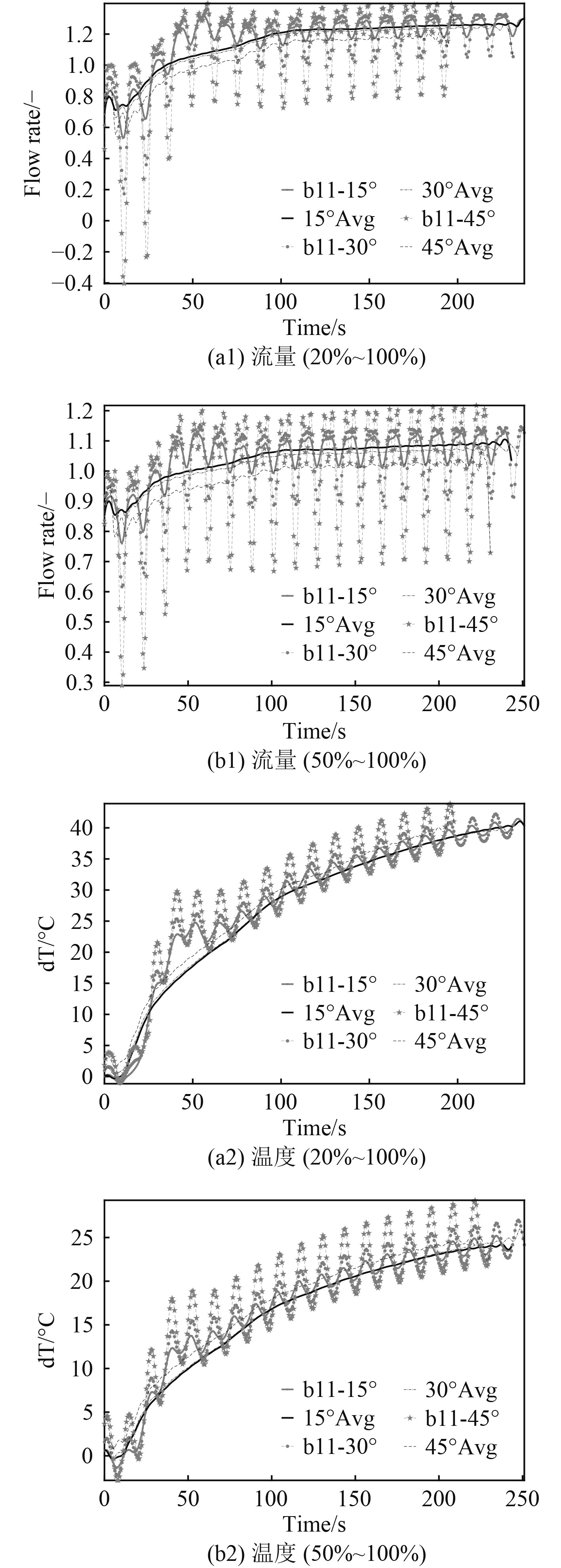
3 瞬态过程参数变化情况通过数值模型,以对应0°方位的堆芯流道b11和换热器HEX-1为例,通过分析13 s周期,15°、30°和45°最大摆角条件下的功率瞬态过程参数变化情况。研究大幅升功率(功率水平由20%经30 s提升至100%)和中幅升功率(功率水平由50%经30 s提升至100%)耦合不同摇摆条件的瞬态过程参数变化情况。
3.1 堆芯温度和流量变化图4为升功率过程堆芯流量和温度变化曲线。对应0°方位的堆芯流道,当功率提升速率较大,基础温度相对较低时,通道中温度和流量的波动幅度,瞬态过程初期强于而后期弱于相对功率提升速率较低的工况相应结果。这说明在功率提升速率更快的情况下,虽然初期可能参数波动较大,但是后期更容易趋于稳态。这是由于功率提升幅度大,单位时间内总传热量增加,导致流体升温速率提高。
|
图 4 升功率过程堆芯流量和温度变化曲线 Fig. 4 Flow and temperature during power raising process |
在功率提升的前期阶段,大幅升功率工况对应的温度和流量存在更为明显的“过冲”现象,即初期流量和温度参数上升速率远大于后期,且在中间甚至呈现负上升速率特性的非单调变化情况。该现象的出现是,由于系统流体存在流动和热惯性,初期功率提升后原有自然循环系统流量变化存在延迟,导致堆芯流体温度突然升高,自然循环驱动力瞬时激增。后续当自然循环逐渐回归稳态时,温升速率回归正常水平,则该强化自然循环瞬态也回复正常变化情况。
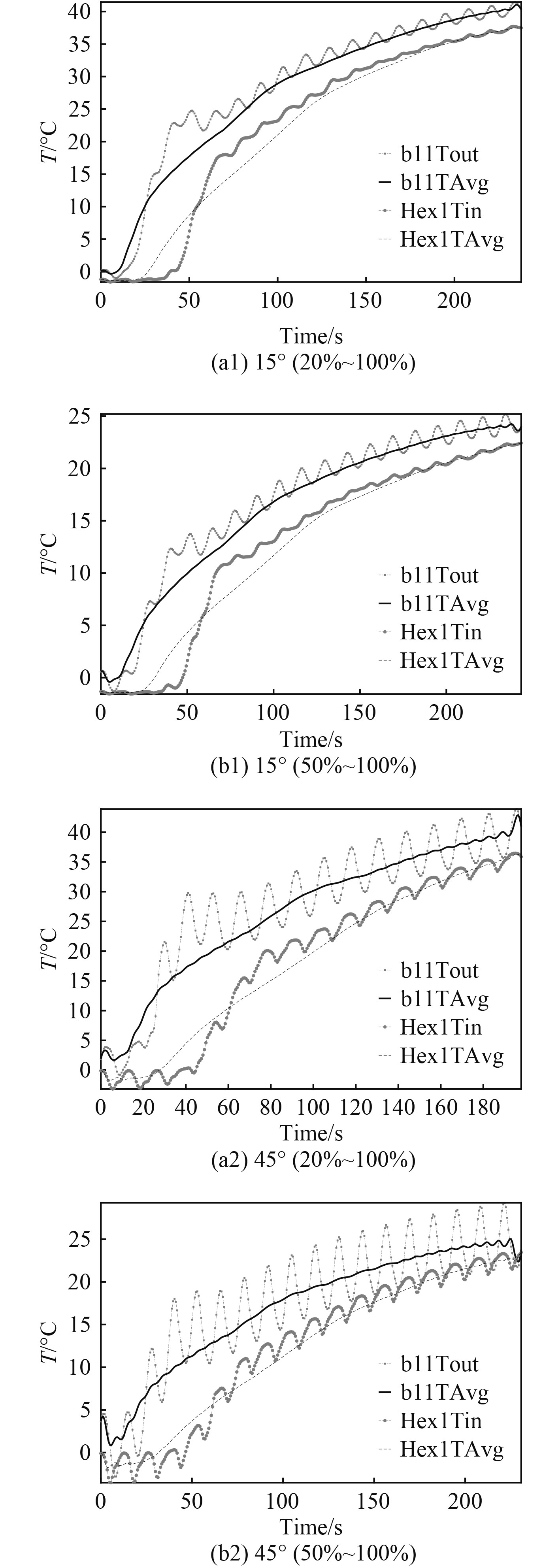
3.2 回路温度变化图5为不同功率上升速率,以及不同最大摇摆角度耦合的工况下,堆芯出口温度和换热器入口温度之间的差异,及其随功率上升瞬态的变化情况。升功率过程中,堆芯出口温度始终高于换热器入口温度,两者温差先增大再减小。功率提升瞬态过程中,堆芯出口温度波动始终大于换热器入口温度波动。这是顶部混流腔中不同堆芯通道的不同温度流体预混合导致的效果,说明顶部混流腔有抑制系统温度波动的能力。
|
图 5 堆芯出口与换热器入口温度变化曲线 Fig. 5 Temperature of core outlet and heat exchanger inlet |
对应相同升功率幅度工况,最大摆角越大,初期堆芯出口与换热器入口温差越大,且较大温差保持的时间也较长。当系统摇摆角度增大时,堆内结构壁面与流体之间换热增强,进而导致堆芯上方流道温度较堆芯出口下降更快,从而使换热器通道受到堆芯加热影响的延迟时间更长。
较大的摇摆角度会通过增加热通道等效密度的方式,削弱自然循环驱动力。该作用与重力驱动高差随摆角增大而减小的影响共同作用于流体系统,导致大摆角条件下的自然循环流量降低幅度超过线性变化条件下的相应降低幅度水平。该因素对应作用于不同功率上升程度的影响程度,近似与功率上升幅度呈现线性比例变化特性关系。
4 结 语对于海上电站等浮动平台中自然循环反应堆,海洋条件造成的摇摆与功率变化条件相耦合所造成的流动不稳定性,将直接影响电站的效率和安全性,本文针对针对这一问题,以一体化自然循环小型反应堆为对象进行CFD数值模拟研究,得到以下结论:
1)在功率提升的前期阶段,大幅升功率工况对应的温度和流量存在更为明显的“过冲”现象,即初期流量和温度参数上升速率远大于后期,且在中间甚至呈现负上升速率特性的非单调变化情况;
2)由于摇摆强化了上升传热部件内部壁面换热热通量,大摆角的工况下,堆芯和换热器部分温度变化幅度均强于较小摆角的工况,相应的部件进出口温差也保持较高水平;
3)顶部混流腔有抑制系统温度波动的作用。
| [1] |
STENNING A H, VEZIROGLU T N. Flow oscillations models in forced convection boiling [R]. Proceeding of Heat Transfer and Fluid Mechanics Institute, Stanford University Press, 1965, 301.
|
| [2] |
LAHEY R T. An assessment of the literature related to LWR instability modes[R]. NUREGCR, 1980: 144.
|
| [3] |
KAKAÇ S, BON B. A Review of two-phase flow dynamic instabilities in tube boiling system[J]. International journal of heat and mass transfer, 2008, 51: 399-433. |
| [4] |
FUKUDA K, KOBORL T. Classification of two-phase instability by density wave oscillation model[J]. Journal of Nuclear Society and Technology, 1979, 16(2): 85-108. |
| [5] |
IAEA. Passive safety systems and natural circulation in water cooled nuclear power plants, IAEA-TECDOC-1624[R]. Austria: International Atomic Energy Agency, 2009.
|
| [6] |
张亚军, 王秀珍. 200 MW低温核供热堆研究进展及产业化发展前景[J]. 核动力工程, 2003, 24(2): 180-183. DOI:10.3969/j.issn.0258-0926.2003.02.019 |
| [7] |
李卫华, 张亚军, 郭吉林, 等. 一体化核供热堆Ⅱ型的开发及应用前景初步分析[J]. 原子能科学技术, 2009, 43(Suppl.): 215-218. |
| [8] |
KIM J H, KIM T W, LEE S M, et al. Study on the natural circulation characteristics of the integral type reactor for vertical and inclined conditions[J]. Nuclear Engineering and Design, 2001, 207: 21-31. DOI:10.1016/S0029-5493(00)00417-9 |
| [9] |
CARELLI M D, CONWAY L E, ORIANI L, et al. The design and safety features of the IRIS reactor[J]. Nuclear Engineering and Design, 2004, 230(1-3): 151-167. DOI:10.1016/j.nucengdes.2003.11.022 |
| [10] |
SHIRVAN K, FORREST E. Design of an organic simplified nuclear reactor[J]. Nuclear Engineering and Technology, 2016, 48(4): 893-905. DOI:10.1016/j.net.2016.02.019 |
| [11] |
INGERSOLL D T, HOUGHTON Z J, BROMM R, et al. NuScale small modular reactor for co-generation of electricity and water[J]. Desalination, 2014, 340: 84-93. DOI:10.1016/j.desal.2014.02.023 |
| [12] |
SERDUN N P, IGNATENKO V I, KOTIKOV G S. Experimental studies into the thermal-hydraulic performance of the VK-300 reactor based on a draft tube model[J]. Nuclear Energy and Technology, 2015, 1(4): 288-295. DOI:10.1016/j.nucet.2016.02.018 |
| [13] |
BAYBAKOV D F, GODOVYKH A V, MARTYNOV I S, et al. The dependence of the nuclide composition of the fuel core loading on multiplying and breeding properties of the KLT-40S nuclear facility[J]. Nuclear Energy and Technology, 2016, 2(3): 183-190. DOI:10.1016/j.nucet.2016.07.008 |
| [14] |
HIBI K, ONO H, KANAGAWA T. Integrated modular water reactor (IMR) design[J]. Nuclear Engineering and Design, 2004, 230(1-3): 253-266. DOI:10.1016/j.nucengdes.2003.11.025 |
| [15] |
KIM Y S, BAE S W, CHO S, et al. Application of direct passive residual heat removal system to the SMART reactor[J]. Annals of Nuclear Energy, 2016, 89: 56-62. DOI:10.1016/j.anucene.2015.11.025 |
| [16] |
PRIEGO E, ALONSO G, VALLE E, et al. Alternatives of steam extraction for desalination purposes using SMART reactor[J]. Desalination, 2017, 413: 199-216. DOI:10.1016/j.desal.2017.03.018 |
 2023, Vol. 45
