2. 东北大学 机械工程与自动化学院,辽宁 沈阳 110819
2. School of Mechanical Engineering and Automation, Northeastern University, Shenyang 110819, China
船用燃气轮机因具备单机功率大、指令反应灵敏迅速、重量体积小、加速性和机动性好等优点,作为重要动力装置被现代舰船广泛应用[1]。作为舰船的核心,燃气轮机运行状态的健康程度直接关系着舰船的生命力。振动是动力机械装置必然存在的物理现象,然而振幅过大的不良振动可能造成设备的破损、失效。燃气轮机作为高精密旋转类动力设备,对部件、整体振动的要求更为严格。转子系统是燃气轮机的主要动力发生部件,也是设备本身振动的主要来源部件。转子系统因质量不平衡产生振动是不可避免或消除的。当质量不平衡发展到一定程度,将造成转子系统的不平衡振动,尤其是过一阶共振时的振动超出安全阈值的问题。现代旋转机械结构日益复杂、紧凑,过大的振动可能进一步造成转子与机匣、封严等结构发生碰摩,严重降低系统运行的安全裕度,所以对燃气轮机转子系统进行振动抑制具有重要意义。解决质量不平衡引发的振动的有效措施之一是重做动平衡[2-3],但停机重做动平衡势必会造成停航。有学者对转子在线动平衡进行了一定研究[4-5],但就目前实际效果来看研究结果具有一定局限性。除动平衡外,还尝试利用改变支承刚度[6]和阻尼[7-8]等手段对转子进行振动控制。吸振技术作为一种简谐振动的有效抑制措施,被应用于多种领域。许多研究人员对吸振器抑制转子振动进行了研究讨论。冯浩然等[9]利用一种新型质量调谐吸振器解决了多跨串联转子在升速降速过程中经过转子的临界转速区域会产生严重振动的问题。Taghipour等[10]对被动式吸振器抑制转子振动进行了研究,表明被动式吸振器可有效降低转子振动。Tehrani等[11]对利用安装在转子叶片顶端的被动式吸振器抑制转子振动进行了研究,表明吸振器可降低振动,消除叶片与定子之间的接触,降低转静子间碰摩故障的发生几率。曹焱博等[12]也设计了非线性吸振器对叶片转子进行振动抑制,研究表明安装在叶片内部的吸振器可对转子及叶片振动起到良好的抑制作用。BAB等[13]对非线性能量阱抑制燃气轮机转子振动进行了研究,结果表明非线性能量阱可在较宽转速范围内降低转子振动。DOU等[14]甚至实现了利用磁性吸振器有效抑制转子扭转振动。与单自由度主系统不同,船用燃气轮机转子系统是连续体结构,转轴上能够安装吸振器位置较多。上述研究中均未进行过安装位置对吸振器抑振效果影响的详细讨论,所以为了明确安装位置对吸振器参数及抑振性能的影响,本文采用有限元法对吸振器-转子耦合系统进行离散,利用拉格朗日方程进行动力学建模,抑制转子系统过一阶临界转速过大振动。采用文献[15]中的限边界坐标轮换法对安装在各节点的转子吸振器参数进行优化,分析安装位置与吸振器参数及抑振性能间的关系。
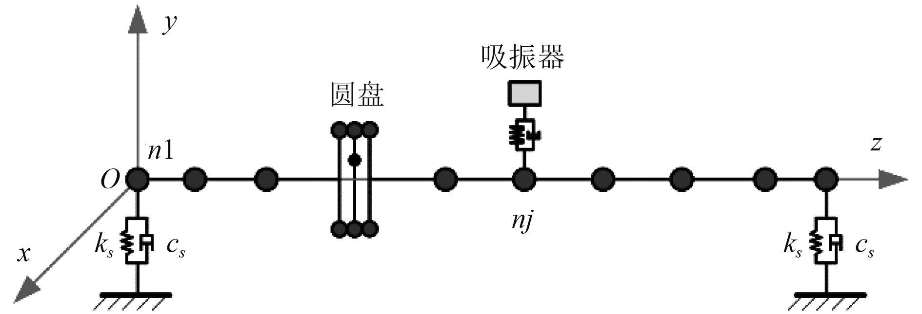
1 吸振器-转子耦合系统的动力学建模将某船用燃气轮机转子系统简化为圆盘偏置的具有对称支承的单跨单盘单转子结构,利用有限元法将转子系统离散为具有N个节点的多自由度系统,将转子吸振器(Vogit式)安装在节点nj处,系统简图如图1所示。
|
图 1 系统简图 Fig. 1 System simplified diagram |
对系统进行离散后进一步依据拉格朗日方程建立吸振器-转子耦合系统的动力学方程如下[16]:
| $ {{{\boldsymbol{M}}\ddot {\boldsymbol{x}}}} + {{{\boldsymbol{C}}\dot {\boldsymbol{x}}}} + {{{\boldsymbol{Kx}}}} = {{{\boldsymbol{F}}}}(t)。$ | (1) |
式中:
| $\begin{aligned} {\boldsymbol{M}} = \left[ \begin{gathered} {{\boldsymbol{M}}_{{p}}} {\boldsymbol{0}} \\ {\boldsymbol{0}} {m_{{a}}} \\ \end{gathered} \right] \text{,} {\boldsymbol{C}} = \left[ \begin{gathered} {{\boldsymbol{C}}_{{p}}} + {{\boldsymbol{C}}_{{{a1}}}} {{\boldsymbol{C}}_{{{pa}}}} \\ {\boldsymbol{C}}_{{{pa}}}^{\text{T}} {c_{{a}}} \\ \end{gathered} \right] \text{,} \\ {\boldsymbol{K}} = \left[ \begin{gathered} {{\boldsymbol{K}}_{{p}}} + {{\boldsymbol{K}}_{{{a1}}}} {{\boldsymbol{K}}_{{{pa}}}} \\ {\boldsymbol{K}}_{{{pa}}}^{\text{T}} {k_{{a}}} \\ \end{gathered} \right] \text{,} {\boldsymbol{F}}(t) = \left[ \begin{gathered} {{\boldsymbol{F}}_{{p}}}(t) \\ 0 \\ \end{gathered} \right] 。\end{aligned}$ |
其中,Mp,Cp,Kp为转子系统的质量、阻尼、刚度矩阵;ma,ca,ka为吸振器的质量、阻尼和刚度;Ca1和Ka1分别为与Cp和Kp等维零矩阵的第j行第j列加上ca和ka后生成的矩阵;Cpa和Kpa分别为动力吸振器与转子系统的阻尼交叉项、刚度交叉项。
| $ {{{{\boldsymbol{C}}}}_{{{ca}}}} = {\left[ {\underbrace {0 \cdots 0}_{{{j - 1}}}{\kern 1pt} {\kern 1pt} {\kern 1pt} {\kern 1pt} {\kern 1pt} {\kern 1pt} - {c_{\text{a}}}{\kern 1pt} {\kern 1pt} {\kern 1pt} {\kern 1pt} 0 \cdots 0} \right]^{\text{T}}} \text{,} {{{{\boldsymbol{K}}}}_{{{ca}}}} = {\left[ {\underbrace {0 \cdots 0}_{{{j - 1}}}{\kern 1pt} {\kern 1pt} {\kern 1pt} {\kern 1pt} {\kern 1pt} {\kern 1pt} - {k_{{a}}}{\kern 1pt} {\kern 1pt} {\kern 1pt} {\kern 1pt} 0 \cdots 0} \right]^{\text{T}}} 。$ |
将转子系统简称为主系统,转子吸振器简称为DVA(dynamic vibration absorber),组合系统简称耦合系统。
2 仿真分析 2.1 主系统的仿真参数及模态分析将主系统离散为9个轴段,10个节点,具体轴段参数如表1所示。节点n5处为圆盘的中心位置,存在质量偏心,质量偏心距me=7.9×10⁻⁵ kg∙m,节点n1和n10处具有对称支承,支承刚度ks=1×10⁸ N/m,支承阻尼为cs=7×105 N∙s/m。
|
|
表 1 轴段参数 Tab.1 Parameters of shaft |
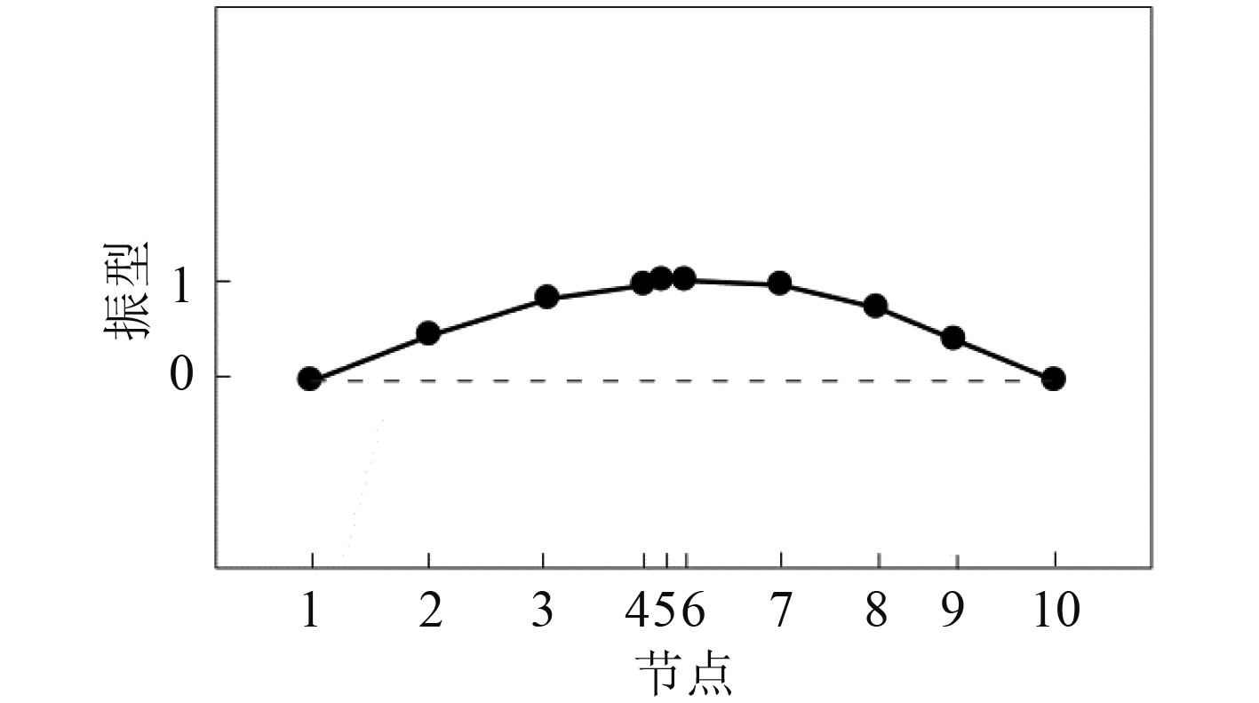
对转子系统进行模态分析后得知转子y向的一阶临界转速ωp=330.997 rad/s (52.68 Hz),一阶模态质量mp=1.073 kg,一阶模态振型如图2所示。观察振型图可知,发生一阶共振时,主系统节点n5处具有最大振幅。因此,假设该节点的y向有碰摩风险,需安装转子吸振器进行振动抑制。
|
图 2 主系统的一阶振型图 Fig. 2 First mode shape chart of main system |
使用文献[15]内的优化方法及策略:利用限边界的坐标轮换法在0.5≤λ≤1.5,0≤γa≤2,0≤ζa≤1范围内寻找{γaopt, ζaopt}满足于min(max(β(λ,γa,ζa)))。其中,λ=ω/ωp称为转速比,是转速与主系统一阶临界转速ωp之比;γa=ωa/ωp称为频率比,是吸振器的固有频率ωa与主系统一阶临界转速ωp之比,γaopt为最优频率比;ζa=ca/(2(maka)−2)为DVA的阻尼比,ζaopt为最优阻尼比;β为放大率,是安装DVA后主系统一阶共振峰值与未安装时共振峰值之比。
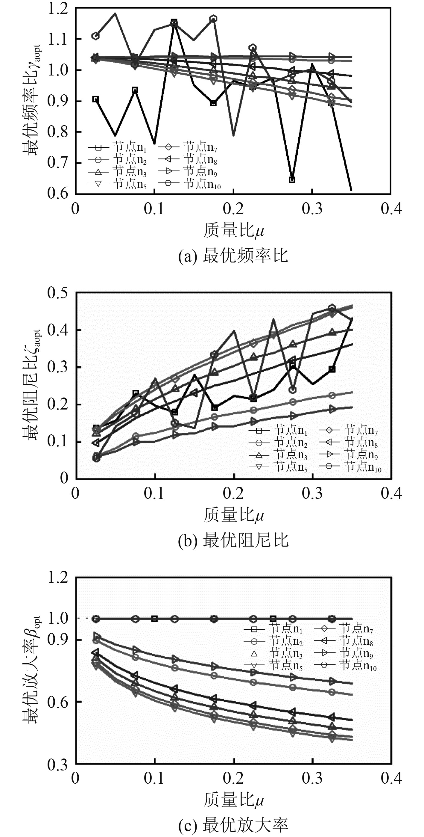
2.3 优化分析 2.3.1 不同安装位置的吸振器参数优化对分别安装在各节点的质量比μ(μ=ma/mp)在0.025~0.35范围内的吸振器进行参数优化(由于n4、n5、n6的位置非常接近,所以不考虑n4、n6两点),寻优结果如图3所示。由图3(c)可知,安装在节点n1和n10两个支承位置的吸振器的最优放大率约等于1,表明这2个位置的吸振器基本不具备吸振效果;任意质量比下安装在n5的吸振器具有最小的最优放大率(μ=0.025时βopt=0.78;μ=0.35时βopt=0.42),表明该点的吸振器具有最优的抑振性能。各质量比下,按照抑振效果由优到差排列顺序基本为n5,n7,n3,n8,n2,n1(n10)。由图3(a)及图3(b)可知,安装在n5的吸振器具有更小的频率比和更大的阻尼比。
|
图 3 安装在不同节点的各质量比的最优DVA的参数及最优放大率 Fig. 3 Optimal magnification and optimal DVA parameters with different nodes and different mass ratios |
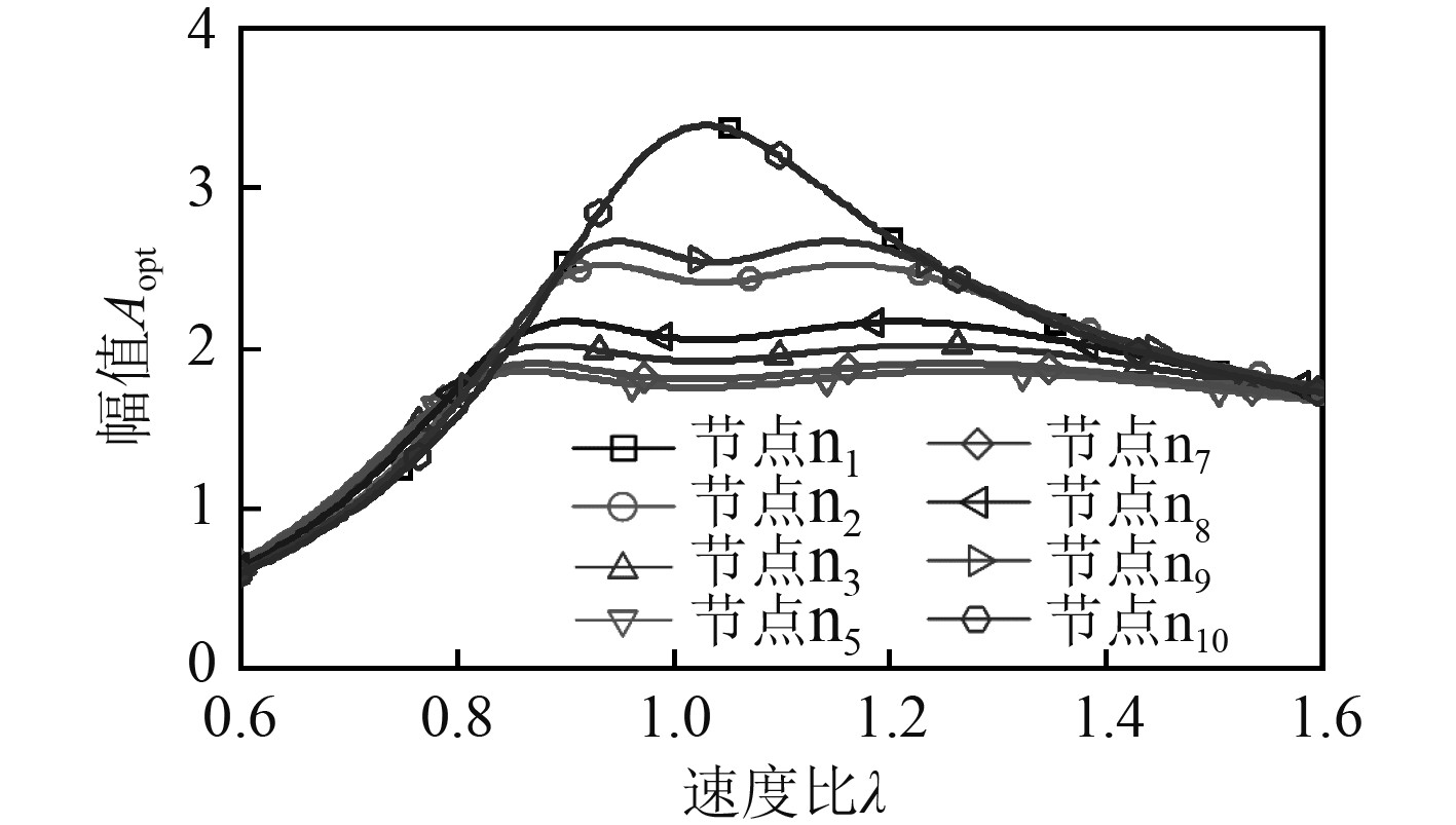
图4为各节点安装μ=0.15最优DVA时节点n5处的频响曲线。可以看出,除n1和n10之外的其余各点,具有碰摩风险的共振区范围内,在n5安装吸振器时主系统的幅值小于其他安装位置。
|
图 4 安装μ=0.15最优DVA时主系统的频响曲线 Fig. 4 Frequency response curves of main system at different nodes when the μ of the optimal DVA is 0.15 |
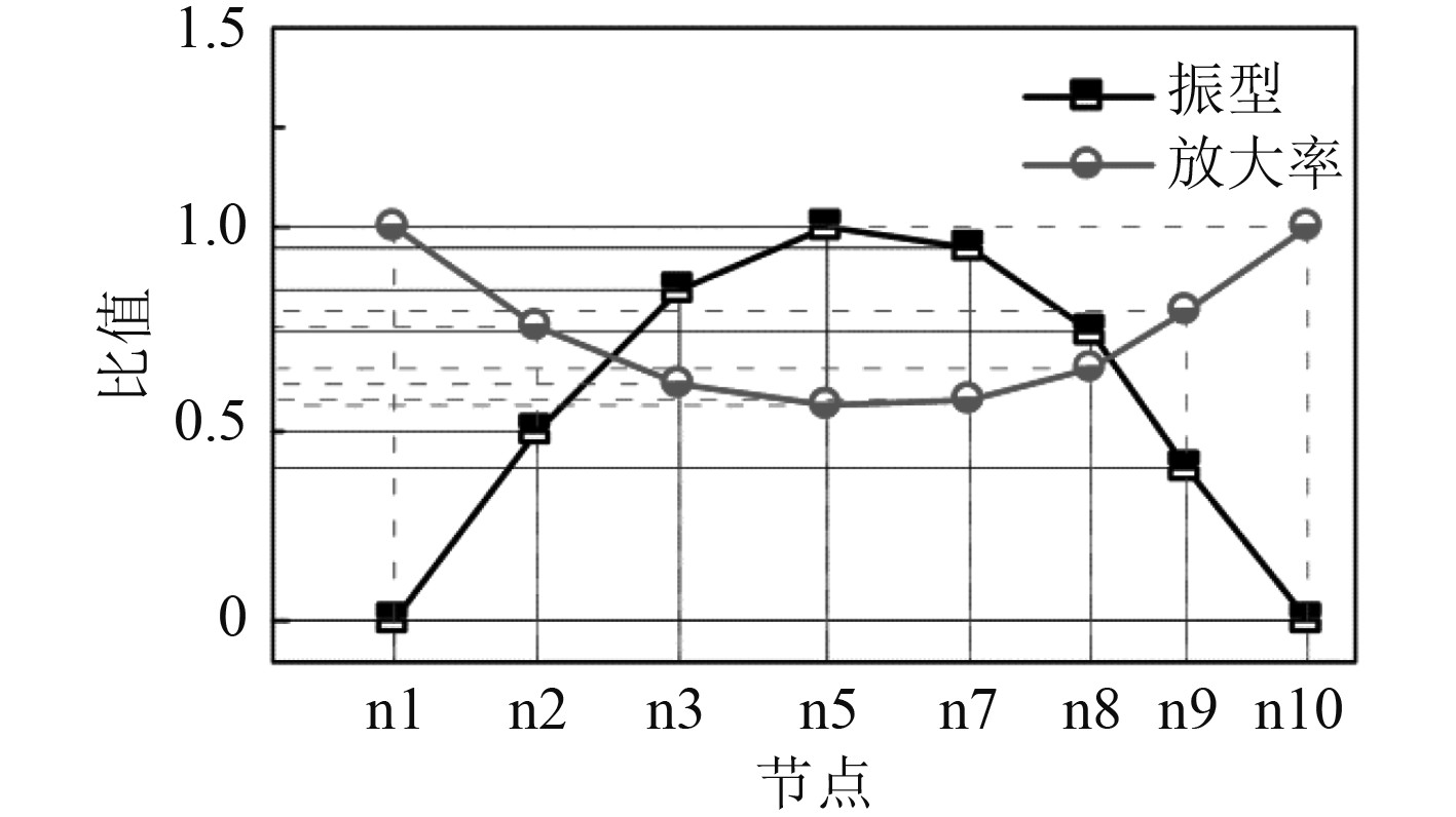
将未安装DVA时主系统的一阶振型与在各节点安装μ=0.15最优DVA的放大率进行对比,结果如图5所示。可知,DVA的放大率与节点振幅大小呈负相关,安装节点的振幅越大,放大率越小,抑制性能越优。
|
图 5 最优DVA的放大率与各节点振幅的对照关系 Fig. 5 The relationship between magnification of the optimal DVA and the amplitude of each node |
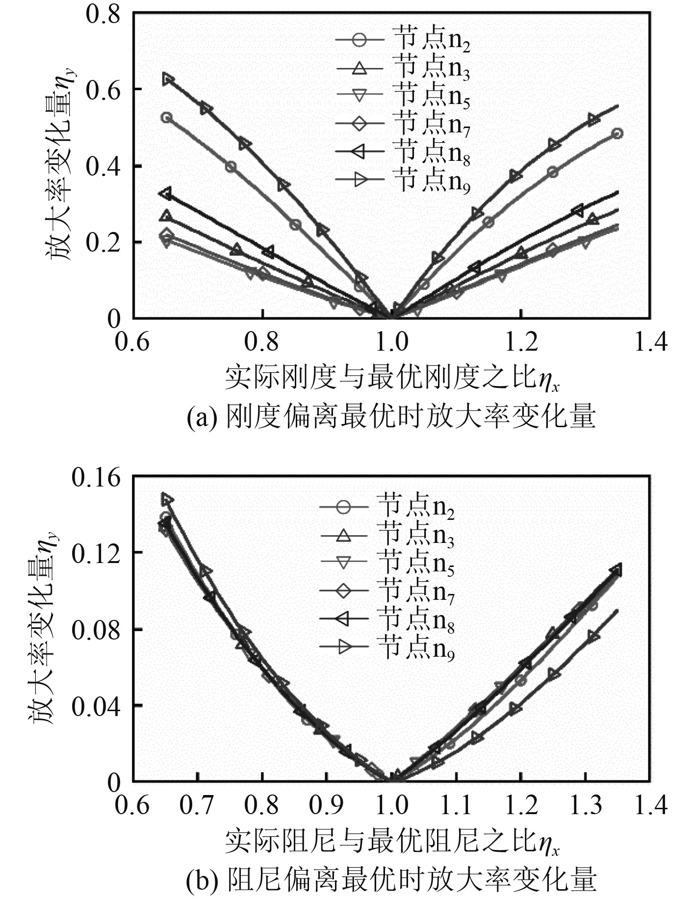
假设DVA参数因设计误差、疲劳等问题偏离了最优值,偏离范围在0.65~1.35。对安装在各节点的μ=0.15最优DVA对参数最优偏离的敏感性进行分析(由于n1和n10两点的DVA抑振效果太差,此处不作分析),结果如图6所示。由图6(a)可以看出,刚度偏离最优时,安装在n5的DVA放大率的变化量最大仅为ηy=0.24(ηy=(刚度最优偏离后的放大率-βopt)/(1-βopt)),该值远小于其他安装位置DVA放大率的变化量,这表明在振幅最大位置安装的DVA最优抑振性能对刚度偏离的敏感性最迟钝。由图6(b)可以看出,阻尼偏离最优时,安装在各节点的DVA放大率变化量大致相同,最大仅为0.15左右。
|
图 6 不同安装节点最优DVA参数最优偏离的敏感性 Fig. 6 Optimal deviation sensitivity of optimal DVA parameters at different installation nodes |
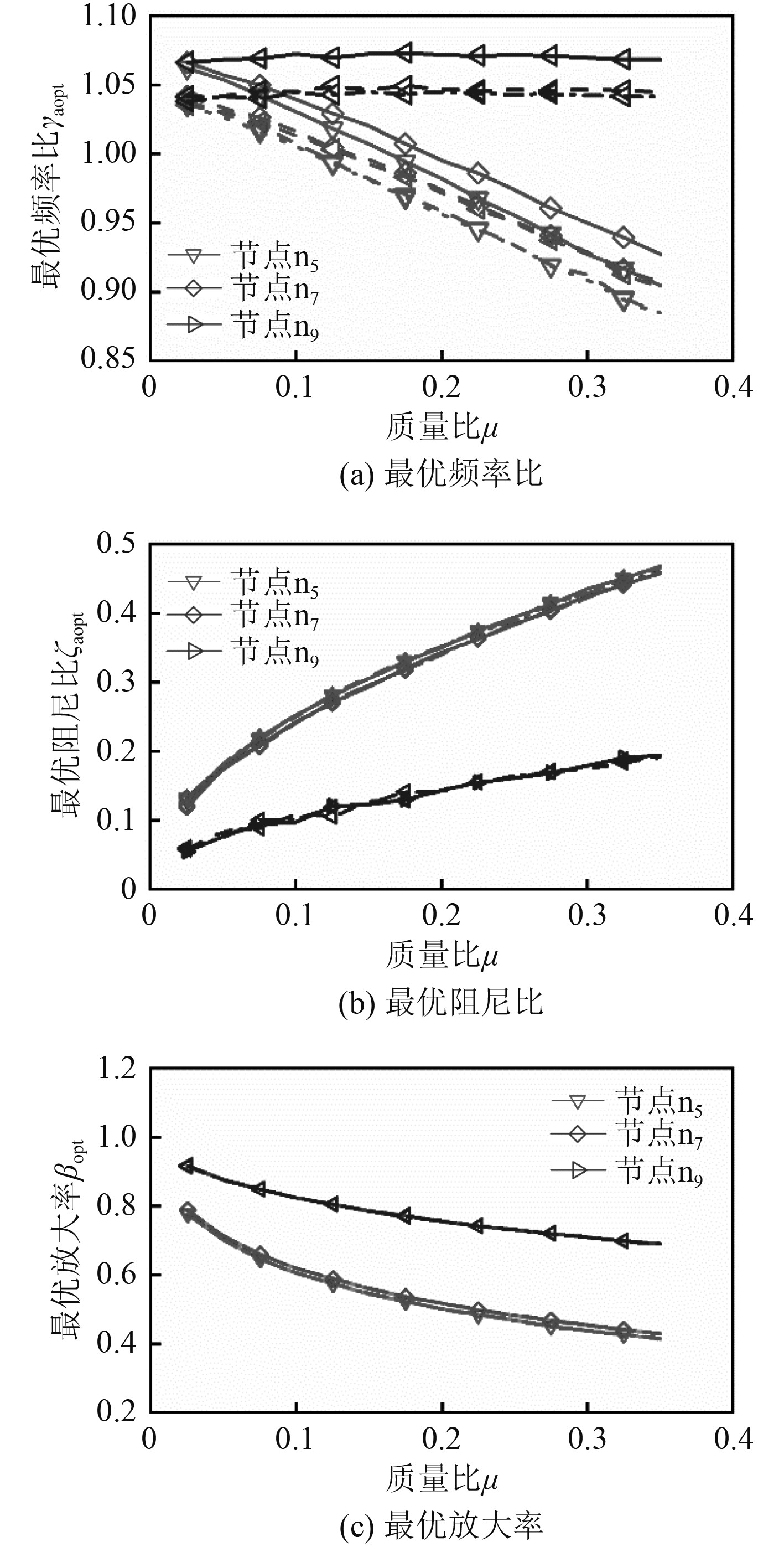
由于支承刚度可以影响主系统的一阶临界转速,所以探究支承刚度与DVA的最优安装位置的关系。对支承刚度分别为1×10⁶N/m(点划线所示),1×107 N/m(虚线所示),1×108 N/m(实线所示),安装在节点n5,n7,n9的DVA进行参数优化,结果如图7所示。由图7(a)可知,支承刚度越大,各安装位置的最优频率比更大,即所需DVA刚度越大。不同支承刚度时,各个安装位置的DVA的最优阻尼比和最优放大率曲线基本重合,差值不及0.1%,表明支承刚度对二者的影响甚微。
|
图 7 支承刚度变化时,设置在节点n5,n7,n9的最优DVA的参数及最优放大率 Fig. 7 Optimal magnification and optimal DVA parameters at node n5, n7and n9 when the supporting stiffness changes |
对船用燃气轮机转子吸振器的抑振性能与安装位置的关系进行了分析,结果如下:
1) 安装在转子系统各节点的最优吸振器抑振性能与各节点的振幅大小相关,未安装吸振器时振幅越大的节点其抑振性能越优异。当目标抑振位置不能安装吸振器时,应尽量将吸振器安装在除该点外振幅最大的位置。
2) 振幅最大节点的最优吸振器对参数最优偏离的敏感性最迟钝,该安装位置的吸振器抑振性能最具稳定性。
3)转子系统的支承刚度越大,吸振器的最优频率比越大,所需吸振器刚度越大,而支承刚度对最优阻尼比及振幅放大率的影响甚微。
| [1] |
闻雪友, 任兰学, 祁龙, 等. 舰船燃气轮机发展现状、方向及关键技术[J]. 推进技术, 2020, 41(11): 2401-2407. WEN X Y, REN L X, QI L, et al. Development and key technologies in marine gas turbine[J]. Journal of Propulsion technology, 2020, 41(11): 2401-2407. |
| [2] |
李立波, 雒兴刚, 张修寰, 等. 9FA重型燃气轮机转子高速动平衡研究[J]. 燃气轮机技术, 2011, 24(4): 9-11. LI L B, LUO X G, ZHANG X H, et al. High speed dynamic balancing of 9FA gas turbine rotor[J]. Gas Turbine Technology, 2011, 24(4): 9-11. |
| [3] |
解梦涛, 张强波, 张霞妹. 基于全相位FFT不平衡分析的转子现场动平衡[J]. 振动. 测试与诊断, 2021, 41(3): 566–570. XIE M T, ZHANG Q B, ZHANG X M, et al. Strong seismic damage cracking of pumping station outlet tower[J]. Journal of Vibration, Measurement & Diagnosis, 2021, 41(3): 566–570. |
| [4] |
XIANG B, WEN T, LIU Z. Vibration analysis, measurement and balancing of flywheel rotor suspended by active magnetic bearing[J]. Measurement, 2022, 197: 111305.
|
| [5] |
YU X, MAO K, LEI S, et al. A new adaptive proportional-integral control strategy for rotor active balancing systems during acceleration[J]. Mechanism and Machine Theory, 2019, 136: 105–121.
|
| [6] |
MA Y, ZHANG Q, ZHANG D, et al. Tuning the vibration of a rotor with shape memory alloy metal rubber supports[J]. Journal of Sound and Vibration, 2015, 351: 1–16.
|
| [7] |
PAN W, LI X, LING L, et al. Dynamic modeling and response analysis of rub-impact rotor system with squeeze film damper under maneuvering load[J]. Applied Mathematical Modelling, 2023, 114: 544–582.
|
| [8] |
MA X, MA H, QIN H, et al. Nonlinear vibration response characteristics of a dual-rotor-bearing system with squeeze film damper[J]. Chinese Journal of Aeronautics, 2021, 34(10): 128–147.
|
| [9] |
冯浩然, 何立东, 夏雪然, 等. 四跨转子应用调谐质量吸振器抑制临界转速振动实验研究[J]. 北京化工大学学报(自然科学版), 2017, 44(4): 76–81. FENG H R, HE L D, XIA X R, et al. Experimental study of the critical speed vibration control for four-span rotors with tuned mass absorbers[J]. Journal of Beijing University of Chemical Technology (Natural Science), 2017, 44(4): 76–81. |
| [10] |
TAGHIPOUR J, DARDEL M, PASHAEI M H. Vibration mitigation of a nonlinear rotor system with linear and nonlinear vibration absorbers[J]. Mechanism and Machine Theory, 2018, 128: 586–615.
|
| [11] |
TEHRANI G G, DARDEL M. Vibration mitigation of a flexible bladed rotor dynamic system with passive dynamic absorbers[J]. Communications in Nonlinear Science and Numerical Simulation, 2019, 69: 1–30.
|
| [12] |
曹焱博, 李之傲, 韩金超, 等. 非光滑NES在转子-叶片系统振动抑制中的应用[J]. 东北大学学报(自然科学版), 2020, 41(8): 1103–1110. CAO Y B, LI Z A, HAN J C, et al. Application of non - smooth NES in vibration suppression of rotor - blade systems [J]. Journal of Northeastern University( Natural Science), 2020, 41(8): 1103–1110. |
| [13] |
BAB S, NAJAFI M, FATHI SOLA J, et al. Annihilation of non-stationary vibration of a gas turbine rotor system under rub-impact effect using a nonlinear absorber[J]. Mechanism and Machine Theory, 2019, 139: 379–406.
|
| [14] |
DOU J, YAO H, CAO Y, et al. Permanent magnet based nonlinear energy sink for torsional vibration suppression of rotor systems[J]. International Journal of Non-Linear Mechanics, 2023, 149: 104321.
|
| [15] |
刘子良, 许琦, 李文龙, 等. 一种转子动力吸振器的参数优化方法[J]. 航空动力学报, 2018, 33(10): 2359–2366. LIU Z L, XU Q, LI W L, et al. Parameter optimization method of rotor dynamic vibration absorber[J]. Journal of Aerospace Power, 2018, 33(10): 2359–2366. |
| [16] |
LIU Z L, ZHANG Q, CAO Y B, et al. Parameter optimization design of rotor dynamic vibration absorber[J]. Journal of Vibroengineering, 2019, 21(2): 301–317.
|
 2023, Vol. 45

