2. 中国船舶科学研究中心,江苏 无锡 214082
2. China Ship Scientific Research Center, Wuxi 214082, China
深潜救生艇是一种可与沉没失事潜艇对接,援救出被困幸存艇员的载人潜水器,是执行潜艇救生保障的核心防救装备[1-3]。受到海洋环境、失事潜艇坐沉海底姿态等影响,深潜救生艇作业是一项与操纵人员技能密切相关的复杂人因工程,而深潜救生艇模拟器是目前有效提高操纵人员实操技能的主要手段之一[4]。
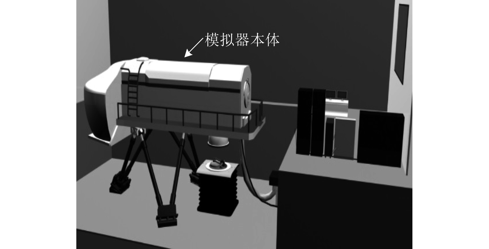
深潜救生艇模拟器主要由本体、六自由度平台系统、视景系统、对接系统和教控系统等组成,其中本体分为指挥舱和救生舱,如图1所示。指挥舱是人员操纵深潜救生艇模拟器的部位,因此舱内布置有与实装一致的各种仪器设备和控制面板,由24 V电压供电[5-6]。
|
图 1 深潜救生艇模拟器 Fig. 1 The simulator of SRV |
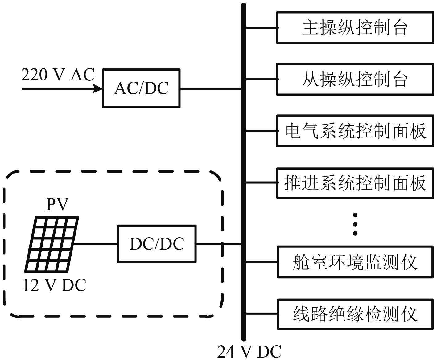
为了提高深潜救生艇模拟器系统鲁棒性,同时降低能耗,系统24 V电源采用“电网+光伏”双回路供电模式,2种供电排布方式为并联结构,其中光伏供电模块由DC/DC变换器将直流12 V电压变换为直流24 V,以提供给24 V配电网路,进而送入并网至指挥舱,向舱内供电,如图2所示。
|
图 2 深潜救生艇模拟器24 V电源结构 Fig. 2 The 24 V power supply structure of SRV simulator |
受到工作环境、功能任务等要求,深潜救生艇模拟器指挥舱仪器设备和控制面板对电磁干扰敏感,但目前深潜救生艇模拟器光伏供电模块高电磁干扰(包括较弱的抗干扰能力和较强的干扰其他设备能力)问题突出,严重影响了模拟器性能发挥。
为满足深潜救生艇模拟器对24 V电源低电磁干扰特性的需求,本文针对现有变换器技术缺点,提出一种输入电流零纹波、输出电流低纹波的新型DC-DC变换器,以作为深潜救生艇模拟器24 V电源的电路,从而有效降低外界传导干扰对24 V电源的影响,保证24 V电源工作时对指挥舱内设备和面板的低干扰,以提高模拟器性能。
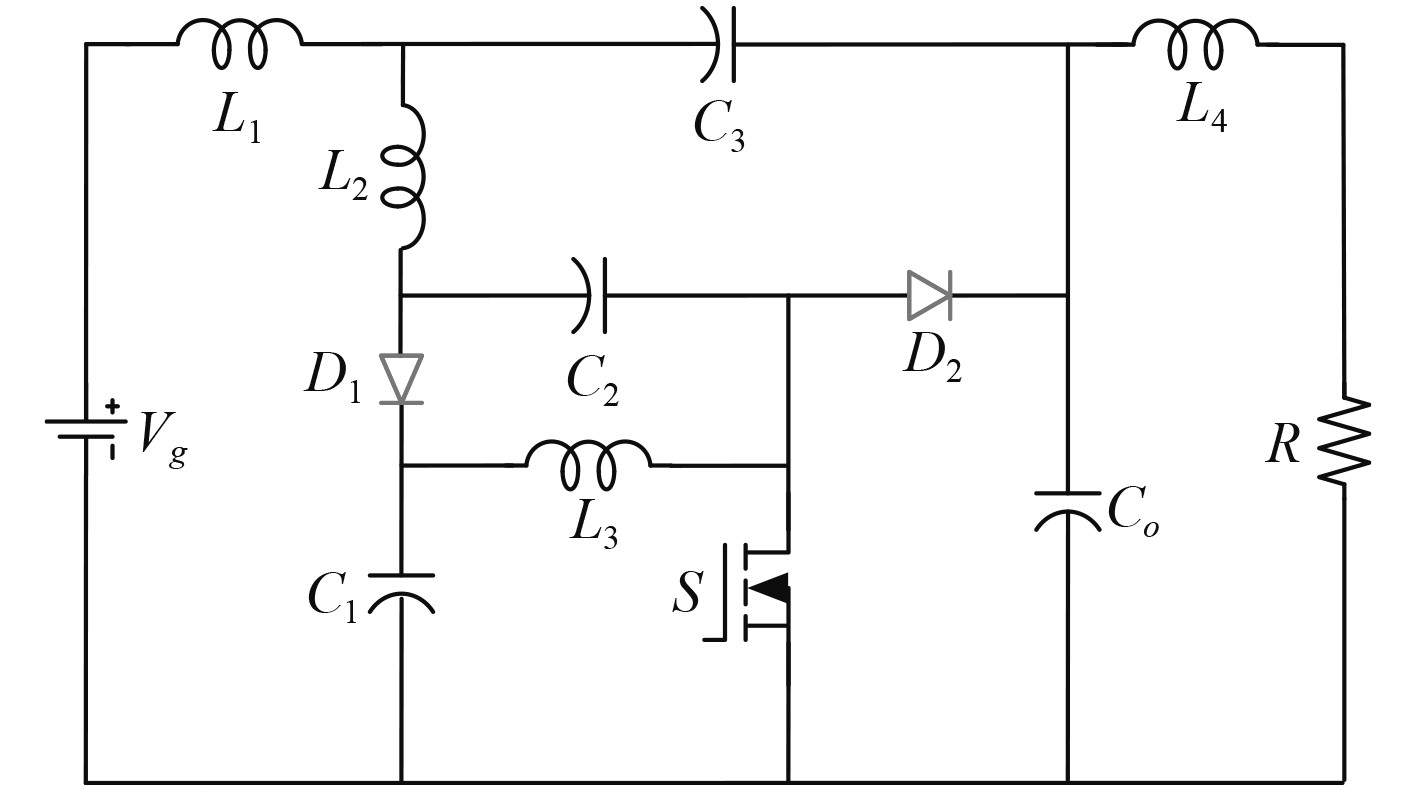
1 工作模式本文提出的深潜救生艇模拟器24 V电源新型变换器为零输入电流纹波单开关管直流变换器,变换器由1个功率开关管(S)、4个电容器(Co,C1,C2,C3)、2个二极管(D1,D2)、4个电感(L1,L2,L3,L4)和负载组成,如图3所示。
|
图 3 变换器结构原理图 Fig. 3 The schematic diagram of converter |
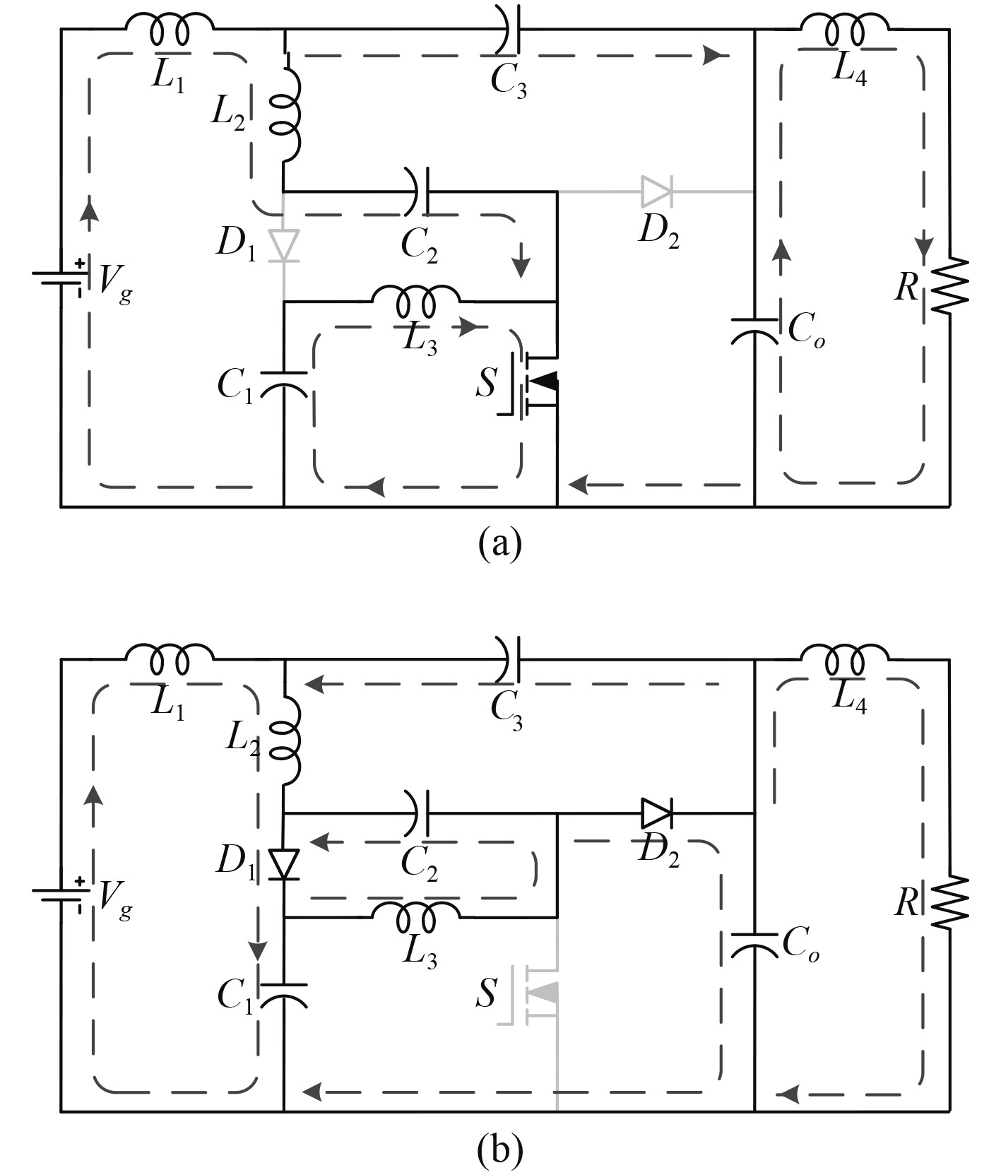
深潜救生艇模拟器24 V电源新型变换器在CCM工作模式下的工作状态包括2种,如图4所示。2种状态具体如下:
|
图 4 变换器工作状态 Fig. 4 The working states of converter |
状态1 [t0, t1](见图4(a)):此状态为传统直通状态,在此状态下,开关管S导通,二极管 D1和D2截止,D1和D2分别被VC1+VC2和VCo反向偏置。输入电压Vg 及电容C1,C2,C3,Co 共同放电将能量传输到负载侧,当开关管S两端电压降为0时,该状态结束。
状态2 [t1, t2](见图4(b)):开关管S关断,二极管D1和D2导通,开关管S被VC1+VC2反向偏置。此时输入电压Vg 为电容C1,C2,C3,Co 充电,当电容C1,C2,C3,Co充电结束,二极管D1和D2的电流降为0时,此状态结束。
2 直流稳态分析为简化深潜救生艇模拟器24 V电源新型变换器电路分析,假设变换器电容、电感、二极管和功率管等均为理想情况;4个电感L1,L2,L3,L4容值相同且流过电流连续;4个电容C1,C2,C3,Co 相同且电容容值足够大。
变换器电路工作在D<0.5情况下,在一个工作周期内工作过程为工作模式1~2,每个阶段的时间分别为Dts,(1-D)ts。
变换器按照开关频率周期工作,在第一个工作过程中,变换器工作于工作模式1下,进行直流稳态分析得到电压和电流关系分别有:
| $ \left\{ \begin{gathered} {V_{{\text{L1\_ON}}}} = {V_{\text{g}}} - {V_{{\text{CO}}}} + {V_{{\text{C3}}}} ,\\ {V_{{\text{L2\_ON}}}} = {V_{{\text{C2}}}} + {V_{{\text{CO}}}} - {V_{{\text{C3}}}} ,\\ {V_{{\text{L3\_ON}}}} = {V_{{\text{C1}}}},\\ {V_{{\text{L4\_ON}}}} = {V_{{\text{CO}}}} - {V_{\text{o}}}。\\ \end{gathered} \right. $ | (1) |
| $ \left\{ \begin{gathered} {I_{{\text{C1\_ON}}}} = - {I_{{\text{L1}}}},\\ {I_{{\text{C2\_ON}}}} = - {I_{{\text{L2}}}},\\ {I_{{\text{C3\_ON}}}} = {I_{{\text{L2}}}} - {I_{{\text{L1}}}} ,\\ {I_{{\text{Co\_ON}}}} = - {I_{{\text{L1}}}} - {I_{{\text{L2}}}} - {I_{{\text{L4}}}} 。\\ \end{gathered} \right. $ | (2) |
在工作模式1下:VL1_ON,VL2_ON,VL3_ON,VL4_ON分别为电感L1,L2,L3,L4两端电压;IL1,IL2,IL3,IL4为流过电感L1,L2,L3,L4的电流;IC1_ON,IC2_ON,IC3_ON,IC4_ON为流过电容C1,C2,C3,Co的电流。
在第2个工作过程中,变换器工作于工作模式2下,进行直流稳态分析得到电压和电流关系分别有:
| $ \left\{ \begin{gathered} {V_{{\text{L1\_OFF}}}} = {V_{\text{g}}} - {V_{{\text{CO}}}} + {V_{{\text{C3}}}} ,\\ {V_{{\text{L2\_OFF}}}} = {V_{{\text{C2}}}} - {V_{{\text{C3}}}},\\ {V_{{\text{L3\_OFF}}}} = - {V_{{\text{C2}}}} ,\\ {V_{{\text{L4\_OFF}}}} = {V_{{\text{CO}}}} - {V_{\text{o}}}。\\ \end{gathered} \right. $ | (3) |
| $ \left\{ \begin{gathered} {I_{{\text{C1\_OFF}}}} = {I_{{\text{D1}}}} - {I_{{\text{L3}}}},\\ {I_{{\text{C2\_OFF}}}} = {I_{{\text{D1}}}} - {I_{{\text{L2}}}},\\ {I_{{\text{C3\_OFF}}}} = {I_{{\text{L2}}}} - {I_{{\text{L1}}}},\\ {I_{{\text{Co\_OFF}}}} = {I_{{\text{D2}}}} - {I_{{\text{C3\_OFF}}}} - {I_{{\text{L4}}}} 。\\ \end{gathered} \right. $ | (4) |
在工作模式2下:VS为开关管两端电压;VL1_OFF,VL2_OFF,VL3_OFF,VL4_OFF分别为电感L1,L2,L3,L4两端电压;IL1,IL2,IL3,IL4为流过电感L1,L2,L3,L4的电流;IC1_OFF,IC2_OFF,IC3_OFF,IC4_OFF为流过电容C1,C2,C3,Co的电流;ID1,ID2为流过二极管D1,D2的电流。
电路工作在稳态且理想情况下,根据电感的伏秒平衡法则:
| $ \left\{ \begin{gathered} \int_0^{DT} {{V_{{\text{L1\_ON}}}}{\rm{d}}t + \int_{DT}^T {{V_{{\text{L1\_OFF}}}}{\rm{d}}t} = 0} ,\\ \int_0^{DT} {{V_{{\text{L2\_ON}}}}{\rm{d}}t + \int_{DT}^T {{V_{{\text{L2\_OFF}}}}{\rm{d}}t} = 0} ,\\ \int_0^{DT} {{V_{{\text{L3\_ON}}}}{\rm{d}}t + \int_{DT}^T {{V_{{\text{L3\_OFF}}}}{\rm{d}}t} = 0} ,\\ \int_0^{DT} {{V_{{\text{L4\_ON}}}}{\rm{d}}t + \int_{DT}^T {{V_{{\text{L4\_OFF}}}}{\rm{d}}t} = 0} 。\\ \end{gathered} \right. $ | (5) |
可得:
| $ \left\{ \begin{gathered} {V_{{\text{C1}}}} = \frac{{1 - D}}{{1 - 2D}}{V_{\text{g}}} = (1 - D){V_{\text{o}}} ,\\ {V_{{\text{C2}}}} = \frac{D}{{1 - 2D}}{V_{\text{g}}} = D{V_{\text{o}}},\\ {V_{{\text{C3}}}} = \frac{{2D}}{{1 - 2D}}{V_{\text{g}}} = 2D{V_{\text{o}}} ,\\ {V_{{\text{Co}}}} = \frac{1}{{1 - 2D}}{V_{\text{g}}} 。\\ \end{gathered} \right. $ | (6) |
又由:
| $ \left\{ \begin{gathered} {V_{\text{S}}} = {V_{{\text{CO}}}},\\ {V_{{\text{D1}}}} = {V_{{\text{C1}}}} + {V_{{\text{C2}}}} ,\\ {V_{{\text{D2}}}} = {V_{{\text{CO}}}}。\\ \end{gathered} \right. $ | (7) |
可得:
| $ \left\{ \begin{gathered} {V_{\text{S}}} = \frac{1}{{1 - 2D}}{V_{\text{g}}} = {V_{\text{o}}},\\ {V_{{\text{D1}}}} = \frac{1}{{1 - 2D}}{V_{\text{g}}} = {V_{\text{o}}},\\ {V_{{\text{D2}}}} = \frac{1}{{1 - 2D}}{V_{\text{g}}} = {V_{\text{o}}}。\\ \end{gathered} \right. $ | (8) |
进而得到:
| $ \left\{ \begin{gathered} {V_{{\rm{L1\_ON}}}} = 0 ,\\ {V_{{\rm{L1\_OFF}}}} = 0 ,\\ {V_{{\rm{L2\_ON}}}} = \frac{{(1 - D)}}{{1 - 2D}}{V_{\text{g}}} = (1 - D){V_{\text{o}}} ,\\ {V_{{\rm{L2\_OFF}}}} = \frac{D}{{1 - 2D}}{V_{\text{g}}} = D{V_{\text{o}}},\\ {V_{{\rm{L3\_ON}}}} = \frac{{(1 - D)}}{{1 - 2D}}{V_{\text{g}}} = (1 - D){V_{\text{o}}} ,\\ {V_{{\rm{L3\_OFF}}}} = \frac{D}{{1 - 2D}}{V_{\text{g}}} = D{V_{\text{o}}},\\ {V_{{\rm{L4\_ON}}}} = 0 ,\\ {V_{{\rm{L4\_OFF}}}} = 0 。\\ \end{gathered} \right. $ | (9) |
综上可得深潜救生艇模拟器24 V电源新型变换器的输入输出关系为:
| $ {V_{{\text{Co}}}} = \frac{1}{{1 - 2D}}{V_{\text{g}}} 。$ | (10) |
根据深潜救生艇模拟器24 V电源新型变换器工作原理中电压增益的推导过程,可得电容电压应力为:
| $ {V_{{\text{C1}}}} = (1 - D){V_{\text{o}}} ,$ | (11) |
| $ {V_{{\text{C2}}}} = D{V_{\text{o}}} ,$ | (12) |
| $ {V_{{\text{C3}}}} = 2D{V_{\text{o}}} ,$ | (13) |
| $ {V_{{\text{Co}}}} = {V_{\text{o}}} 。$ | (14) |
开关管和二极管的电压应力为:
| $ {V_{\text{S}}} = {V_{{\text{D1}}}} = {V_{{\text{D2}}}} = {V_{\text{o}}} 。$ | (15) |
根据基尔霍夫电流定律可得:
| $ \left\{ \begin{gathered} {I_{{\rm{C1\_ON}}}} = - {I_{{\text{L1}}}} ,\\ {I_{{\rm{C2\_ON}}}} = - {I_{{\text{L2}}}} ,\\ {I_{{\rm{C3\_ON}}}} = {I_{{\text{L2}}}} - {I_{{\text{L1}}}},\\ {I_{{\rm{Co\_ON}}}} = - {I_{{\text{L1}}}} - {I_{{\text{L2}}}} - {I_{{\text{L4}}}} 。\\ \end{gathered} \right. $ | (16) |
| $ \left\{ \begin{gathered} {I_{{\rm{C1\_OFF}}}} = {I_{{\text{D1}}}} - {I_{{\text{L3}}}} ,\\ {I_{{\rm{C2\_OFF}}}} = {I_{{\text{D1}}}} - {I_{{\text{L2}}}} ,\\ {I_{{\rm{C3\_OFF}}}} = {I_{{\text{L2}}}} - {I_{{\text{L1}}}} ,\\ {I_{{\rm{Co\_OFF}}}} = {I_{{\text{D2}}}} - {I_{{\rm{C3\_OFF}}}} - {I_{{\text{L4}}}} 。\\ \end{gathered} \right. $ | (17) |
由功率守恒可得:
| $ D{I_{\text{S}}} + (1 - D){I_{{\text{D2}}}} - B{I_{\text{o}}} = 0,$ | (18) |
根据稳态条件下电容的安秒平衡:
| $ \int_0^{DT} {{i_{{\text{Ci\_ON}}}}} {\rm{d}}t + \int_{DT}^T {{i_{{\text{Ci\_OFF}}}}} {\rm{d}}t = 0{\text{ }}(i = 1,2,3,{\text{o}}) $ | (19) |
可得开关管、二极管和电感电流应力为:
| $ {I_{\text{S}}} = \frac{2}{{1 - 2D}}{I_{\text{o}}} ,$ | (20) |
| $ \left\{ \begin{gathered} {I_{{\text{D1}}}} = \frac{1}{{1 - 3D + 2{D^{\text{2}}}}}{I_{\text{o}}} ,\\ {I_{{\text{D2}}}} = \frac{1}{{1 - D}}{I_{\text{o}}} 。\\ \end{gathered} \right. $ | (21) |
| $ \left\{ \begin{gathered} {I_{{\text{L1}}}} = \frac{1}{{1 - 2D}}{I_{\text{o}}} ,\\ {I_{{\text{L2}}}} = \frac{1}{{1 - 2D}}{I_{\text{o}}} ,\\ {I_{{\text{L3}}}} = \frac{1}{{1 - 2D}}{I_{\text{o}}} ,\\ {I_{{\text{L4}}}} = {I_{\text{o}}} 。\\ \end{gathered} \right. $ | (22) |
将变换器中主要器件的电压和电流应力进行总结,如表1所示。
|
|
表 1 变换器主要器件电压和电流应力 Tab.1 Voltage and current stress of converter’s main devices |
深潜救生艇模拟器24 V电源新型变换器功耗包括开关管损耗、二极管损耗、耦合绕组损耗和电容损耗。变换器带寄生参数的等效电路如图5所示。为了计算变换器的导通损耗和开关损耗,将所有二极管的正向压降和等效导通电阻定义为VFD和rD;开关管的等效导通电阻定义为rS;耦合绕组的寄生电阻分别为rL1,rL2,rL3,rL4;电容C1,C2,C3,Co的寄生电阻分别为rC1,rC2,rC3,rCo。

|
图 5 带寄生参数等效电路图 Fig. 5 Equivalent circuit diagram with parasitic parameters |
开关管损耗包括导通损耗和开关损耗,其导通损耗为:
| $ \begin{split} {P}_{\text{cond,S}}=\frac{1}{T}{\displaystyle {\int }_{0}^{T}{r}_{\text{S}}{i}_{\text{S}}^{2}}{\rm{d}}t={r}_{\text{S}}{I}_{\rm{S\_rms}}^{2},\end{split} $ | (23) |
开关管的开关损耗为:
| $ \begin{split} {P}_{\text{SW,S}}=&\frac{1}{T}\left({\displaystyle {\int }_{0}^{{t}_{\text{on}}}{V}_{\text{S}}{i}_{\text{S}}}{\rm{d}}t+{\displaystyle {\int }_{0}^{{t}_{\text{off}}}{V}_{\text{S}}{i}_{\text{S}}}{\rm{d}}t\right)=\\ & \frac{1}{6}{V}_{\text{S}}{f}_{\text{S}}{I}_{\text{S}}({t}_{\text{on}}+{t}_{\text{off}}),\end{split} $ | (24) |
开关管的总损耗为:
| $ {P_{{\text{S,Loss}}}} = {P_{{\text{cond,S}}}} + {P_{{\text{SW,S}}}} \;。$ | (25) |
二极管损耗包括导通损耗和开关损耗,其导通损耗为:
| $ \begin{split} {P}_{{\rm cond}\_{\rm{D}}{i}}=&\frac{1}{T}{\displaystyle {\int }_{0}^{T}({{V}_{\rm{FD}}{i}}_{{\text D}{i}}+{r}_{\text{D}}i_{\text{D}i}^{2})}{\rm{d}}t=\\ &{V}_{\text{FD}}{I}_{{{\rm D}i{\_{\rm{ave}}}}}+{r}_{\text{D}}{I}_{{{\rm{D}}i\_rms}}^{2},{i}=1,2,\end{split} $ | (26) |
二极管的开关损耗为:
| $ {P}_{{{\rm{SW}}\_{\rm{D}}{i}}}=\frac{1}{T}{\displaystyle {\int }_{0}^{{t}_{\text{b}}}{P}_{{\text D}{i}}(t)}{\rm{d}}t= \frac{1}{6}{f}_{\text{S}}{V}_{{\text D}{i}}{I}_{\text{rr}}{t}_{\text{b}},{i}=1,2,$ | (27) |
二极管的总损耗为:
| $ {P_{{\rm{D\_Loss}}}} = \sum {({P_{{\rm{cond}}\_{\rm{D}}{i}}} + {P_{{\rm{SW}}\_{\rm{D}}{i}}})},{i} = 1,2。$ | (28) |
电感的总损耗为:
| $ {P_{{\text{L - Loss}}}} = {r_{{\text L}{i}}}{I^2}_{{{\text L}{i}} - rms}{\text{ }},{i} = 1,2,3,4。$ | (29) |
电容的损耗为:
| $ \begin{split} {P_{{\rm{cond}}\_{{\rm{C}}{j}}}} =& \frac{1}{T}\left(\int_0^{DT} {{r_{{\text{C}}{j}}}i_{{{{\rm{C}}{j}}\_on}}^2} {\rm{d}}t + \int_{DT}^T {{r_{{{\text {C}}{j}}}}i_{{\rm{Cj\_off}}}^2} {\rm{d}}t\right) =\\& {r_{{\text {C}}{j}}i_{{{\rm{C}}{j}}\_rms}}^2,{j} = 1,2,3。\\ \end{split} $ | (30) |
电容的总损耗为:
| $ {P_{{\rm{C\_Loss}}}} = \sum {{P_{{\rm{cond}}\_{{\rm{C}}{j}}}}},{j}= 1,2,3。$ | (31) |
所以,总功率损耗为:
| $ \begin{split} {P_{{\text{LOSS}}}} =& {P_{{\rm{S\_Loss}}}} + {P_{{\rm{D\_Loss}}}} + {P_{{\rm{L\_Loss}}}} + {P_{{\rm{C\_Loss}}}} = \\&{r_{{\text{DS}}}}\frac{{4D{P_{\text{o}}}}}{{{{(1 - 2D)}^2}R}} + \frac{{{f_{\text{s}}}{C_{{\text{DS}}}}{P_{\text{o}}}R}}{2} + \frac{1}{R}{r_{{\text{L4}}}}{P_{\text{o}}} +\\& \frac{{{{(1 - D)}^2} + {{(1 - 3D + 2{D^2})}^2}}}{{(1 - D){{(1 - 3D + 2{D^2})}^2}R}}{r_{\text{D}}}{P_{\text{o}}} +\\& \left(1 + \frac{1}{{1 - 2D}}\right)\frac{{{V_{{\text{FD}}}}{P_{\text{o}}}}}{{{V_{\text{o}}}}} + \frac{1}{{{{(1 - 2D)}^2}R}}{r_{{\text{L}}1}}{P_{\text{o}}} + \\& \frac{1}{{{{(1 - 2D)}^2}R}}{r_{{\text{L2}}}}{P_{\text{o}}} + \frac{1}{{{{(1 - 2D)}^2}R}}{r_{{\text{L3}}}}{P_{\text{o}}} +\\& {r_{{\text{C1}}}}\frac{{{P_{\text{o}}}}}{R}\left(\frac{D}{{{{(1 - 2D)}^2}}} + \frac{{{D^2}(1 - D)}}{{{{(1 - 3D + 2{D^2})}^2}}}\right) + \\&{r_{{\text{C2}}}}\frac{{{P_{\text{o}}}}}{R}\left(\frac{D}{{{{(1 - 2D)}^2}}} + \frac{{{D^2}(1 - D)}}{{{{(1 - 3D + 2{D^2})}^2}}}\right) + \\&{r_{{\text{Co}}}}\frac{{{P_{\text{o}}}}}{R}\left(D + \frac{{{D^2}}}{{1 - D}}\right) 。\end{split} $ | (32) |
深潜救生艇模拟器24 V电源新型变换器电感计算公式为:
| $ L \geqslant \frac{{{V_{\text{L}}}D}}{{{f_{\text{S}}}\Delta {I_{\text{L}}}}} 。$ | (33) |
式中:VL为电感上的电压;D为占空比;fS为开关管频率;ΔIL为电感的电流纹波。
| $ \Delta {I_{\text{L}}} = {r_{\text{L}}}{i_{\text{L}}} ,$ | (34) |
其中,rL为电感的纹波系数,一般取0.2。
把式(9)、式(22)、式(34)代入式(33)得:
| $ \left\{ \begin{gathered} {L_{\text{1}}} \geqslant 0 ,\\ {L_2} \geqslant \frac{{D(1 - D)(1 - 2D){R_{\text{L}}}}}{{{f_{\text{S}}}{r_{\text{L}}}}} ,\\ {L_3} \geqslant \frac{{D(1 - D)(1 - 2D){R_{\text{L}}}}}{{{f_{\text{S}}}{r_{\text{L}}}}} ,\\ {L_4} \geqslant 0 。\\ \end{gathered} \right. $ | (35) |
深潜救生艇模拟器24 V电源新型变换器电容计算公式为:
| $ C \geqslant \frac{{D{I_{\text{C}}}}}{{{f_{\text{S}}}\Delta {V_{\text{C}}}}} \;。$ | (36) |
式中:IC为电容上的电流;ΔVC为电容的电压纹波。
| $ \Delta {V_{\text{C}}} = {r_{\text{C}}}{V_{\text{C}}} ,$ | (37) |
其中,rC为电感的纹波系数,一般取0.02。
在开关周期(0≤t<DT)内,C1,C2,C3,Co上的电流为:
| $ \left\{ \begin{gathered} {I_{{\rm{C1\_ON}}}} = \frac{{{I_{\text{o}}}}}{{1 - 2D}} ,\\ {I_{{\rm{C2\_ON}}}} = \frac{{{I_{\text{o}}}}}{{1 - 2D}} ,\\ {I_{{\rm{C3\_ON}}}} = 0 ,\\ {I_{{\rm{Co\_ON}}}} = {I_{\text{o}}} 。\\ \end{gathered} \right. $ | (38) |
将式(11)~式(14)、式(16)、式(17)和(37)代入式(36)得:
| $ \begin{gathered} {C_1} \geqslant \frac{D}{{(1 - 2D)(1 - D){f_{\text{S}}}{r_{\text{C}}}{R_{\text{L}}}}} ,\\ {C_2} \geqslant \frac{1}{{(1 - 2D){f_{\text{S}}}{r_{\text{C}}}{R_{\text{L}}}}} ,\\ {C_2} \geqslant 0 ,\\ {C_2} \geqslant \frac{D}{{{f_{\text{S}}}{r_{\text{C}}}{R_{\text{L}}}}} 。\\ \end{gathered} $ | (39) |
深潜救生艇模拟器24 V电源新型变换器开关管和二极管可根据它们的电压和电流应力,即式(15)、式(20)~式(22)选择。
因此,深潜救生艇模拟器24 V电源新型变换器设计选用功率开关管型号为IRFP4668PbF,二极管型号为STTH6002CW,其主要设计参数总结如表2所示。
|
|
表 2 变换器参数 Tab.2 The specific parameters of converter |
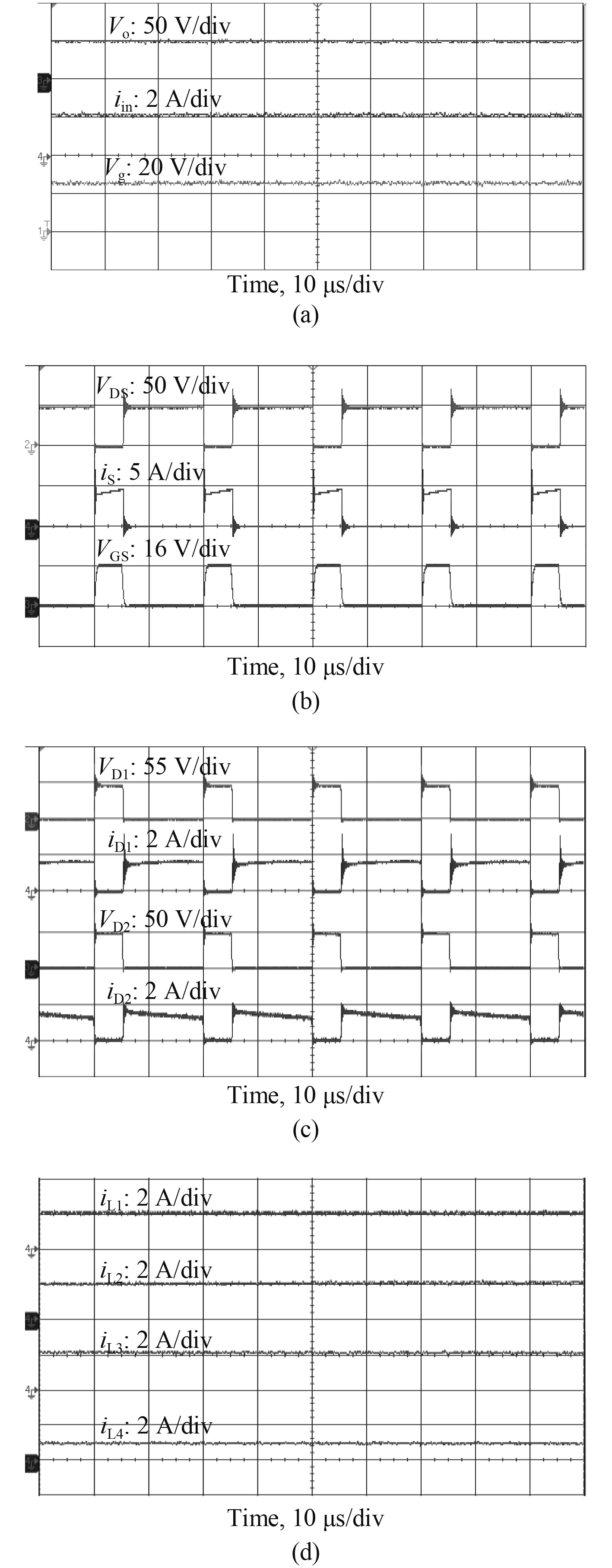
基于分析,设计100 W变换器样机进行实验。实验样机参数与仿真设计参数一致,验证所提出的深潜救生艇模拟器24 V电源新型变换器理论正确性,图6为D=0.25时变换器实验样机输入输出波形。
|
图 6 样机实验波形 Fig. 6 The experimental oscillograms of prototype |
图6(a)为变换器实验样机输入电压Vg、输出电压Vo及输入电流iin的实验波形,当输入电压Vg=25 V时,能够达到输出电压Vo=50 V,说明样机与所设计电路参数一致,且输出电压能够保持稳定;图6(b)为变换器实验样机开关管S两端电压VDS、所流过电流iS、驱动信号VGS波形图,当开关管导通时电路工作于状态1下,开关管关断时电路工作于状态2下;图6(c)为变换器实验样机二极管D1两端电压VD1、流经电流iD1、二极管D2两端电压VD2、流经电流iD2波形图;图6(d)为变换器实验样机电感L1,L2,L3,L4所流经电流iL1,iL2,iL3,iL4的波形图,其中iL1及iL4为输入电流及输出电流,通过波形图可知,输入、输出电流能够实现零纹波,以保证变换器稳定运行。
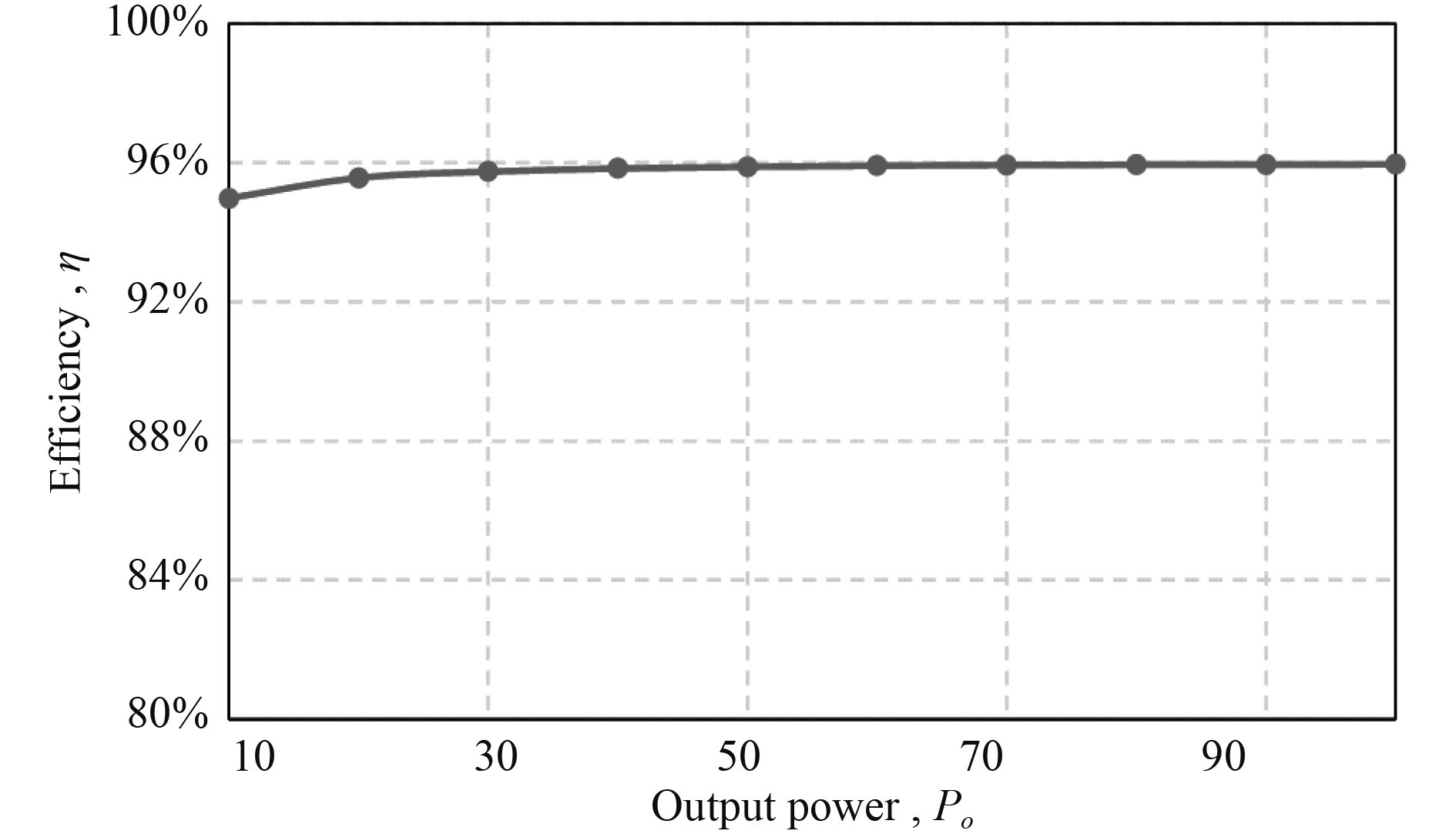
针对不同功率等级,对变换器样机进行测试,各功率等级下样机效率变化曲线如图7所示。在50 W情况下,变换器效率能够达到95.89%,随着功率等级的升高效率进一步提高,当100 W时,效率为95.96%。
|
图 7 样机效率曲线 Fig. 7 The efficiency curve of prototype |
本文提出的深潜救生艇模拟器24 V电源新型变换器,通过前级引入电感L1和L2能够有效减小输入电流纹波影响,实现电流零纹波输入,从而有效降低外界传导干扰对主24 V电源的影响,实现了电路稳定运行;通过引入电感L4能够在保证电路增益不变的情况下,实现对电路输出电流零纹波。不仅保证了主24 V电源工作时对外部设备的低干扰,同时能够达到优化器件选型,能够完全满足深潜救生艇模拟器对24 V电源低电磁干扰特性的需求。
| [1] |
许建. 现代潜艇设计理论与技术[M]. 哈尔滨: 哈尔滨工程大学出版社, 2019: 21–22.
|
| [2] |
张铁栋, 姜大鹏, 盛明伟, 等. 无人无缆潜水器技术[M]. 上海: 上海交通大学出版社, 2018: 38–40.
|
| [3] |
董鹏, 杨清轩, 刘洋. 国外新型外界援潜救生装备发展研究[J]. 舰船科学技术, 2018, 40(6): 152-157. DONG Peng, YANG Qing-xuan, LIU Yang. Research on the development of new types of foreign submarine rescue system[J]. Ship Science and Technology, 2018, 40(6): 152-157. DOI:10.3404/j.issn.1672-7649.2018.06.032 |
| [4] |
牟少芳. 深潜救生艇操纵训练模拟器控制系统研究与实现[D]. 青岛:青岛理工大学, 2017: 1–4.
|
| [5] |
钟后阳, 丁新平, 赵德林, 等. 深潜救生艇电力系统新型变换器研究[J]. 海军工程大学学报, 2021, 33(6): 37-43. DOI:10.7495/j.issn.1009-3486.2021.06.007 |
| [6] |
卢北虎, 刘飞, 金鑫, 等. 锂离子动力电池应用于深潜救生艇的可行性分析[J]. 船电技术, 2018, 38(5): 5-7. DOI:10.3969/j.issn.1003-4862.2018.05.002 |
| [7] |
高伟, 罗全明, 吕星宇, 等. 一种三绕组零纹波高增益DC/DC变换器[J]. 中国电机工程学报, 2018, 38(1): 232-241. DOI:10.13334/j.0258-8013.pcsee.161847 |
| [8] |
F. M. Shahir, E. Babaei, M. Farsadi. A new structure for nonisolated boost DC-DC converter[J]. Journal of Circuits, Systems and Computers, 2017, 26(1): 1142-1168. |
 2023, Vol. 45
