船舶作为海上运输的工具,在海上航行过程中会遇到极端天气影响,导致船舶颠簸、倾斜,且船舶通常运载十几甚至几十万吨的货物,受到海浪冲击,船体的总纵弯矩会发生变化[1-2],进而使船体结构的极限承载力发生变化。当其极限承载力达到极值时,区域船体结构会出现断裂现象,严重威胁船舶安全航行,因此研究船体结构的极限承载力对船舶安全航行非常重要。有很多学者研究船体结构极限承载力分析方法,丁仕风等[3]提出船体结构强度分析方法,该方法使用有限元构建船体结构模型后,在有限元环境中模拟冰荷载情况下的船体结构极限承载力。梅佳雪等[4]从船舶腐蚀角度出发,研究其结构极限承载力。虽然上述2种方法均可有效得到船舶结构的极限承载力,但在不同应用环境下,这2种方法均存在适用性不佳情况。为此本文提出总纵弯矩作用下船体结构的极限承载力分析方法,以提升船体结构极限承载力计算精度,为船舶维护提供有效数据。
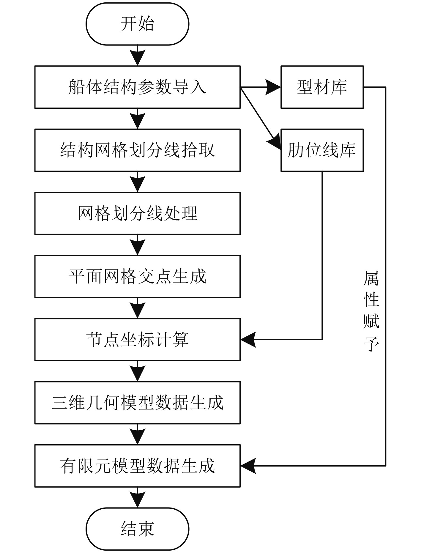
1 船体结构的极限承载力分析方法 1.1 船体结构有限元模型构建在分析船体结构的极限承载力时,需使用有限元构建船体结构模型,该模型构建流程如图1所示。利用有限元软件构建船体结构流程为:先将船体结构参数输入到有限元模型内,生成船体解耦型材库和肋位线库。然后拾取结构网格线并处理网格划分线后,生成船体结构平面网格交点[5],再以肋位线库内数据为基础,计算船体结构平面网格交点坐标后[6],生成三维几何模型数据。对型材库内数据赋予属性后,生成有限元模型数据,至此得到船体结构有限元模型。

|
图 1 船体结构有限元模型构建流程示意图 Fig. 1 Schematic diagram of building process of finite element model of hull structure |
船体结构纵向不受轴向应力作用,因此其纵弯力矩计算公式如下:
| $ {W_i} = {I_i} \cdot \sum\limits_{i = 1}^n {{\zeta _i}{A_i}}。$ | (1) |
式中:
船体结构板构件的应力值为其应变量函数[7],其表达公式如下:
| $ {\zeta _i} = {\zeta _i}({\varepsilon _i}),$ | (2) |
式中,
| $ {\varepsilon _i} = \phi ({y_i} - {y_0}) 。$ | (3) |
式中:
以上述公式结果为基础,构建船体结构总纵弯矩状态方程
| $ g(t) = {\sigma _i}{W_i}{A_i} - {Q_{st}} - {Q_{wt}} = 0。$ | (4) |
式中:
为方便分析船体结构承载力[8],将船体结构有限元模型进行简化处理,利用一维截面梁模拟船体结构,将船体划分为
| $ y'' = \frac{{ - g(t)}}{{EI}} 。$ | (5) |
式中:
利用有限差分方法求解式(5),将其微分问题转换成代数方程问题,则船体结构梁的有限差分方程为:
| $ {y_{i + 1}} - 2{y_i} + {y_{i - 1}} = - {s^2}\frac{{g(t)}}{{E{I_i}}}。$ | (6) |
式中:
从船体剖面平衡角度,分析总纵弯矩作用下,船体结构极限承载力。
| $ \left\{ \begin{gathered} \Delta {M_H} \\ \Delta {M_V} \\ \end{gathered} \right\} = \left\{ \begin{gathered} {R_H}{R_{HV}} \\ {R_{HV}}{R_V} \\ \end{gathered} \right\}\left\{ \begin{gathered} \Delta {\kappa _H} \\ \Delta {\kappa _V} \\ \end{gathered} \right\}g(t),$ | (7) |
| $ {R_H} = \sum {{{(E{U_e})}_i}} \sum {(y_i^2 - y_G^2)},$ | (8) |
| $ {R_V} = \sum {{{(E{U_e})}_i}} \sum {(z_i^2 - z_G^2)} ,$ | (9) |
| $ {R_{HV}} = \sum {{{(E{U_e})}_i}} \sum {(z_i^2 - z_G^2)} (y_i^2 - y_G^2) 。$ | (10) |
式中:
| $ {U_e} = U'\eta。$ | (11) |
式中:
| $ \eta = \frac{{\bar \zeta }}{{\bar \varepsilon }} $ | (12) |
式中:
经过上述步骤,依据船体结构剖面平衡方程,可得到结构抗弯强度承载力数值。
2 仿真分析以某远洋船舶作为实验对象,该船舶主尺度和中横剖面参数如表1所示。
|
|
表 1 船舶主尺度和中横剖面参数表 Tab.1 Parameters of ship's main dimensions and midsection |
依据表1内船舶主制度和中横剖面参数,建立船舶有限元模型,结果如图2所示。分析可知,本文方法构建的船舶有限元模型较为逼真,且船体中部界面区域可利用不同颜色标注,在模拟其在总纵弯矩作用下,船体结构的极限承载力可更加清晰呈现。综上结果,本文方法构架船舶有限元模型能力较强。
在有限元软件内模拟不同总纵弯矩情况下,分析船体结构单元平均应力变化趋势,结果如图3所示。分析可知,该船体结构单元的平均应力随着总纵弯矩数值的增加先呈现指数式上升趋势,再呈现迅速下降趋势,说明当船体结构的纵总弯矩数值越大,船体结构的平均应力越小,也就是说此时船体结构的承载力逐渐趋于极限值。

|
图 2 船舶有限元模型 Fig. 2 Finite element model of ship |

|
图 3 不同总纵弯矩情况下船体结构单元平均应力变化趋势 Fig. 3 Change trend of average stress of hull structural elements under different total longitudinal bending moments |
在有限元内模拟该船体在从船体结构中截剖面在总纵弯矩为2 000 N/m时,该船体结构中截剖面极限承载力分布状况,结果如图4所示。分析可知,当该船体结构受到2 000 N/m总纵弯矩时,其结构长边外侧的承载力数值较大,短边中部位置承载力数值略低,长边突出结构处,大部分结构颜色为黑色,说明其应力值为280 MPa,该应力值极为接近表1内,船舶材料屈服应力,说明该船体结构区域已达到极限应力值,存在较大结构屈服可能性。综上结果,本文方法可有效分析船体结构总纵弯矩为2 000 N/m时,结构的极限承载力,具备较好的应用效果。
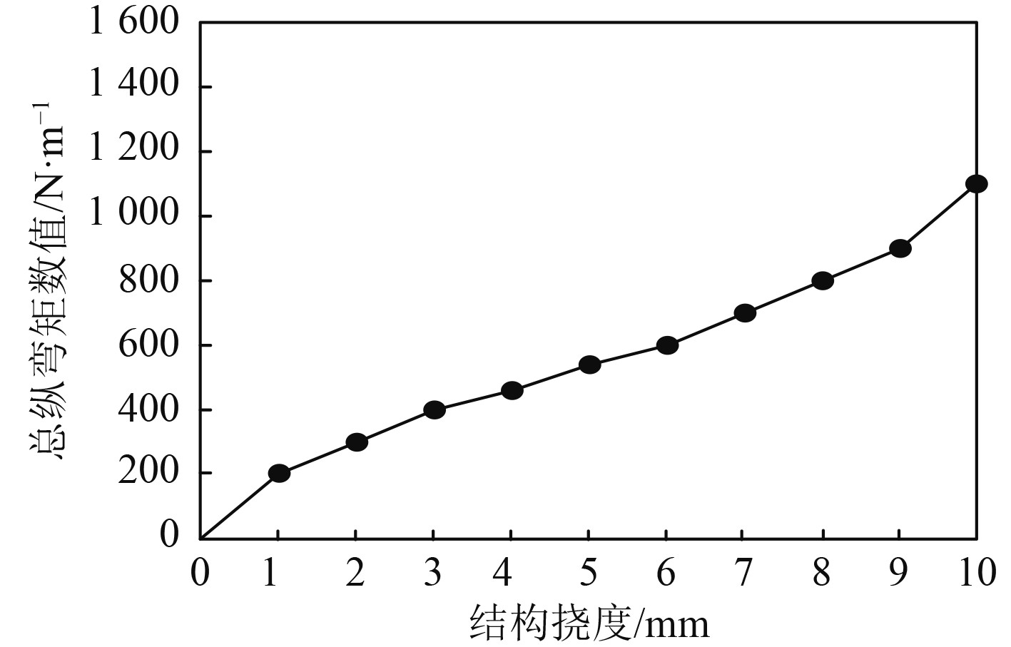
以船体结构挠度承载力作为指标,使用本文方法模拟其在不同总纵弯矩情况下,船体结构挠度与总纵弯矩的曲线拟合关系,结果如图5所示。分析可知,船体结构挠度承载力与总纵弯矩数值成正比例关系,但船体结构挠度随着总纵弯矩数值增加,其数值增加较为缓慢。上述结果说明:当船体结构受到的总纵弯矩数值越大,船体结构的挠度数值也越大,但船体结构挠度数值呈现稳步增加趋势。

|
图 4 船体结构中截面剖面极限承载力分布图 Fig. 4 Distribution diagram of ultimate bearing capacity of section in hull structure |

|
图 5 总纵弯矩与船体结构挠度承载力拟合曲线 Fig. 5 Fitting curve of total longitudinal bending moment and hull structure deflection bearing capacity |
船体结构的极限承载力分析对于船舶航行中维护来说非常重要,通过及时获得船体结构承载力,对其结构承载力不足位置及时维护,可有效保障船舶航行安全以及货物安全。本文方法将船体结构的总纵弯矩考虑其中,分析船体结构极限承载力,并对本文方法进行了多角度的验证。结果表明,本文方法分析船体结构极限承载力能力较为精准,具备一定的应用效果。
| [1] |
罗本永, 张升明, 陈忱. 基于冰载荷引起的船体结构疲劳损伤分析方法[J]. 船舶工程, 2020, 42(9): 19-24,69. LUO Benyong, ZHANG Shengming, CHEN Chen. Fatigue damage analysis method of ship structure based on ice load[J]. Ship Engineering, 2020, 42(9): 19-24,69. DOI:10.13788/j.cnki.cbgc.2020.09.04 |
| [2] |
罗白璐, 朱英富. 船用钢/复合材料接头疲劳损伤与承载性能试验研究[J]. 中国造船, 2020, 61(4): 70-76. LUO Bailu, ZHU Yingfu. Experimental study on residual capacity of marine steel/composite joint after fatigue damage[J]. Shipbuilding of China, 2020, 61(4): 70-76. |
| [3] |
丁仕风, 周利, 钟晨康, 等. 冰载荷作用下船体结构强度有限元分析方法[J]. 江苏科技大学学报(自然科学版), 2020, 34(1): 8-12,33. DING Shifeng, ZHOU Li, ZHONG Chenkang, et al. Finite element analysis method of hull structure strength under ice loads[J]. Journal of Jiangsu University of Science and Technology(Natural Science Edition), 2020, 34(1): 8-12,33. |
| [4] |
梅佳雪, 杜尊峰, 朱海涛. 基于随机腐蚀的船舶结构极限承载力研究[J]. 中国腐蚀与防护学报, 2022, 42(4): 662-668. MEI Jiaxue, DU Zunfeng, ZHU Haitao. Ultimate bearing capacity of ship structure based on random corrosion[J]. Journal of Chinese Society for Corrosion and Protection, 2022, 42(4): 662-668. |
| [5] |
刘昆, 严力宇, 张延昌, 等. 考虑中性轴偏转的碰撞损伤船体梁剩余极限强度分析[J]. 船舶工程, 2020, 42(5): 35-40. LIU Kun, YAN Liyu, ZHANG Yanchang, et al. Residual ultimate strength analysis of damaged ship hull after collision with consideration of neutral axis's shifting and rotation[J]. Ship Engineering, 2020, 42(5): 35-40. |
| [6] |
吴剑国, 伍友军, 李钧晖, 等. 船体梁约束扭转极限承载力计算的简化逐步迭代法[J]. 中国造船, 2022, 63(1): 188-197. WU Jianguo, WU Youjun, LI Junhui, et al. A simplified stepwise iterative method for calculating ultimate capacity of hull beam with restrained torsional strength[J]. Shipbuilding of China, 2022, 63(1): 188-197. |
| [7] |
吴梓鑫, 陈伟民. 基于模型试验的船舶纵倾优化技术研究[J]. 船舶力学, 2022, 26(4): 489-498. WU Zi-xin, CHEN Wei-min. Study on trim optimization technology based on ship model tests[J]. Journal of Ship Mechanics, 2022, 26(4): 489-498. |
| [8] |
柳光军, 孙哲, 李恒, 等. 基于CFD-FEM方法的船舶水弹性计算[J]. 中国造船, 2022, 63(1): 89-101. LIU Guangjun, SUN Zhe, LI Heng, et al. A coupled cfd-fem method for computation of ship hydroelasticity[J]. Shipbuilding of China, 2022, 63(1): 89-101. |
 2023, Vol. 45
