2. 国防科技大学 空天工程学院,湖南 长沙 410073;
3. 中国空气动力研究与发展中心,四川 绵阳 621000
2. College of Aerospace Science and Engineering, National University of Defense Technology, Changsha 410073, China;
3. China Aerodynamics Research and Development Center, Mianyang 621000, China
在海洋油气平台中,立管是连接海底管道和平台生产设备的重要设备,工作过程中受到海流、海浪和海风等各类环境载荷的作用。当海洋载荷的激励频率接近于管道自振频率时,海洋立管会诱发耦合共振,加剧立管疲劳破坏,可能造成严重的经济损失。因此,海洋立管流体动力学特性及流致振动等研究对深海油气设备开发有重要研究意义。
目前,对涡激振动(vortex-induced vibration,VIV)现象进行了深入研究,并提出多种振动抑制技术来克服海洋管道的涡激振动[1]。当海洋立管工作时,海洋波流绕过立管并在管后分离,产生交替脱落的漩涡,使管道承受周期性的流体作用力。当流体作用力的驱动频率(或漩涡脱落频率)接近于管道的固有频率时,海洋立管的横向振幅就会明显增大,出现涡激振动现象。该现象也被称为“频率锁定”现象,即管道振动会迫使漩涡脱落频率固定在立管固有频率附近,而不按漩涡本身的脱落频率脱落[2]。Iranpour等[3]对立管涡激振动进行了试验,发现雷诺数在2000~6000范围内立管存在4种不同形式的漩涡脱落形式。Sarpkaya[4]综述了涡激振动对柔性立管的影响,可利用管道受迫振动实验来分析自激振动特性。Blevins[5]发现当流体约化速度在6~7.5范围内,立管容易发生频率锁定现象,且载荷频率接近管道固有频率时,振动幅值会明显增大。娄敏等[6]实验研究了海洋立管内外流对涡激振动的共同影响。
随着计算机软件技术发展,涡激振动现象数值模拟的研究取得很大进展。白长旭等[7]利用Morison方程求解流体作用力,运用Abaqus软件对海洋立管进行了动力学分析,发现随海流流速增加,立管振动的位移先增大后减小。Mukundan等[8]系统研究了海洋立管的涡激振动理论,并对立管疲劳损伤进行了评估分析。Hartlen[9]分析了弹性支承圆柱的横向涡激振动特性,并建立了“尾流振子”经验模型。任大鹏[10]利用Fluent软件建立了立管涡激振动模型,研究了管道在均匀来流作用下横向振动的周期。赵鹏良[11]采用Fluent动网格技术,对立管低质量比和小阻尼等情况进行了计算,成功捕捉到“锁定”、“失谐”等现象。上述研究均采用现有软件计算,虽然能够定量研究海洋立管的涡激振动特性,但存在无法较好耦合海洋波浪以及计算精度差等问题。
在海洋波流载荷作用下,为准确计算海洋立管与流体的相互作用过程,在考虑立管与海洋波面相互影响的前提下,本文利用DNS和LES方法求解Navier-Stokes方程,利用IB法计算流体对海洋立柱的作用力,采用CLSVOF方法描述了海洋波浪的自由界面。与前期工作相比,本文将该方法应用到海洋立柱的数值模拟中,分析立柱的流固耦合特性及立柱对海洋波面的影响,为海洋立柱涡激振动特性的数值模拟提供高精度计算方法。
1 数值方法 1.1 Navier-Stokes方程流体求解器以海洋立柱直径D和来流速度
| $ \frac{{\partial {u_{\text{i}}}}}{{\partial t}} + \frac{{\partial \left( {{u_{\text{i}}}{u_{\text{j}}}} \right)}}{{\partial {x_{\text{j}}}}} = - \frac{{\partial p}}{{\partial {x_{\text{j}}}}} + \frac{1}{{Re}}\frac{{{\partial ^2}{u_{\text{i}}}}}{{\partial {x_{\text{j}}}{x_{\text{j}}}}} + {f_{\text{i}}} ,$ | (1) |
| $ \frac{{\partial {u_{\text{i}}}}}{{\partial {x_{\text{i}}}}} = 0 。$ | (2) |
式中:
| $ \frac{{\partial {{\bar u}_{{i}}}}}{{\partial t}} + \frac{{\partial \left( {{{\bar u}_{{i}}}{{\bar u}_{{j}}}} \right)}}{{\partial {x_{{j}}}}} = - \frac{1}{\rho }\frac{{\partial \bar p}}{{\partial {x_{{i}}}}} + {v_{{t}}}\frac{{{\partial ^2}{{\bar u}_{{i}}}}}{{\partial {x_{{j}}}\partial {x_{{j}}}}} - \frac{{\partial \tau _{{{ij}}}^d}}{{\partial {x_{{j}}}}} + {f_{{i}}} ,$ | (3) |
| $ \frac{{\partial {{\bar u}_{\text{i}}}}}{{\partial {x_{\text{i}}}}} = 0。$ | (4) |
式中:横线表示过滤后的变量,
N-S方程各变量分布在三维正交网格上,控制方程采用中心差分格式离散,由Runge-Kutta格式实现时间推进,其中压力泊松方程通过调用PETS库函数进行求解。本文所使用的N-S求解器在Linux系统下使用Fortran语言编写,采用MPI命令实现程序并行运算,具体算法详见文献[12]。本文计算所需硬件设备为国家超级计算长沙中心“天河”计算机,二维和三维算例分别采用64个和256个CPU进行并行计算。
1.2 CLSVOF方法将空气和海洋流体看作具有不同密度和粘度的单个系统,其N-S控制方程为:
| $ \frac{{\partial {\boldsymbol{u}}}}{{\partial {\text{t}}}} + {\boldsymbol{u}} \cdot \nabla {\boldsymbol{u}} = \frac{1}{\rho }\left( { - \nabla p + \nabla \cdot \left( {\mu {\mathbf{S}}} \right) + \rho g + \sigma {\mathbf{\kappa }}\delta \left( {{x_s}} \right) - \nabla \cdot {{\mathbf{\tau }}_{sgs}}} \right) ,$ | (5) |
| $ \nabla \cdot {\mathbf{u}} = 0。$ | (6) |
式中:u为速度,
| $ \rho = {\rho _{\text{a}}}\left( {1 - F} \right) + {\rho _{\rm{w}}}F ,$ | (7) |
| $ \mu = {\mu _{\text{a}}}\left( {1 - F} \right) + {\mu _{\rm{w}}}F 。$ | (8) |
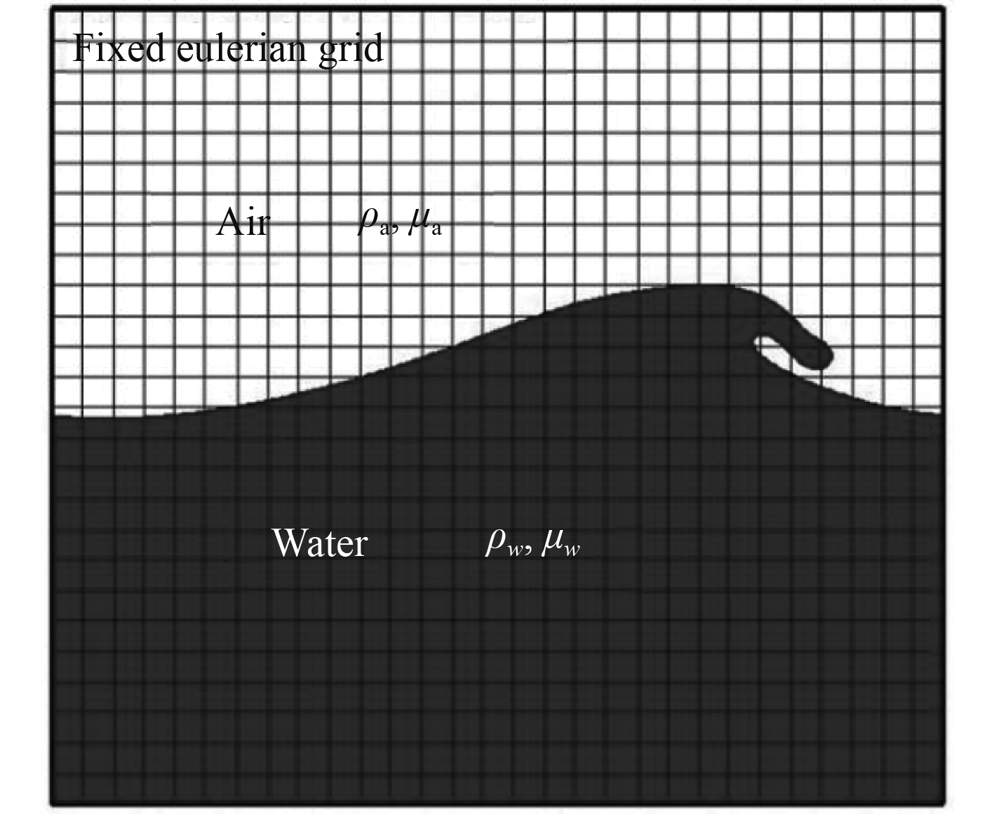
式中:下标“a”和“w”分别代表空气和海水。在空气中F值为0;在水中F值为1;在空气-海水界面的网格单元中F值为0 ~ 1。本文采用CLSVOF方法捕获空气-海水界面,迭代流程如图2所示。Level-set函数

|
图 2
Level-set函数
|
| $ \frac{{\partial \phi }}{{\partial {{t}}}} + \nabla \cdot \left( {u\phi } \right) = 0 ,$ | (9) |
| $ \frac{{\partial F}}{{\partial {{t}}}} + \nabla \cdot \left( {uF} \right) = 0 。$ | (10) |
在每个步骤中,利用Level-set函数对多相流界面进行重构,采用分段线性界面计算方法(piecewise-linear interface calculation,PLIC)进行计算,使F在重构界面上的通量得到精确解。当Level-set函数和VOF函数更新之后,F的函数值用来修正
|
图 1 多相流耦合系统 Fig. 1 Coupling system of multiphase flow |
采用Level-set方法确定海洋管道界面,管道截面为半径为R0的圆形,对应Level-set函数为:
| $ \varphi \left( x \right) = \sqrt {{{\left( {{{x - }}{{{x}}_0}} \right)}^2} + {{\left( {{{y - }}{{{y}}_0}} \right)}^2}} - {R_0} 。$ | (11) |
由于Level-set函数
在本文采用IB方法中,海洋波流对管道的作用力由体积力代替,体积力的大小由流场和边界条件决定。添加了体积力
| $ \frac{{\partial u}}{{\partial t}} + \nabla \cdot \left( {uu} \right) = - \nabla p + v{\nabla ^2}u + f ,$ | (12) |
动量方程的时间离散形式为:
| $ \frac{{{u^{{{n + 1}}}} - {u^{{n}}}}}{{\Delta t}} = \nabla \cdot \left( {uu} \right) - \nabla p + v{\nabla ^2}u + {f^{{{n + 1}}}} , $ | (13) |
在管道边界上,计算体积力
| $ {f^{{{n + 1}}}} = \frac{{{V^{{{n + 1}}}} - {u^{{n}}}}}{{\Delta t}} - \left( {\nabla \cdot \left( {uu} \right) - \nabla p + v{\nabla ^2}u} \right)。$ | (14) |
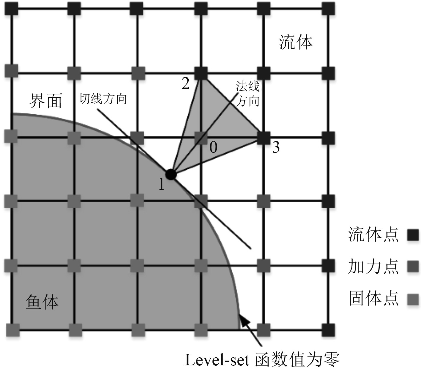
式(14)通过在加力点上施加速度边界条件,计算管道边界体积力来实现加力过程。在计算体积力过程中,加力点的位置通常不与边界位置重合,所以可根据周围固体点速度和流体点速度共同插值得到加力点速度。以图3为例,首先通过Level-set函数
|
图 3 基于Level-set函数和IB法的线性插值图 Fig. 3 The interpolation stencil for the Level-set function and IB method |
| $ \left( {{x_1},{y_1}} \right) = \left( {{x_0} - {n_{\text{x}}}{\varphi _0},{y_0} - {n_{\text{y}}}{\varphi _0}} \right)。$ | (15) |
式中:
| $ \left\{ {\begin{array}{*{20}{c}} {\left[ {{x_2},{y_2}} \right] = \left[ {{x_0},{y_0} + {\text{sign}}\left( {{n_{\text{y}}}} \right) \cdot \Delta y} \right]},\\ {\left[ {{x_3},{y_3}} \right] = \left[ {{x_0} + {\text{sign}}\left( {{n_{\text{x}}}} \right) \cdot \Delta x,{y_0}} \right]} 。\end{array}} \right. $ | (16) |
在管道壁面附近时,速度场近似满足线性分布,所以近壁流场采用多项式插值方法来确定加力点速度。设加力点0速度
| $ {u_{{\text{0i}}}} = {b_{\text{1}}} + {b_{\text{2}}}{x_{\text{0}}} + {b_{\text{3}}}{y_{\text{0}}} 。$ | (17) |
式中:
| $ \left[ {\begin{array}{*{20}{c}} {{b_{\text{1}}}} \\ {{b_{\text{2}}}} \\ {{b_{\text{3}}}} \end{array}} \right] = {{\mathbf{A}}^{{{ - 1}}}}\left[ {\begin{array}{*{20}{c}} {{u_{{\text{1i}}}}} \\ {{u_{{\text{2i}}}}} \\ {{u_{{\text{3i}}}}} \end{array}} \right] = {\left[ {\begin{array}{*{20}{c}} {\text{1}}&{{x_{\text{1}}}}&{{y_{\text{1}}}} \\ {\text{1}}&{{x_{\text{2}}}}&{{y_{\text{2}}}} \\ {\text{1}}&{{x_{\text{3}}}}&{{y_{\text{3}}}} \end{array}} \right]^{{{ - 1}}}}\left[ {\begin{array}{*{20}{c}} {{u_{{\text{1i}}}}} \\ {{u_{{\text{2i}}}}} \\ {{u_{{\text{3i}}}}} \end{array}} \right]\left( {i = 1,2,3} \right)。$ | (18) |
通过求解系数矩阵
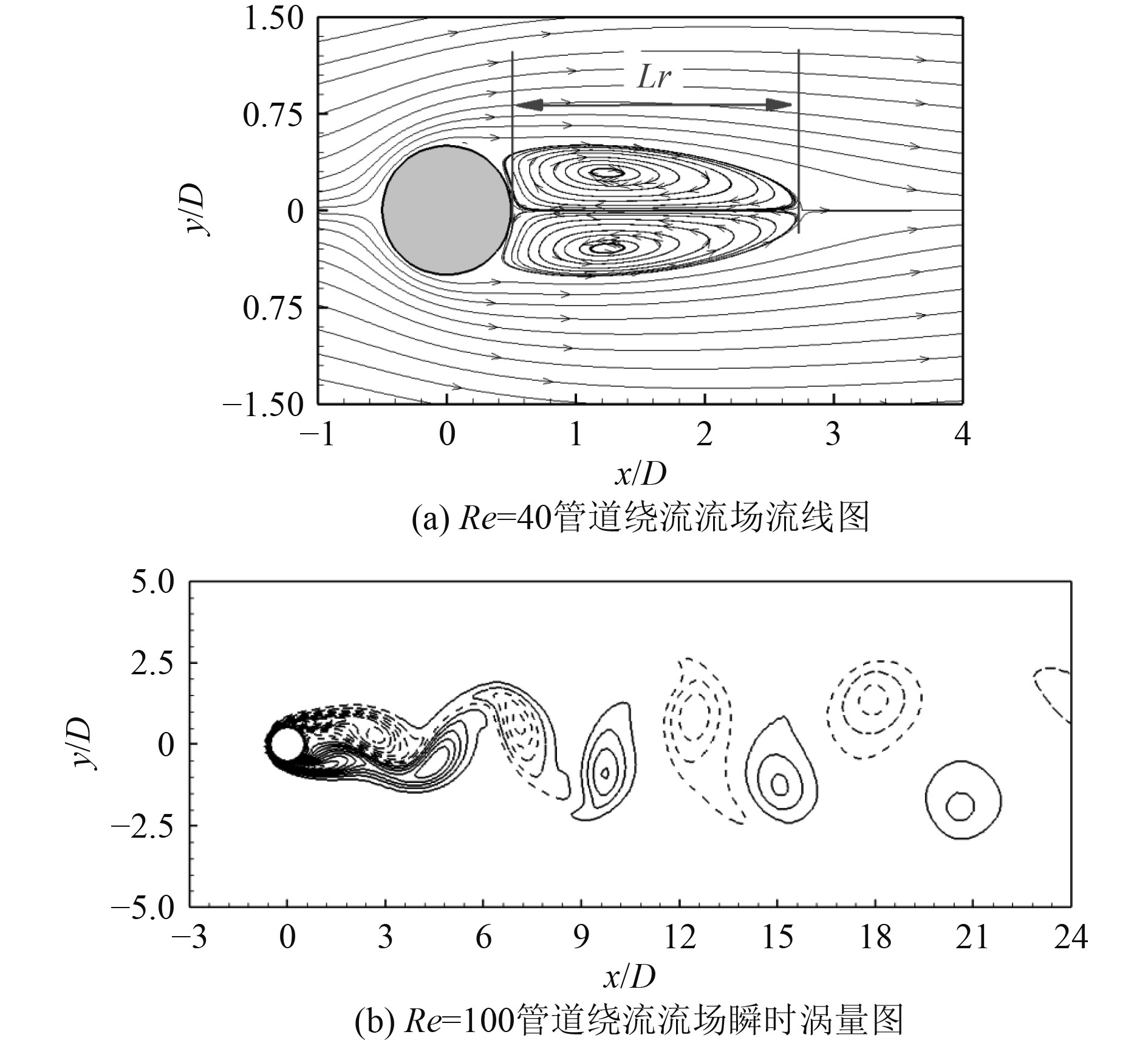
在海洋管道静止绕流研究中,定义雷诺数Re为
|
图 4 不同雷诺数下海洋管道绕流的流场特征 Fig. 4 The flow field characteristics of marine pipe at different Reynolds numbers |
表1列出了Re=40时管道平均阻力系数
|
|
表 1 Re=40时海洋管道计算结果对比 Tab.1 Result comparisons for the flow around marine pipe at Re=40 |
|
|
表 2 Re=100时海洋管道计算结果对比 Tab.2 Result comparisons for the flow around marine pipe at Re=100 |
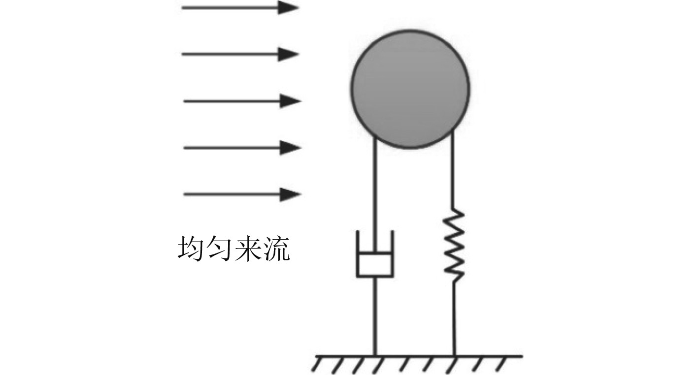
作为典型的流固耦合问题,海洋管道涡激振动的实验和数值模拟研究较多[20]。本文利用CLSVOF-IB方法研究模拟海洋管道的涡激振动特性,如图5所示。海洋管道简化为一个弹性固定圆柱绕流模型,圆柱直径为D。该模型只在横向振动,侧向位移为Y0,无量纲化的控制方程为:
|
图 5 海洋管道涡激振动算例 Fig. 5 The vortex vibration case of an ocean pipeline |
| $ \ddot y + 2\zeta \left( {\frac{2}{{{U_{red}}}}} \right)\dot y + {\left( {\frac{{2{\text{π}} }}{{{U_{red}}}}} \right)^2}y = \frac{1}{{2n}}{C_L}。$ | (19) |
式中:y为无量纲化位移Y0/D;
在海洋管道涡激振动算例中,计算域、网格尺寸分布、时间步长和进出口边界条件设置均与管道绕流相同
|
|
表 3 海洋管道涡激振动算例参数 Tab.3 Example parameters of vortex-induced vibration of marine pipeline |
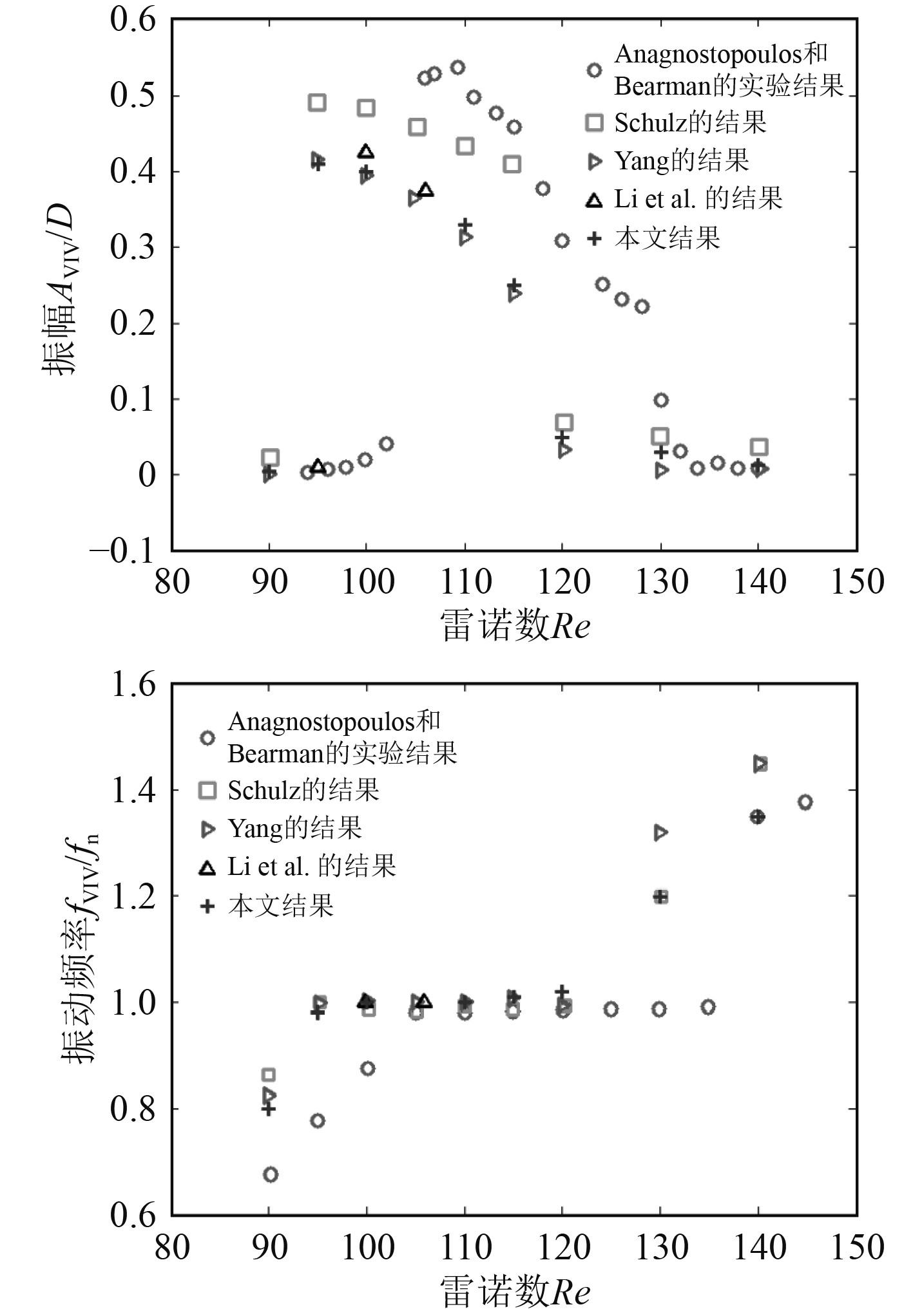
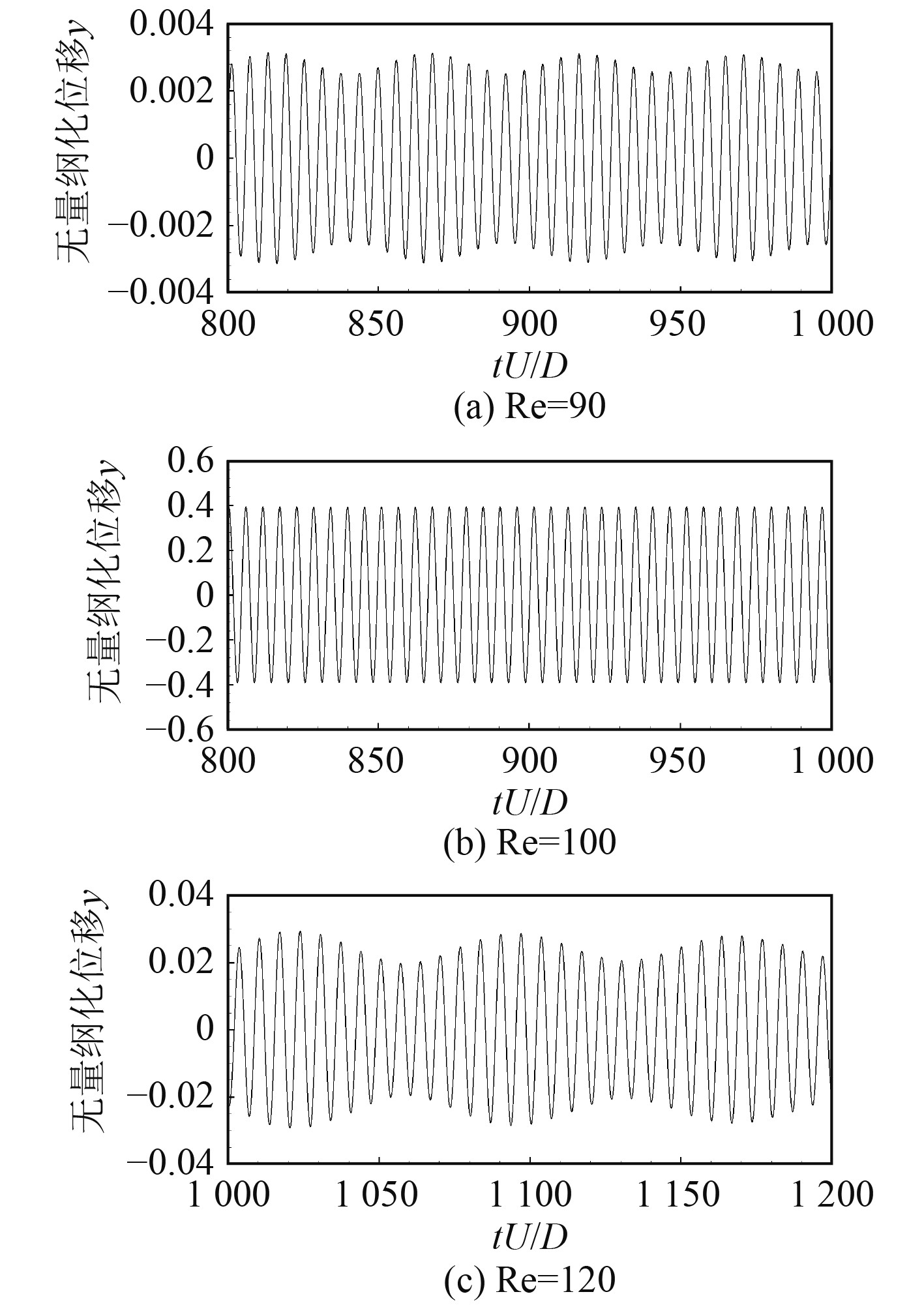
在稳定状态下,涡激振动圆柱的最大振幅和振动频率如图6所示。对于算例A、算例C和算例E,涡激振动圆柱振动位移随时间变化情况如图7所示。结果表明,当系统固有频率在锁频频率之内,圆柱侧向位移明显增大,无量纲化位移达到0.4;当系统固有频率在锁频频率之外,圆柱侧向位移较小,最大位移约为0.003。总体上,当系统固有频率远离尾涡脱落频率,圆柱振幅较小,阻力系数振荡较小;但当系统处于“锁频频率”状态(算例C和算例D),圆柱振动幅值明显的增加,该结果与文献[23]结论相同。
|
图 6 海洋管道最大位移和振动频率随雷诺数的变化情况 Fig. 6 The maximum displacement and vibration frequency of marine pipeline varied with Re numbers |
|
图 7 海洋管道的稳态位移 Fig. 7 Steady displacement of marine pipeline |
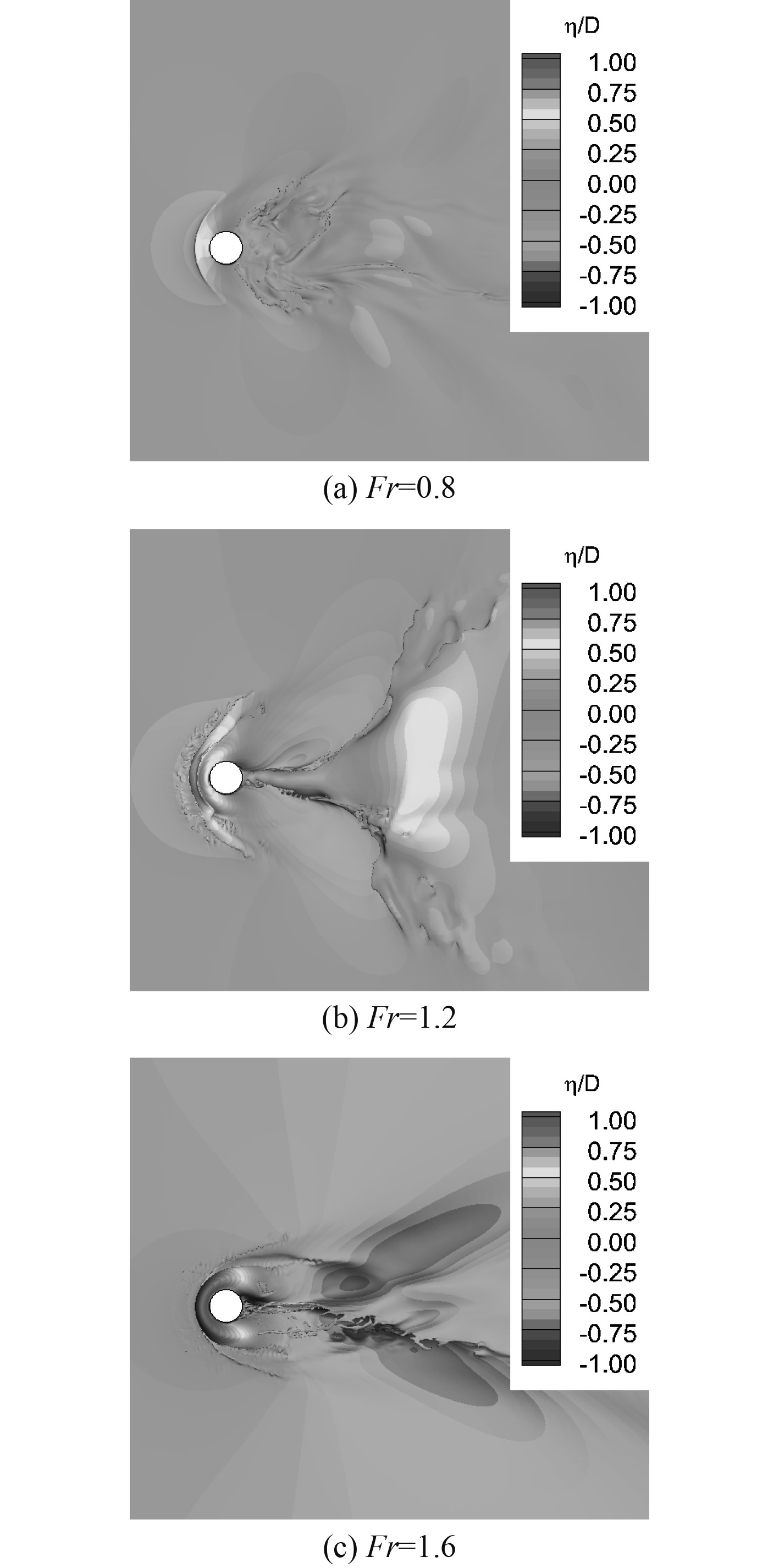
为验证CLSVOF-IB数值方法对海洋波面的捕捉程度,设置管道与海洋波面相互作用的算例。以入口速度U和管道直径D为约化参数,设置雷诺数Re为2.7×10⁴,Fr参数分别为0.8,1.2和1.6,其中Froude数定义为

|
图 8 海洋管道与自由波面算例示意图 Fig. 8 Schematic diagram of marine pipeline interacted with free surface |
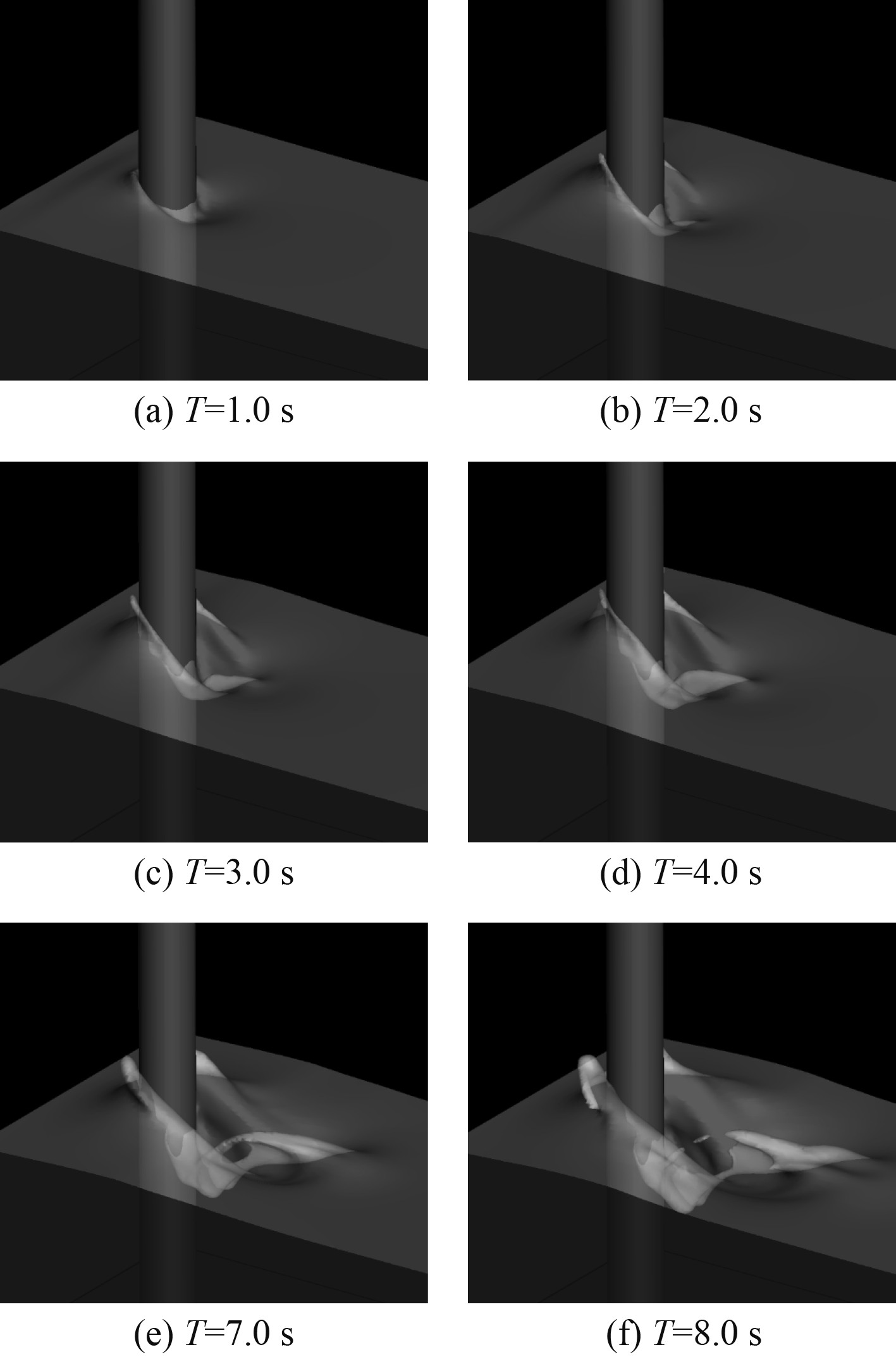
当Fr数为1.2时,管道绕流对应自由波面变化的俯视图如图9所示,当Fr数分别为0.8,1.2和1.6时,管道对海洋波面影响的俯视图如图10所示。结果表明CLSVOF-IB数值算法能够较好捕捉海洋管道与流体自由界面的相互作用,计算多相流界面时有较高精度。
|
图 9 海洋管道对波面影响波面变化图 Fig. 9 Effect of marine pipeline on wave surface |
|
图 10 不同Fr数海洋管道波面变化的俯视图 Fig. 10 Top view of wave surface of marine pipeline varied with Fr numbers |
针对海洋管道在外界激振力引发的流致振动问题,本文结合CLSVOF方法和IB方法优势,建立模拟海洋管道与流体相互作用的流固耦合模型,采用Level-set距离函数的特性确定海洋管道边界,利用浸入边界法计算流体介质对管道的作用力,采用CLSVOF方法模拟海洋的自由波面。通过改变流体Fr数,分析了管道与海洋自由波面的相互作用过程。结果表明CLSVOF-IB方法能够准确有效分析海洋管道的涡激振动特性,并且能较好捕捉海洋管道与自由波面的相互作用过程。
| [1] |
蒋武杰. 内波、海流与波浪中深海立管动力特性研究[D]. 上海: 上海交通大学, 2012.
|
| [2] |
唐友刚, 沈国光, 刘丽琴. 海洋工程结构动力学[M]. 天津: 天津大学出版社, 2008.
|
| [3] |
IRANPOUR M, TAHERI F, VANDIVER J K. Structural life assessment of oil and gas risers under vortex-induced vibration[J]. Marine Structures, 2008, 21: 353-373. DOI:10.1016/j.marstruc.2008.02.002 |
| [4] |
SARPKAYA T. A critical review of the intrinsic nature of vortex-induced vibrations[J]. Journal of Fluids and Structures, 2004, 19(4): 389-447. DOI:10.1016/j.jfluidstructs.2004.02.005 |
| [5] |
BLEVINS R D. Flow-induced vibration[M]. New York: Van Nostrand, 1999.
|
| [6] |
娄敏. 海洋输流立管涡激振动试验研究及数值模拟[D]. 青岛: 中国海洋大学, 2007.
|
| [7] |
白长旭, 黄一, 刘刚. 波流耦合作用下的立管涡激振动分析研究[J]. 中国海洋平台, 2008, 23(2): 18-24. DOI:10.3969/j.issn.1001-4500.2008.02.004 |
| [8] |
MUKUNDAN H, HOVER F S, TRIANTAFYLLOU M S. A systematic approach to riser VIV response reconstruction[J]. Journal of Fluids and Structures, 2010, 26(5): 722-746. DOI:10.1016/j.jfluidstructs.2010.04.001 |
| [9] |
HARTLEN R T, CURRIE I G. Lift oscillation model for vortex-induced vibration[J]. Engineering Mechanics, 1970, 96: 577-591. |
| [10] |
赵鹏良, 王嘉松, 蒋世全, 等. 海洋立管涡激振动的流固耦合模拟计算[J]. 海洋技术, 2010, 29(3): 74-77. |
| [11] |
任大朋, 黄一, 刘刚. 一种基于Ansys和FLUENT的海洋立管的涡激响应分析方法[J]. 中国海洋平台, 2007, 22(4): 32-36. DOI:10.3969/j.issn.1001-4500.2007.04.006 |
| [12] |
CUI Z, YANG Z, JIANG H, et al. A sharp interface immersed boundary method for simulating incompressible flows with arbitrarily deforming smooth boundaries[J]. International Journal of Computational Methods, 2017, 14, 1750080.
|
| [13] |
KIM J, KIM D, CHOI H. An immersed boundary finite volume method for simulations of flow in complex geometries[J]. Journal of Computational Physics, 2001, 171: 132-150. DOI:10.1006/jcph.2001.6778 |
| [14] |
YE T, MITTAL R, UDAYKUMAR H S, et al. An accurate Cartesian grid method for viscous incompressible flows with complex immersed boundaries[J]. Journal of Computational Physics, 1999, 156: 209-240. DOI:10.1006/jcph.1999.6356 |
| [15] |
TSENG Y H, FERZIGER J H. A ghost-cell immersed boundary method for flow in complex geometry[J]. Journal of Computational Physics, 2003, 192: 593-623. DOI:10.1016/j.jcp.2003.07.024 |
| [16] |
DIAS A, MAJUMDAR S. Numerical computation of flow around a circular cylinder[R]. Technical Report, PS II Report, BITS Pilani, India.
|
| [17] |
PARK J, KWON K, CHOI H. Numerical solutions of flow past a circular cylinder at Reynolds numbers up to 160[J]. KSME International Journal, 1998, 12(6): 1200-1205. DOI:10.1007/BF02942594 |
| [18] |
FORNBERG B. A numerical study of steady viscous flow past a circular cylinder[J]. Journal of Fluid Mechanics, 1980, 98: 819-855. DOI:10.1017/S0022112080000419 |
| [19] |
LIU C, ZHENG X, SUNG C H. Preconditioned multigrid methods for unsteady incompressible flows[J]. Journal of Computational Physics, 1998, 139: 35-57. DOI:10.1006/jcph.1997.5859 |
| [20] |
WILLIAMSON C H K, GOVARDHAN R. Vortex-induced vibrations[J]. Annual Review of Fluid Mechanics, 2004, 36: 413-455. DOI:10.1146/annurev.fluid.36.050802.122128 |
| [21] |
ANAGNOSTOPOULOS P, BEARMAN P W. Response characteristics of a vortex excited cylinder at low Reynolds numbers[J]. Journal of Fluids and Structures, 1992, 6: 39-50. DOI:10.1016/0889-9746(92)90054-7 |
| [22] |
SCHULZ K W, KALLINDERIS Y. Unsteady flow structure interaction for incompressible flows using deformable hybrid grids[J]. Journal of Computational Physics, 1998, 143: 569-597. DOI:10.1006/jcph.1998.5969 |
| [23] |
LI L, SHERWIN S J, BEARMAN P W. A moving frame of reference algorithm for fluid/structure interaction of rotating and translating bodies[J]. International Journal for Numerical Methods in Fluids, 2002, 38: 187-206. DOI:10.1002/fld.216 |
 2022, Vol. 44
