2. 鹤壁职业技术学院,河南 鹤壁 458030
2. Hebi Polytechnic, Hebi 458030, China
通常,船载无人机采用的导航系统为惯性导航系统,通过采集无人机的速度、加速度、位姿等信息[1],整合为船载无人机的导航信号,因此,船载无人机惯性导航系统的工作精度是无人机执行任务的重要保障。
本文以船载无人机惯性导航系统的数据融合算法为研究方向,分别介绍了惯性组合导航系统的原理、无人机惯性导航系统的坐标转换、惯性导航系统的关键组件以及异步信息融合和误差分析。
1 船载无人机惯性导航系统的数据融合需求本文研究的船载无人机采用捷联惯性导航(SINS)系统,这种导航系统区别于传统的惯性导航系统,主要有下述几点:
1)陀螺仪等传感器直接安装在船载无人机上,采集无人机的加速度和旋转速率等信息;
2)通过数学矩阵的方法进行无人机位置、速度等信息的推算,陀螺仪和加速度计采集一定坐标系下的船载无人机数据,然后经过坐标转换和数学推算,获取当前导航坐标系下正确的目标分量。
3)姿态矩阵是船载无人机SINS系统的核心,计算机的强大性能保证数学矩阵的解算效率。
如图1所示,船载无人机捷联惯性导航系统的工作过程为:

|
图 1 船载无人机捷联惯性导航系统工作原理图 Fig. 1 Working principle diagram of shipborne UAV strapdown inertial navigation system |
首先,捷联惯性导航系统的加速度传感器和陀螺仪采集无人机的加速度、角速度、位姿等信息,然后进入误差补偿计算模块。由于加速度传感器和陀螺仪输出的数据都是建立在载体坐标系下的,因此,需要将加速度传感器和陀螺仪输出的数据进行坐标转换,换算到导航坐标系下,并进行姿态解算和航向解算。最后,将最终的船载无人机位置、速度和姿态角[2]等导航信息发送至导航系统的控制与显示模块,供查阅和调用。
2 船载无人机惯性导航系统的坐标转换和关键部件 2.1 船载无人机惯性导航系统的坐标转换船载无人机惯性导航系统的各类传感器,如陀螺仪、磁力计、速度仪和加速度计等,采集的初始信息都是基于无人机自身载体的坐标系下,因此必须进行坐标转换才能获取准确的导航信息。
建立船载无人机惯性导航系统的坐标系如图2所示。

|
图 2 船载无人机惯性导航系统的坐标系 Fig. 2 Coordinate system of inertial navigation system of ship borne UAV |
如图2,无人机导航坐标系
| $ \left[ {\begin{array}{*{20}{c}} {{r_{{x_2}}}} \\ {{r_{{y_2}}}} \\ {{r_{{Z_2}}}} \end{array}} \right] = \left[ {\begin{array}{*{20}{c}} {\cos \alpha }&{\sin \alpha }&0 \\ { - \sin \alpha }&{\cos \alpha }&0 \\ 0&0&1 \end{array}} \right]\left[ {\begin{array}{*{20}{c}} {{r_{{x_1}}}} \\ {{r_{{y_1}}}} \\ {{r_{{z_1}}}} \end{array}} \right] \text{,} $ |
令变换矩阵
无人机惯性系统的坐标系
| $ O - {X_1}{Y_1}{Z_1} \to O - {X_2}{Y_2}{Z_2} \to O - {X_n}{Y_n}{Z_n} \text{,} $ |
依次可得变换矩阵为:
| $ {\boldsymbol{M}}_1^2 = \left[ {\begin{array}{*{20}{c}} 1&0&0 \\ 0&{\cos \theta }&{\sin \theta } \\ 0&{ - \sin \theta }&{\cos \theta } \end{array}} \right] \text{,} {\boldsymbol{M}}_n^1 = \left[ {\begin{array}{*{20}{c}} {\cos \psi }&{ - \sin \psi }&0 \\ {\sin \psi }&{\cos \psi }&0 \\ 0&0&1 \end{array}} \right] \text{,} $ |
得到无人机的导航姿态矩阵如下式:
| $ {\boldsymbol{M}}_n^b = {\boldsymbol{M}}_1^2{\boldsymbol{M}}_n^1 = \left[ {\begin{array}{*{20}{c}} {\cos \gamma }&0&{ - \sin \gamma } \\ 0&1&0 \\ {\sin \gamma }&0&{\cos \gamma } \end{array}} \right]\left[ {\begin{array}{*{20}{c}} {\cos \psi }&{ - \sin \psi }&0 \\ {\sin \psi }&{\cos \psi }&0 \\ 0&0&1 \end{array}} \right] 。$ |
1)惯性导航组件
本文研究的船载无人机惯性导航系统采用的惯导组件为M2-M型组件,该组件将磁力计、角速度传感器、加速度传感器集成为一体,并在集成组件上外接了HMR3000型电子罗盘[3],为船载无人机提供精确的位置、姿态信息。
2)GPS
GPS可以为船载无人机提供全天候、高精度的定位信息,目前,GPS技术已经具备更高的集成特性,模块体积更小,性能更强。船载无人机惯导系统使用GPS进行三维定位、测速、授时等功能。
3)多普勒测速仪DVL
为了提高船载无人机速度采集的精度,采用基于电磁波测速的多普勒测速仪,根据测速仪发射信号和采集信号之间的关系获取舰载无人机的准确速度。
多普勒测速仪DVL的测速原理如图3所示。

|
图 3 多普勒测速仪DVL的测速原理 Fig. 3 Velocity measurement principle of Doppler velocimeter DVL |
假定船载无人机对于多普勒测速仪DVL[4]信号发射点的速度为
| $ {f^\prime } = \frac{{{v_0}}}{v}f 。$ |
电磁波经过船载无人机发射后的信号频率为
| $ {f^{\prime \prime }} = \frac{{v + {v_0}}}{v}{f^\prime } = \frac{{v + {v_0}}}{{v - {v_0}}}f \text{,} $ |
系统的多普勒频移为:
| $ {f_d} = {f^{\prime \prime }} - f = \frac{{2{v_0}}}{{v - {v_0}}}f \text{,} $ |
解算方程可得到无人机的速度为:
| $ \begin{gathered} v = \left( {1 + \frac{{2f}}{{{f_d}}}} \right){v_0} \text{,} \\ {v_0} = \left( {\frac{{{f_d}}}{{2f + {f_d}}}} \right)v \text{。} \\ \end{gathered} $ |
重点介绍惯性导航系统的多传感器异步信息融合过程,将载体坐标系的信息转换到导航坐标系下,进行下一步融合。
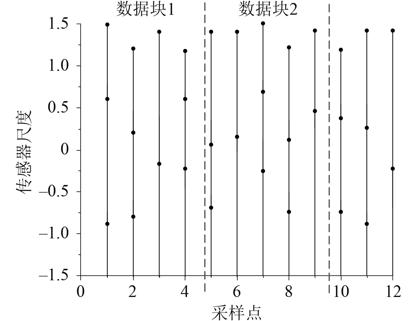
由于惯性导航系统内的多传感器采集频率各不相同,设惯性导航系统内共有N个导航传感器
| $ S_i = \frac{{{S_N}}}{{{n_i}}} \text{,} $ |
式中
根据多尺度理论,建立无人机惯性导航系统的信号采集方程为:
| $ \begin{gathered} x(N,k + 1) = {\boldsymbol{\varPhi}} (N,k)x(N,k) + w(N,k) ,\\ z(i,k) = {\boldsymbol{H}}(i,k)x(i,k) + v(i,k) 。\\ \end{gathered} $ |
式中:
图4为不同尺度传感器采样点与时刻的关系图。

|
图 4 不同尺度的传感器采样点与时刻的关系图 Fig. 4 Relationship between sampling points and time of sensors with different scales |
1)船载无人机姿态信号融合
假设无人机的方位角为
| $ \left\{ \begin{gathered} x = \rho \sin {\theta _t} ,\\ y = \rho \cos {\theta _t} ,\\ \end{gathered} \right. $ |
考虑惯导传感器元件的硬件误差和外界因素,建立无人机姿态的距离误差和角度误差为:
| $ \begin{gathered} {\sigma _l} = {\sigma _0}\cos {\theta _t} + \rho \sin {\theta _t} ,\\ {\sigma _s} = {\sigma _0}\sin {\theta _t} + \rho \cos {\theta _t} ,\\ \end{gathered} $ |
可得无人机的真实坐标为
| $ {\left( {{x_0},{y_0},{z_0}} \right)^{\rm{T}}} = \left[ \begin{gathered} \cos {\theta _t} \hfill \\ 1 \hfill \\ \sin {\theta _t} \hfill \\ \end{gathered} \right] \times {\left( {\rho ,{\theta _t}} \right)^{\rm{T}}} \times \left[ \begin{gathered} {\sigma _l} \hfill \\ {\sigma _s} \hfill \\ \end{gathered} \right] 。$ |
2)船载无人机多传感器信号的时间关联
由于惯导系统的多传感器采样频率不同,信号的扫描周期也不同[6],因此,需要将传感器数据进行时间关联。
建立信号关联判断方程为:
| $ \left| {{k_{A,j}} - {k_{B,j}}} \right| < C\;\;,j = 0,1,\cdots ,n \text{,} $ |
其中:
建立传感器的时间融合方程为:
| $ \left\{ \begin{gathered} x\left( k \right) = x\left( {{t_i}} \right) + \frac{{\sin \left( {S\left( {{t_i}} \right) \cdot \left( {k - {t_i}} \right)} \right)}}{{60}} ,\\ y\left( k \right) = y\left( {{t_i}} \right) + \frac{{\cos \left( {S\left( {{t_i}} \right) \cdot \left( {k - {t_i}} \right)} \right)}}{{60}} 。\\ \end{gathered} \right. $ |
式中
3)误差分析
建立多传感器的融合信号状态方程为:
| $ S(x + 1) = \phi (x + 1,x)S(x) + H(x) \text{,} $ |
式中:
信号的滤波方程为:
| $ \mathop {\rm{S}}\limits^{\smallfrown} (x/x - 1) = \phi (x/x - 1)\mathop {\rm{S}}\limits^{\smallfrown} (x) ,$ |
得到信号融合的误差方程为:
| $ \eta \left( {x/x} \right) = {\left[ {1 - S(x)C\left( x \right)P(x/x - 1)} \right]^{\frac{1}{2}}} 。$ |
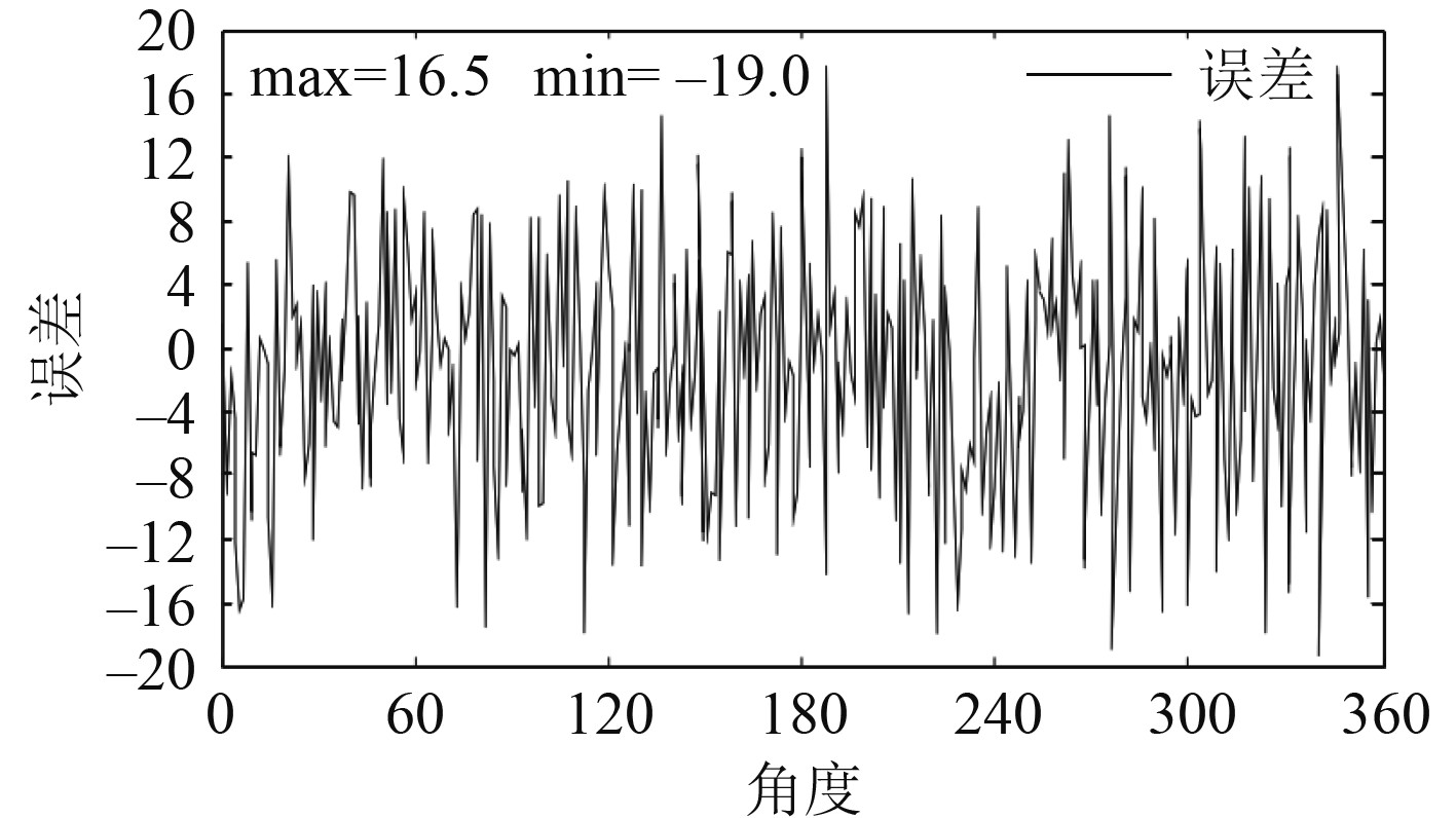
采集0~360°无人机航行角度的信号融合误差,得到图5所示曲线。

|
图 5 0~360°无人机航行角度的信号融合误差曲线 Fig. 5 Signal fusion error curve of 0~360 ° UAV navigation angle |
船载无人机作为执行特种作业的设备,目前处于高速发展阶段,本文研究的侧重点是舰载无人机惯性导航系统的数据融合算法,包括惯性导航系统多传感器的坐标转换、惯性导航系统的关键组件及组件工作原理,最后针对惯性导航系统的传感器实时数据融合进行了建模与误差特性分析。
| [1] |
杨功流, 李士心, 姜朝宇. 地磁辅助惯性导航系统的数据融合算法[J]. 中国惯性技术学报, 2007, 15(1): 4. |
| [2] |
王勇军, 李智, 李翔. 无人机磁惯导系统中航向校正的双内积算法[J]. 仪器仪表学报, 2019, 40(9): 8. |
| [3] |
刘卫华, 高贺, 高超. 适用于巡检无人机的捷联惯导系统快速对准研究[J]. 系统仿真技术, 2019(4): 5. |
| [4] |
许多伦, 蔡宇哲, 薛松浩, 等. 基于惯导以及GPS的飞行器定位系统[J]. 信息记录材料, 2018, 19(11): 2. |
| [5] |
王勇军, 李智, 李翔. 无人机磁惯导系统中陀螺仪的叉积标定算法[J]. 仪器仪表学报, 2020(4): 10. |
| [6] |
卢鑫, 练军想, 吴美平. 高精度舰载惯性导航系统的重力影响研究[J]. 导航与控制, 2010, 9(4): 15-21. |
| [7] |
罗续成. 惯性导航系统/双星距离差组合导航算法的可行性研究[J]. 遥测遥控, 2002(6): 7. |
 2022, Vol. 44
