在浅海海洋环境中,由于季节变化,表层区域海水温度较高,使得其电导率高于中间层和底层海水。根据海水电导率不同可以将模型分成不同物性参数的分层结构。因此可以将水平电偶极子在浅海海洋环境中空气-海水-海床3层模型拓展成空气-海水多层-海床等N层模型,通过水平电偶极子在海水分层的多层模型中构建数学模型,进行理论推导和仿真计算,以达到更加逼近于真实海洋环境中水平交变电偶极子水下电场分布特性的完整呈现。本文将分析水平电偶极子在空气-3层海水-海床5层模型中的电场分布规律和衰减特性。
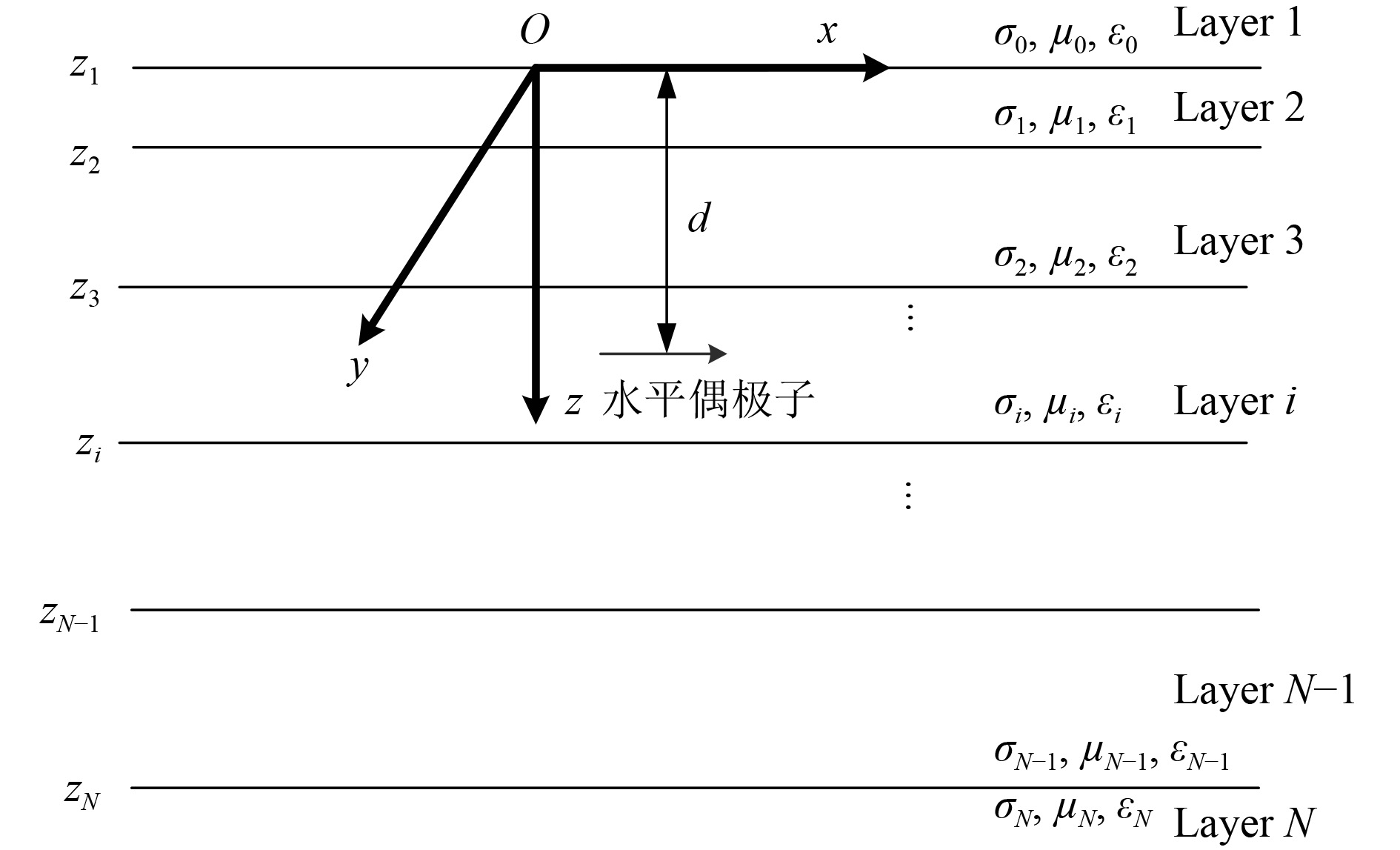
1 N层模型理论[3-5]将海洋环境等效为5层水平层状各向同性均匀导电媒质,根据边界条件求解矢量位在各层中满足的微分方程十分困难。与空气—海水—海床3层模型解法不同,本文将5层海洋环境模型延伸为N层海洋环境模型,水平电偶极子源分解为TE和TM极化模式,利用TE和TM的矢量位求解通解。再求偶极子源的特解,并与通解相加得到边值问题的解,其中通解中的待定系数可利用反射系数确定。对傅氏变换空间中的解进行二维反傅氏变换(或反汉克尔变换)可得到最终解。将矢量位的解代入场强公式中可得到海床分层环境中偶极子电磁场的解。
|
图 1 时谐水平电偶极子在N层海洋环境中示意图 Fig. 1 Schematic diagram of a time-harmonic horizontal electric dipole in an N-layer marine environment |
矢量位
| $\begin{split}& {{\rm{A}}_{\rm{x}}}(\rho ) = \frac{1}{{2\text{π} }}\int\nolimits_0^\infty {{{{\rm{\hat A}}}_{\rm{x}}}(\lambda ,z){{\rm{J}}_0}(\rho \lambda )\lambda {\rm{d}}\lambda }{\text{,}} \\ &{{\rm{A}}_{\rm{z}}}(\rho ) = \frac{1}{{2\text{π} }}\frac{\partial }{{\partial x}}\int\nolimits_0^\infty {{{\hat \Lambda }_{\rm{z}}}(\lambda ,z){{\rm{J}}_0}(\rho \lambda )\lambda {\rm{d}}\lambda }{\text{。}} \end{split} $ | (1) |
在第i层,在此区域中的场可以写为上行波和下行波的叠加,矢量位解形式:
| $\begin{split}{{\rm{\hat A}}_{{\rm{x,i}}}}(\lambda ,z) = &{{\rm{a}}_{\rm{i}}}{e^{{v_{\rm{i}}}{\rm{(z - }}{{\rm{z}}_{{\rm{i}} + {\rm{1}}}})}} + {{\rm{b}}_{\rm{i}}}{e^{ - {v_{\rm{i}}}{\rm{(z - }}{{\rm{z}}_{\rm{i}}})}} + {\delta _{{\rm{ij}}}}\frac{\mu }{{2{v_{\rm{j}}}}}{e^{ - {v_{\rm{j}}}\left| {{\rm{z}} - {z_s}} \right|}}{\text,} \\{\hat \Lambda _{{\rm{z,i}}}}(\lambda ,z) =& {{\rm{c}}_{\rm{i}}}{e^{{v_{\rm{i}}}{\rm{(z - }}{{\rm{z}}_{{\rm{i}} + {\rm{1}}}})}} + {{\rm{d}}_{\rm{i}}}{e^{ - {v_{\rm{i}}}{\rm{(z - }}{{\rm{z}}_{\rm{i}}})}}-\\ &\frac{{{v_i}}}{{{\lambda ^2}}}{\rm{(}}{{\rm{a}}_{\rm{i}}}{e^{{v_{\rm{i}}}{\rm{(z - }}{{\rm{z}}_{{\rm{i}} + {\rm{1}}}})}} - {{\rm{b}}_{\rm{i}}}{e^{ - {v_{\rm{i}}}{\rm{(z - }}{{\rm{z}}_{\rm{i}}})}}){\text,}\end{split}$ | (2) |
其中:
通过应用切向电场E和磁场B连续的边界条件推导出衰减系数。在求解系数过程中引入反射系数
| $\begin{split} &{a_j} = ({e^{ - {v_{\rm{j}}}\left| {{z_{j + 1}} - {z_s}} \right|}} + R_j^ - {e^{ - {v_j}\left| {{z_j} - {z_s}} \right|}})\frac{{R_j^ + {e^{{v_{\rm{j}}}{h_j}}}}}{{1 - R_j^ - R_j^ + }}\frac{\mu }{{2{v_{\rm{j}}}}}{\text{,}}\\ &{b_j} = (R_j^ + {e^{ - {v_j}\left| {{z_{j + 1}} - {z_s}} \right|}} + {e^{ - {v_{\rm{j}}}\left| {{z_j} - {z_s}} \right|}})\frac{{R_j^ - {e^{{v_{\rm{j}}}{h_j}}}}}{{1 - R_j^ - R_j^ + }}\frac{\mu }{{2{v_{\rm{j}}}}}{\text{,}}\\ &{c_j} = ( - {e^{ - {v_{\rm{j}}}\left| {{z_{j + 1}} - {z_s}} \right|}} + S_j^ - {e^{ - {v_j}\left| {{z_j} - {z_s}} \right|}})\frac{{S_j^ + {e^{{v_{\rm{j}}}{h_j}}}}}{{1 - S_j^ - S_j^ + }}\frac{\mu }{{2{\lambda ^2}}}{\text{,}}\\ &{d_j} = ( - S_j^ + {e^{ - {v_j}\left| {{z_{j + 1}} - {z_s}} \right|}} + {e^{ - {v_{\rm{j}}}\left| {{z_j} - {z_s}} \right|}})\frac{{S_j^ - {e^{{v_{\rm{j}}}{h_j}}}}}{{1 - S_j^ - S_j^ + }}\frac{\mu }{{2{\lambda ^2}}}{\text{。}}\end{split} $ | (3) |
其中:
通过递推可以得到任意层的矢量位系数,代入矢量公式,然后通过矢量位偏微分公式(4)获取电场的表达式。
对海水中矢量位进行偏微分可以得到海水中电场三分量为:
| $\begin{split} &{E_x} = - \hat z{A_x} + \frac{1}{{\hat y}}\frac{\partial }{{\partial x}}\left(\frac{{\partial {A_x}}}{{\partial x}} + \frac{{\partial {A_z}}}{{\partial z}}\right){\text,}\\ &{E_y} = \frac{1}{{\hat y}}\frac{\partial }{{\partial y}}\left(\frac{{\partial {A_x}}}{{\partial x}} + \frac{{\partial {A_z}}}{{\partial z}}\right){\text,}\\ &{E_z} = - \hat z{A_z} + \frac{1}{{\hat y}}\frac{\partial }{{\partial z}}\left(\frac{{\partial {A_x}}}{{\partial x}} + \frac{{\partial {A_z}}}{{\partial z}}\right){\text。}\end{split} $ | (4) |
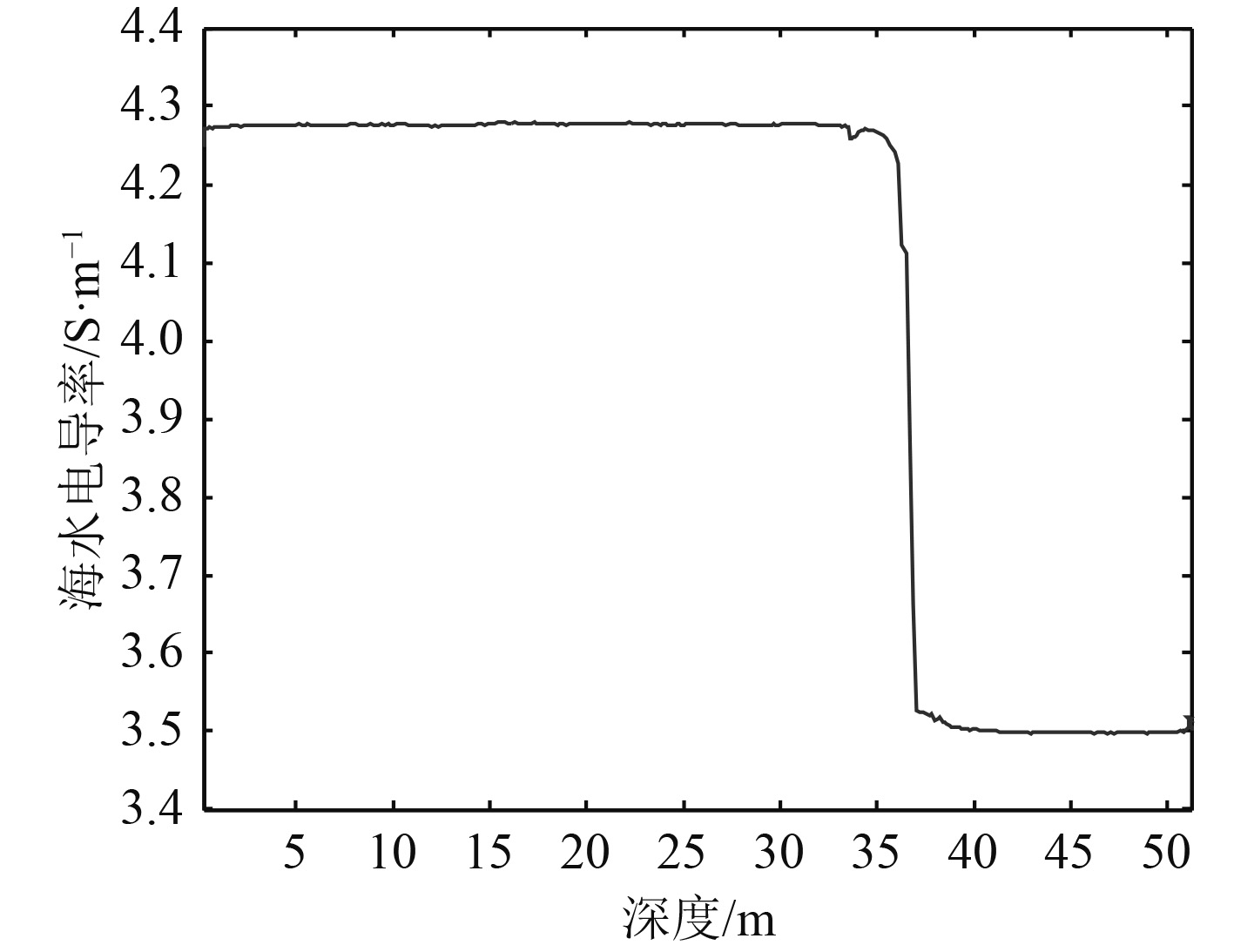
海水电导率受海水温度和盐度的影响而变化。通过测量海水不同深度下的海水电导率,建立等效的海水分层模型。根据某海域海水电导率垂直剖面实测曲线,建立空气—3层海水—海床5层海洋环境模型,其中将海水分为3层,各层深度及电导率数据如表1所示。场源强度为1 A·m,深度为4 m,频率为1 Hz。通过仿真计算了第1层海水中30 m水深处、第2层海水层中35 m水深处、第3层海水层中40 m水深处以及海水-海床界面51.2 m水深处电场三分量数据。
|
|
表 1 仿真计算模型中各层介质电导率及深度 Tab.1 The conductivity and depth of each layer in the simulation model |
|
图 2 某海域海水电导率随深度变化曲线 Fig. 2 Variation curve of seawater conductivity with depth in the sea area |
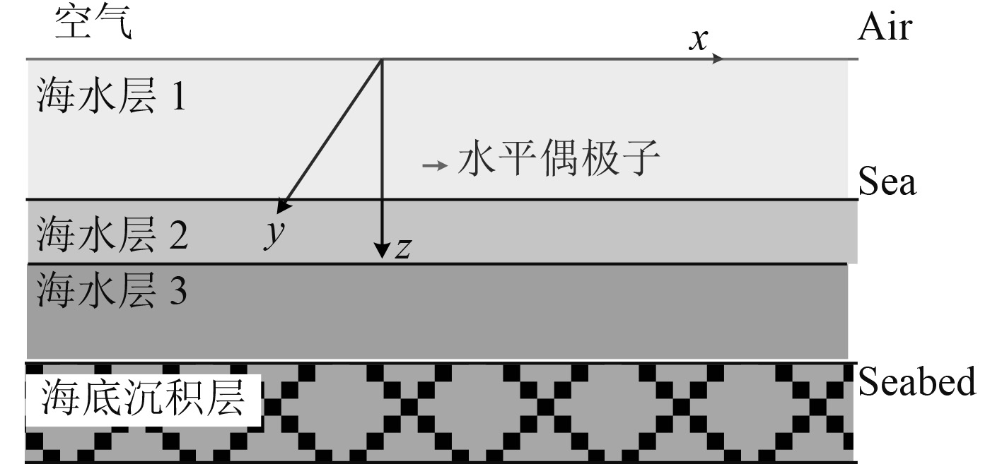
基于上述建立的数学模型,对海水分层条件下时谐水平电偶极子产生的电场进行仿真计算,分析海水分层模型中水下电场的分布特性及衰减规律。模型中取N=5,即模型分为5层:分别为空气-3层海水-海床,模型示意图如图3所示。
|
图 3 5层海洋环境模型中时谐水平电偶极子示意图 Fig. 3 Variation curve of seawater conductivity with depth in the sea area |
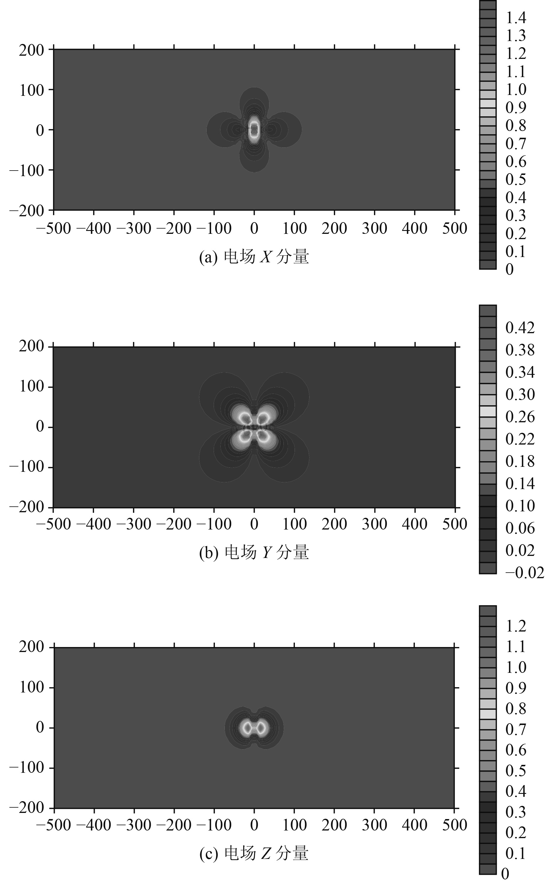
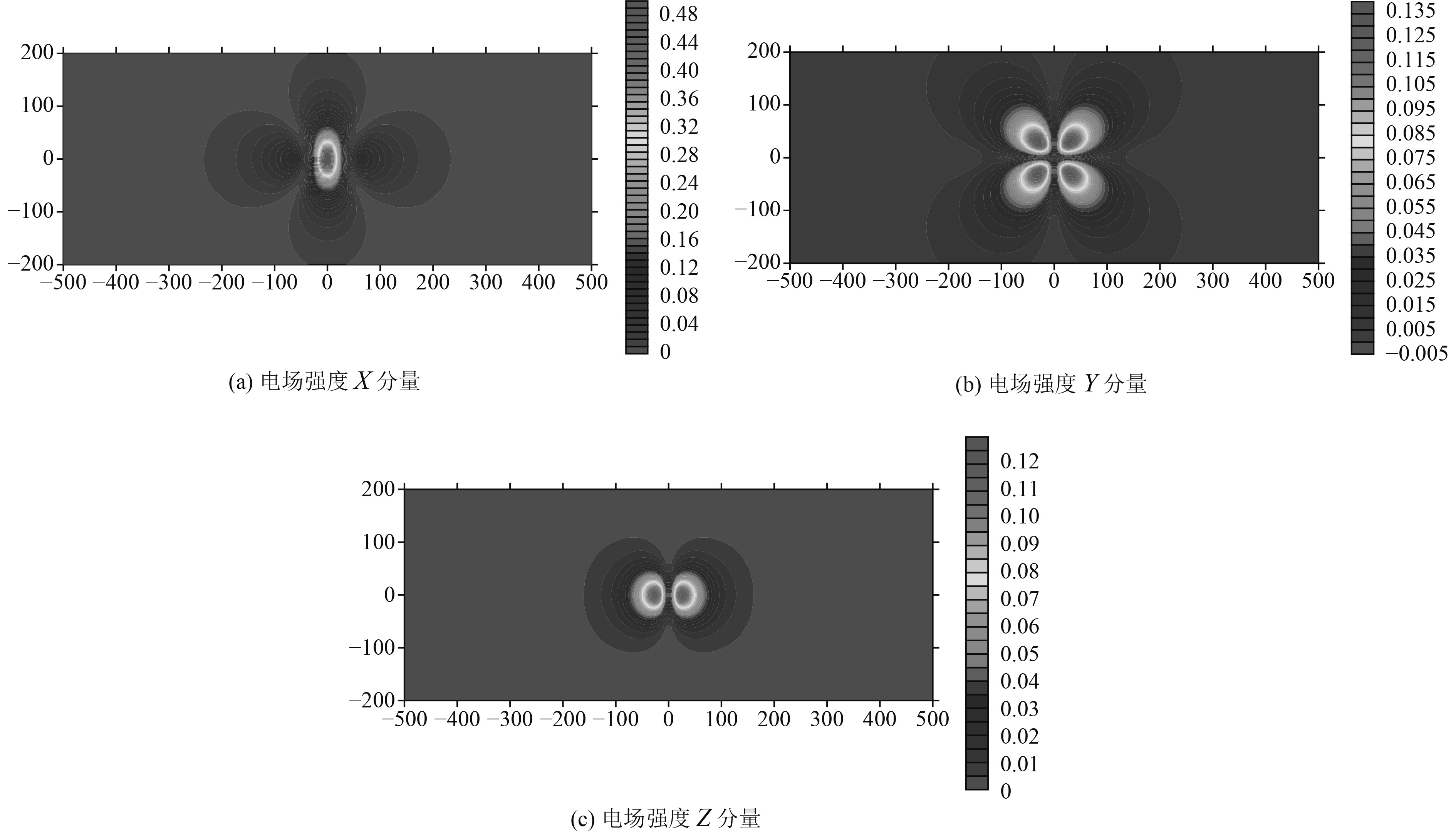
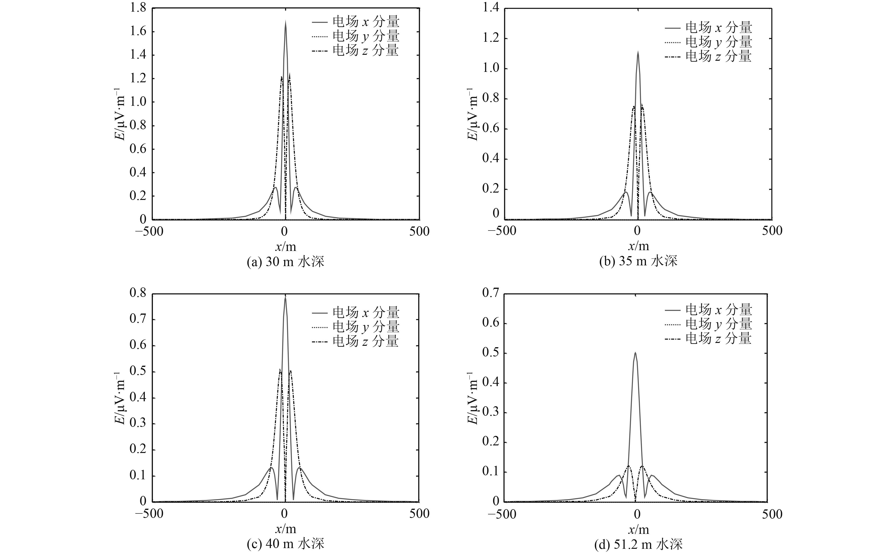
图4~图6给出了场源强度为1 A·m,深度为4 m,频率为1 Hz情况下,偶极子电场在30~51.2 m水深的空间分布及正下方Y=0测线上的分布特性。表2给出了电场特征值统计结果。
|
图 4 电场30 m水深处平面分布等值线图 Fig. 4 Contour map of plane distribution of electric field at the depth of 30 m |
|
图 5 电场51.2 m水深处(海床)平面分布等值线图 Fig. 5 Contour map of plane distribution of electric field at 51.2 m deep water(the seabed) |

|
图 6 偶极子电场三分量空间分布等值线图(30~51.2 m水深) Fig. 6 Contour map of three-component spatial distribution of dipole electric field(30~51.2 m water depth) |
|
|
表 2 电场特征值统计表 Tab.2 Statistical table of electric field characteristic values |
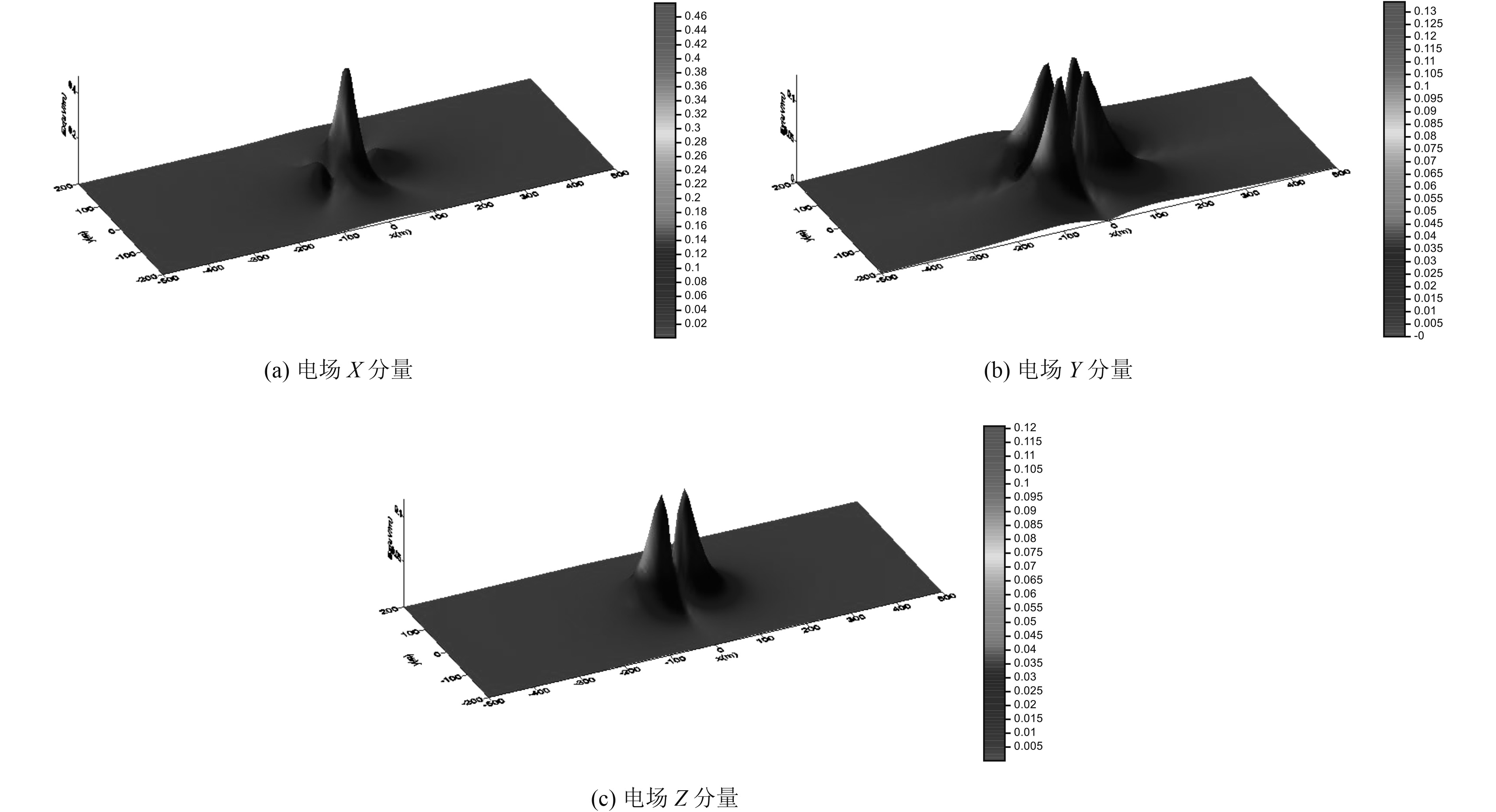
图7给出了电场在海水—海床平面的分布图。图中纵坐标表示X方向,横坐标则表示Y方向。由图可知,电场纵向分量在海水—海床平面上呈现负峰—正峰—负峰特性,整体沿首尾中心线方向对称分布,极大值出现在中部;横向分量沿首尾中心线呈反对称分布,极大值出现在两侧;垂直分量呈正峰—负峰特性,整体沿首尾中心线方向对称分布,极值分别出现在偏离中心的前部和后部。通过上述分析可知,水平电偶极子电场具有较为明显的指向性分布特性。
|
图 7 海床平面上电场分布图(水深51.2 m) Fig. 7 Distribution of electric field on the seabed(water depth: 51.2 m) |
从图8可以看出,随着深度的增加,电场X分量与电场Z分量之比是增加的,这是由于随着深度的增加,海床电导率的影响越来越大。从表2可以看出,在海床界面上,电场Z分量约为电场X分量的1/4。从表中可以看出,电场X分量与电场Z分量都是Y=0处测线最大值(即平面上最大值),电场Y分量最大值相对正下方有一定的偏移。
|
图 8 正下方(Y=0)测线上电场分布 Fig. 8 The electric field distribution on the measuring line(Y=0)is directly below |
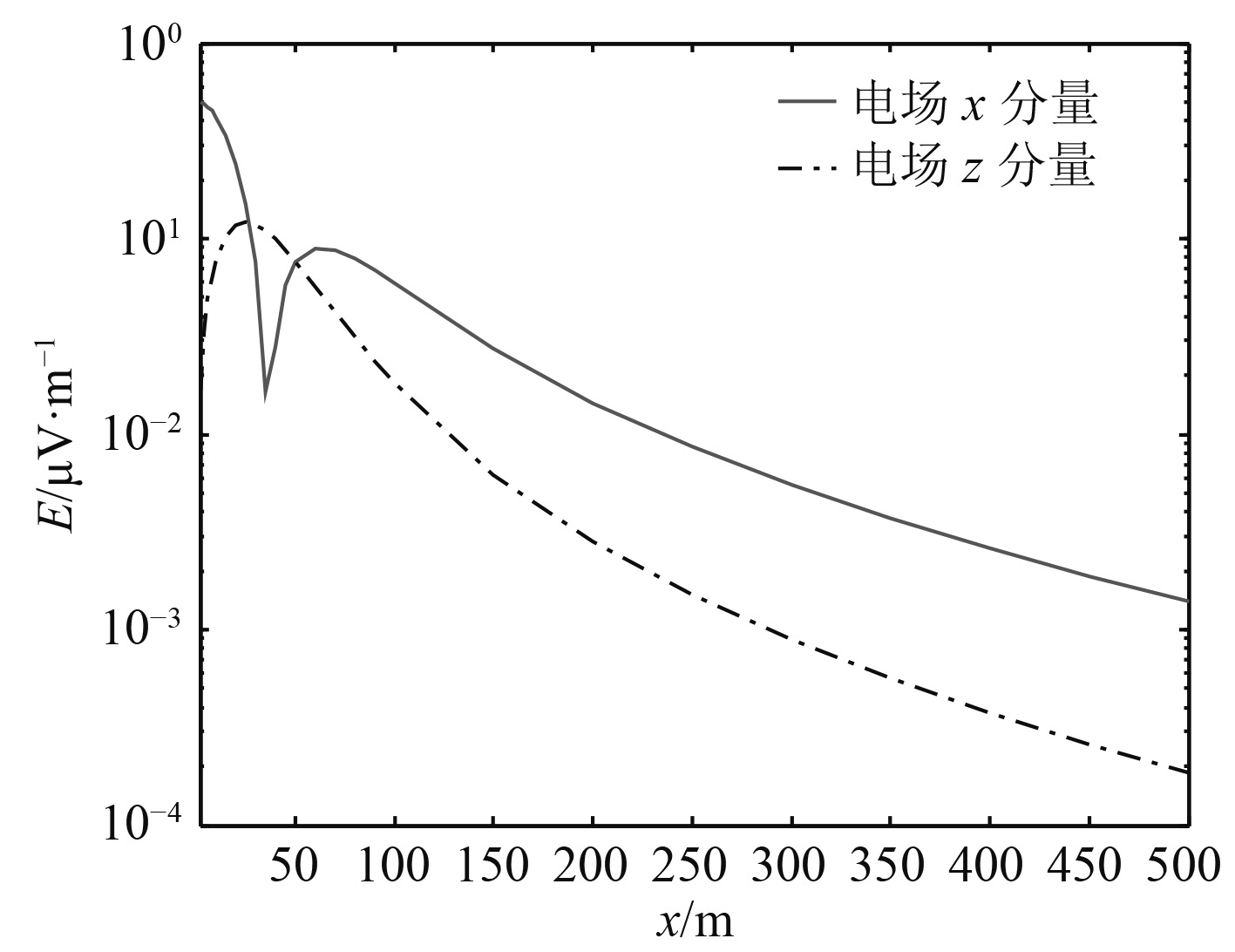
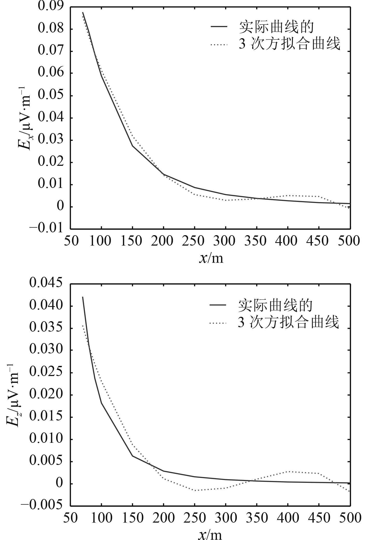
图9和图10给出水深51.2 m,水深4 m,水平电偶极子场源正横Y=0 m,海床电导率为1 S/m,信号频率1 Hz情况下水下电磁场在海水—海床界面的衰减曲线。可以看出,在60~500 m范围内电场X分量和电场Z分量沿径向随距离呈3次方衰减。
|
图 9 电场X分量和电场Z分量在海水—海床界面上沿径向随距离衰减曲线(信号频率1 Hz,海床电导率1 S/m) Fig. 9 Radial and distance attenuation curves of the X component and Z component of the electric field at the sea-seabed interface(Signal frequency 1 Hz,seabed conductivity 1 S/m) |
|
图 10 电场X分量和电场Z分量曲线拟合 Fig. 10 Curve fitting of X component and Z component of electric field |
根据实测海水电导率参数,建立空气—分层海水—海床5层海洋环境模型。通过对海水进一步分层的多层介质模型构建数学模型,进行理论推导和仿真计算,给出场源强度为1 A·m,深度为4 m,频率为1 Hz时电场在不同水深处的空间分布及正下方Y=0测线上的水下电场分布。结果表明,随着水深的增加,电场X分量与电场Z分量之比也随之增大;在海水-海床界面上水平电偶极子电场具有较为明显的指向性分布特性;测线上电场Z分量最大值约为电场X分量最大值的1/4,电场Y分量最大值相对Y=0处有一定的偏移。从衰减曲线可以得知,在60~500 m范围内电场X分量和电场Z分量沿径向随距离呈3次方衰减。
| [1] |
吴云超, 焦达文, 岳瑞永. 海水分层对水平电偶极子产生电场的影响分析[J]. 舰船科学技术, 2020, 6(42): 158-159. WU Yun-chao, JIAO Da-wen, YUE Rui-yong. Analysis of the influence on the electric field of horizontal electric dipole from stratified seawater[J]. Ship Science and Technology, 2020, 6(42): 158-159. |
| [2] |
岳瑞永, 田作喜, 吕俊军, 等. 基于时谐电偶极子模型的舰船轴频电场衰减规律研究[J]. 舰船科学技术, 2009, 31(10): 21-24. YUE Rui-yong, TIAN Zuo-xi, LÜ Jun-jun, et al. Study on attenuation law of the vessel’s shaft rate electric field based on the time-harmonic electric dipole model[J]. Ship Science and Technology, 2009, 31(10): 21-24. DOI:10.3404/j.issn.1672-7649.2009.10.006 |
| [3] |
DAVIDSON S. J., RAWLINS P. G., A multi-influence range with electromagnetic modelling[Z]. Marelec2006, Amsterdam, Netherlands, 2006.
|
| [4] |
LØSETH L. O., URSIN B. Electromagnetic fields in planarly layered anisotropic media[J]. Geophys. J. Int. 2007, 170, 44–80.
|
| [5] |
PERATTA A. B., BAYNHAM J. M. W., ROBERT A. Adey, Advances in cathodic protection modelling of deep well casings in multi-layered media. [C]//Corrosion 2009, Atlanta, Georgia. NACE International, 2009.
|
 2021, Vol. 43
