2. 海军工程大学 电子工程学院,湖北 武汉 430033
2. College of Electronic Engineering, Naval University of Engineering, Wuhan 430033, China
摆弹机是大口径舰炮自动供弹系统的重要组成部分,其作用是将扬弹末端垂直摆放的弹药快速、准确地摆送至转弹机工作位置。摆弹和转弹的交接误差是进行自动供弹系统可靠性研究的必要条件,研究摆弹机运动特性对改进自动机设计,提高机构可靠性对提升装备性能有着重要意义。国内已有学者对满足现代化海战要求的含摆弹机构的舰炮自动供弹系统展开了研究[1-12]。在常见的摆弹机构研究中,普遍基于有限元法和虚拟样机技术。文献[6-7]采用笛卡尔坐标分量和弧坐标分量来共同描述柔性摆弹臂的弹性变形及运动关系;文献[9]考虑摆弹臂的柔性变形及参数的随机分布,以有限元模型为基础,综合运用支持向量回归机与蒙特卡洛法分析动作可靠性;文献[10]建立了考虑弹药质量、质心位置等为随即变量的摆弹机构数学模型;唐文献等[13]应用Ansys软件的FE-SAFE疲劳分析模块,探讨了零件表面粗糙度对中腹摆弹臂的疲劳寿命及安全系数的影响;李渊明[14]运用含间隙机构的分析方法,对摆弹机构进行了运动学和动力学特性分析,并以此对机构的关键部件进行了静力分析和结构改进。
在上述研究的基础上,本文对刚性摆弹机构建立了摆弹机摆弹过程受力模型和运动方程,利用Matlab数值分析,分别对比研究弹药质量偏差±0.2 kg、弹体不同滑移加速度0.1 mm/s2和0.2 mm/s2、以及不同附加转矩1 N/m×sinθ和2 N/m×sinθ时摆弹过程中机构的运动特性变化情况。
1 摆弹机工作机理与受力分析 1.1 摆弹机结构和工作过程摆弹机构主要由动力原件、齿轮齿条组件、摆弹臂3部分组成,如图1所示。其中齿轮轴受支承转动约束,且摆弹臂与齿轮轴固定约束,抱弹装置与摆弹臂相连。摆弹机构在竖直位置时抱弹装置抱住扬弹末端的弹药,动力源对齿条施加拉力,齿条开始向后运动,啮合齿轮逆时针转动并带动摆弹臂摆动,使得摆弹臂上的弹药运动到转弹机交接位置。

|
图 1 摆弹机结构图 Fig. 1 The structure diagram of shell swinging service mechanism |
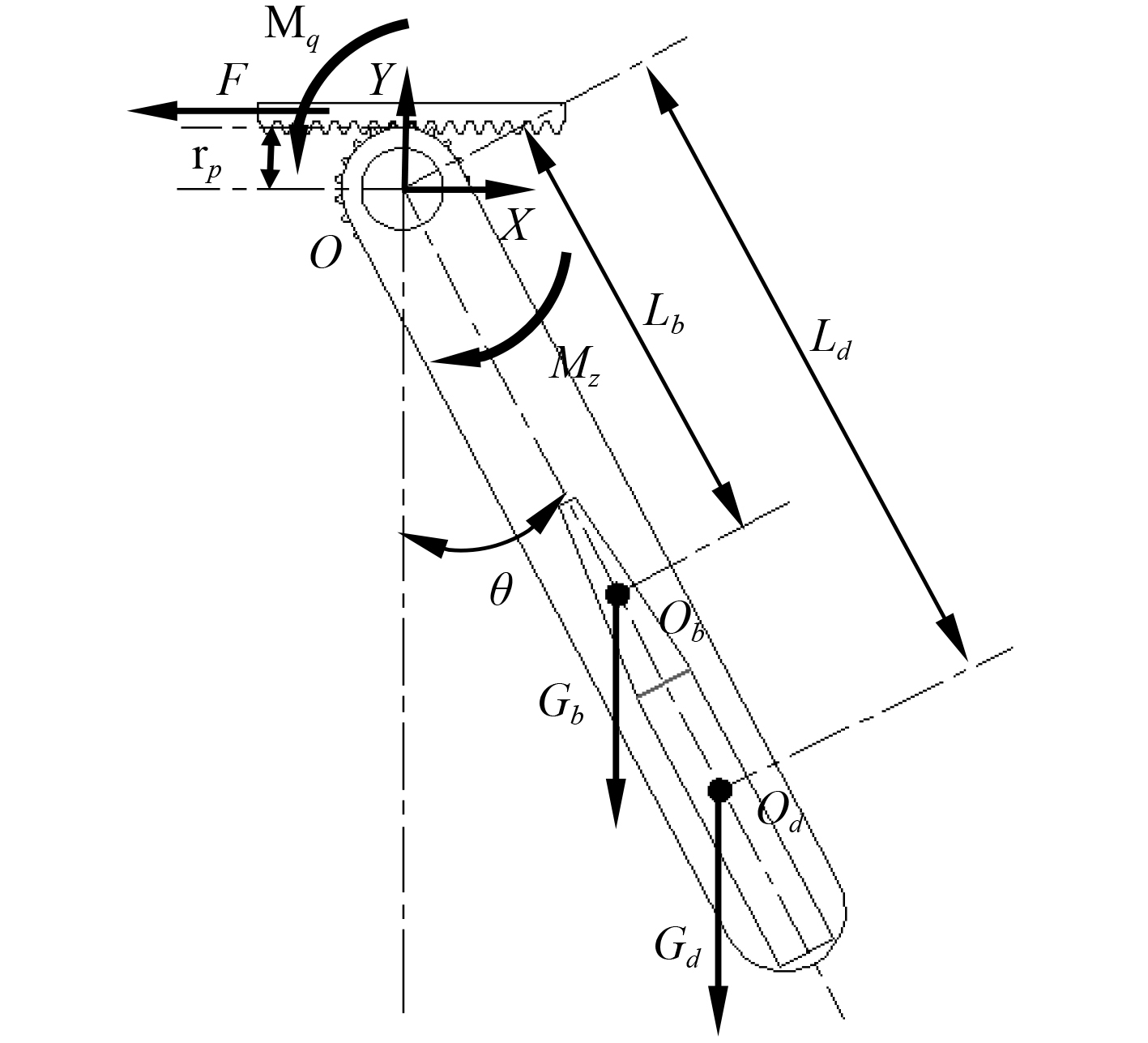
摆弹机摆动过程的受力模型如图2所示。图中O,Ob,Od分别是齿轮转轴轴心,摆臂与抱弹装置的质心,弹体质心;Gb,Gd为

|
图 2 摆弹机受力图 Fig. 2 The force diagram of the shell swinging service mechanism |
弹体在摆弹运动过程中受力如图3所示。图中FN是重力作用下的抱弹装置给的支撑力,Fj是抱弹装置给弹体的紧箍力。

|
图 3 弹体的受力图 Fig. 3 The force diagram of the projectile body |
由图2可知,齿条给齿轮轴心逆时针方向的驱动转矩Mq,摆弹臂和弹体等给齿轮轴心顺时针方向的负载转矩Mz;mt,ml,mb,md分别表示齿条的质量、齿轮与齿轮轴组的质量、摆臂与抱弹装置的质量、弹体的质量;
| $ {\mathrm{x}=r}_{p}\cdot \theta \text{,} $ | (1) |
| $ {{M}}_{\mathrm{q}}=\left(\mathrm{F}-{\mathrm{m}}_{t}\ddot{\mathrm{x}}\right){\mathrm{r}}_{\mathrm{p}}\text{,} $ | (2) |
| $ {J}\ddot{\theta }={{M}}_{\mathrm{q}}-{{M}}_{\mathrm{z}}\text{,} $ | (3) |
| $ {{M}}_{\mathrm{q}}={F}\cdot {{r}}_{\mathrm{p}}-{{m}}_{t}{r}_{p}^{2}\ddot{\theta }\text{,} $ |
| $ {{M}}_{\mathrm{z}}=\left({{G}}_{\mathrm{b}}\cdot {{L}}_{\mathrm{b}}+{{G}}_{\mathrm{d}}{{L}}_{\mathrm{d}}\right)\mathrm{s}\mathrm{i}\mathrm{n}\theta \text{,} $ |
| $ {J}={{J}_{l}+{J}_{b}+{J}_{d}+m}_{b}{L}_{b}^{2}+{m}_{d}{L}_{d}^{2} \text{,}$ |
| $ \left({J}+{{m}}_{t}\cdot {r}_{p}^{2}\right)\ddot{\theta }={F}\cdot {{r}}_{\mathrm{p}}-\left({{G}}_{\mathrm{b}}{{L}}_{\mathrm{b}}+{{G}}_{\mathrm{d}}{{L}}_{\mathrm{d}}\right)\mathrm{s}\mathrm{i}\mathrm{n}\theta \text{,} $ |
| $ \ddot{\theta }=\frac{{F}\cdot {{r}}_{\mathrm{p}}}{{J}+{{m}}_{t}{r}_{p}^{2}}-\frac{\left({{G}}_{\mathrm{b}}{{L}}_{\mathrm{b}}+{{G}}_{\mathrm{d}}{{L}}_{\mathrm{d}}\right)}{{J}+{{m}}_{t}{r}_{p}^{2}}\cdot \mathrm{s}\mathrm{i}\mathrm{n}\theta\text{,} $ | (4) |
| $ {\theta }_{0}{=\theta |}_{t={t}_{0}}=0\text{,}\ddot{{\theta }_{0}}{=\ddot{\theta }|}_{t={t}_{0}}=\frac{{F}\cdot {{r}}_{\mathrm{p}}}{{J}+{{m}}_{t}{r}_{p}^{2}}\text{,} $ |
| $ \int \ddot{\theta }{\rm d}\theta =\int \left(\frac{{F}\cdot {{r}}_{\mathrm{p}}}{{J}+{{m}}_{t}{r}_{p}^{2}}-\frac{\left({{G}}_{\mathrm{b}}{{L}}_{\mathrm{b}}+{{G}}_{\mathrm{d}}{{L}}_{\mathrm{d}}\right)}{{J}+{{m}}_{t}{r}_{p}^{2}}\mathrm{s}\mathrm{i}\mathrm{n}\theta \right){\rm d}\theta \text{,} $ |
| $ \int \dot{\theta }{\rm d}\dot{\theta }=\int \left(\frac{{F}\cdot {{r}}_{\mathrm{p}}}{{J}+{{m}}_{t}{r}_{p}^{2}}-\frac{\left({{G}}_{\mathrm{b}}{{L}}_{\mathrm{b}}+{{G}}_{\mathrm{d}}{{L}}_{\mathrm{d}}\right)}{{J}+{{m}}_{t}{r}_{p}^{2}}\mathrm{s}\mathrm{i}\mathrm{n}\theta \right){\rm d}\theta\text{,} $ |
| $ \frac{{\dot{\theta }}^{2}}{2}=\frac{{F}\cdot {{r}}_{\mathrm{p}}}{{J}+{{m}}_{t}{r}_{p}^{2}}\theta +\frac{\left({{G}}_{\mathrm{b}}{{L}}_{\mathrm{b}}+{{G}}_{\mathrm{d}}{{L}}_{\mathrm{d}}\right)}{{J}+{{m}}_{t}{r}_{p}^{2}}\mathrm{c}\mathrm{o}\mathrm{s}\theta +{C}_{1}\text{,} $ |
| $ \dot{\theta }=\sqrt{\frac{2\cdot {F}\cdot {{r}}_{\mathrm{p}}}{{J}+{{m}}_{t}{r}_{p}^{2}}\cdot \theta +\frac{2\left({{G}}_{\mathrm{b}}{{L}}_{\mathrm{b}}+{{G}}_{\mathrm{d}}{{L}}_{\mathrm{d}}\right)}{{J}+{{m}}_{t}{r}_{p}^{2}}\mathrm{c}\mathrm{o}\mathrm{s}\theta +{C}_{2}}\text{,} $ |
| $ \dot{{\theta }_{0}}=\dot{\theta }{|}_{t={t}_{0}}=0 \text{,}$ |
| $ {C}_{2}=-\frac{2\left({{G}}_{\mathrm{b}}{{L}}_{\mathrm{b}}+{{G}}_{\mathrm{d}}{{L}}_{\mathrm{d}}\right)}{{J}+{{m}}_{t}{r}_{p}^{2}}\text{,} $ |
| $ \dot{\theta }=\sqrt{\frac{2{F}\cdot {{r}}_{\mathrm{p}}}{{J}+{{m}}_{t}{r}_{p}^{2}}\theta \!+\!\frac{2\left({{G}}_{\mathrm{b}}\cdot {{L}}_{\mathrm{b}}+{{G}}_{\mathrm{d}}{{L}}_{\mathrm{d}}\right)}{{J}+{{m}}_{t}{r}_{p}^{2}}\mathrm{c}\mathrm{o}\mathrm{s}\theta \!-\!\frac{2\left({{G}}_{\mathrm{b}}{{L}}_{\mathrm{b}}+{{G}}_{\mathrm{d}}{{L}}_{\mathrm{d}}\right)}{{J}+{{m}}_{t}{r}_{p}^{2}}}{\text{,}}$ | (5) |
| $ \text{令}{A}=\dfrac{2{F}\cdot {{r}}_{\mathrm{p}}}{{J}+{{m}}_{t}{r}_{p}^{2}}\text{,}{B}=\dfrac{2\left({{G}}_{\mathrm{b}}\cdot {{L}}_{\mathrm{b}}+{{G}}_{\mathrm{d}}{{L}}_{\mathrm{d}}\right)}{{J}+{{m}}_{t}{r}_{p}^{2}}\text{,}$ |
| $ \text{则}\ddot{\theta }={A}-{B}\cdot \mathrm{s}\mathrm{i}\mathrm{n}\theta \text{,}$ |
| $ \dot{\theta }=\sqrt{2{A}\cdot \theta +2{B}\mathrm{c}\mathrm{o}\mathrm{s}\theta -2B} \text{,} $ |
| $ {t}_{n}={n}\cdot \Delta {t} \text{,}$ |
| $ \theta {|}_{t={t}_{n}}=\theta {|}_{t={t}_{n-1}}+\dot{\theta }{|}_{t={t}_{n-1}}\cdot \Delta {t} \text{。}$ |
| $ \text{弹体加速度}{a}_{{O}_{d}}=\ddot{\theta }\cdot {L}_{d} \text{,}$ |
| $ \text{弹体速度}{v}_{{O}_{d}}=\dot{\theta }\cdot {L}_{d} \text{,}$ |
| $ \text{弹体位移}{x}_{{O}_{d}}=\theta \cdot {L}_{d} \text{,}$ |
| $ {T}_{1}=\frac{{m}_{b}{v}_{{o}_{d}}^{2}}{2} \text{。}$ |
随着dt和Δt值越小,精度越高,下文求解时dt和Δt均取0.00001。
2.2 考虑弹体滑移时的运动方程实际摆弹过程存在弹体滑移现象,由上式可知,当不考虑碰撞现象,弹体滑移可看成是距离Ld变化对摆弹机构运动特性产生的影响,同时文献[11]考虑的弹药质量参数变化也可以看成是质心位置发生了变化。在摆动过程中将弹体作为对象进行受力分析,由图3可知,弹体受垂直向下的重力Gd,一部分被弹体和抱弹装置间产生的摩擦力Ff抵消,剩余合成力导致弹体滑移。
| $ {{F}}_{{N}}={{G}}_{{d}}\cdot \mathrm{c}\mathrm{o}\mathrm{s}\theta \text{,}$ |
| $ {{F}}_{f}=\mu \cdot \left({{F}}_{{N}}+{{F}}_{{j}}\right) \text{,}$ |
| $ {{m}}_{{d}}\cdot \ddot{{{x}}_{{d}}}={\dot{{\theta }'}}^{2}\cdot {L}_{d}'+{{G}}_{{d}}\mathrm{s}\mathrm{i}\mathrm{n}{\theta }'-{{F}}_{f}\text{,} $ |
| $ \ddot{{{x}}_{\mathrm{d}}}=\frac{{{\dot{{\theta }'}}^{2}\cdot {L}_{d}'+{G}}_{{d}}\mathrm{s}\mathrm{i}\mathrm{n}{\theta }'-\mu \cdot \left({{F}}_{{N}}+{{F}}_{{j}}\right)}{{{m}}_{{d}}} \text{,}$ |
| $ {{x}}_{{d}}{|}_{t={t}_{n}}=\left(\ddot{{{x}}_{\mathrm{d}}{|}_{t={t}_{n-1}}}\cdot \Delta t+\dot{{{x}}_{{d}}}{|}_{t={t}_{n-1}}\right)\Delta {t}+{{x}}_{{d}}{|}_{t={t}_{n-1}}{\text{,}}$ |
| $ {L}_{d}'={L}_{d}+{x}_{{d}}\text{,} $ |
| $\begin{array}{*{20}{l}} \mathop {{{{x}}_{{d}}}}\limits^. \!=\! \left\{ {\frac{{{{\left( {\dot \theta '{|_{t = {t_{n - 1}}}}} \right)}^2} \cdot \left( {{L_d} \!+\! {x_{\rm{d}}}{|_{t = {t_{n - 1}}}}} \right)}}{{{{{m}}_{{d}}}}} \!+\! \frac{{{{{G}}_{{d}}}{\rm{sin}}\left( {\theta '{|_{t = {t_{n - 1}}}}} \right) \!-\! \mu \cdot \left( {{{{F}}_{{N}}} \!+\! {{{F}}_{{j}}}} \right)}}{{{{{m}}_{{d}}}}}} \right\} \cdot \Delta {{t}} \end{array}\text{。}$ |
当
将
| $ \text{弹体加速度}{a}_{{O}_{d}}'=\ddot{{\theta }'}\cdot {L}_{d}' \text{,}$ |
| $ \text{弹体速度}{v}_{{O}_{d}}'=\dot{{\theta }'}\cdot {L}_{d}' \text{,}$ |
| $ \text{弹体位移}{x}_{{O}_{d}}'={\theta }'\cdot {L}_{d}'\text{,}$ |
| $ {T}_{2}=\frac{1}{2}{m}_{b}{{v}'}_{{o}_{d}}^{2} \text{。}$ |
式中:μ为摩擦系数,
参考三维间隙接触模式[15],弹体在含间隙的抱弹装置中滑移时会产生XOY平面的转动,使得摆弹机构附加转矩
| $ {{{M}}_{Z}'={M}}_{{z}}+{{M}}_{{f}}=\left({{G}}_{{b}}\cdot {{L}}_{{b}}+{{G}}_{{d}}{{L}}_{{d}}\right)\mathrm{s}\mathrm{i}\mathrm{n}{\theta '}'+{{M}}_{{f}} \text{,}$ |
| $ {J}\ddot{\theta ''}={{M}}_{{q}}-{{M}}_{Z}' \text{,}$ |
| $ \ddot{\theta ''}=\frac{{F}\cdot {{r}}_{{p}}-\left({{G}}_{{b}}{{L}}_{{b}}+{{G}}_{{d}}{{L}}_{{d}}\right)\mathrm{s}\mathrm{i}\mathrm{n}{\theta '}'-{{M}}_{{f}}}{{{J}_{l}+{J}_{b}+{J}_{d}+m}_{b}{L}_{b}^{2}+{m}_{d}{L}_{d}^{2}+{{m}}_{t}{r}_{p}^{2}} \text{,}$ |
| $ {{\theta '}'}_{0}{=\theta ''|}_{t=0},\ddot{{\theta ''}_{0}}{=\ddot{\theta ''}|}_{t=0}=\frac{{F}\cdot {{r}}_{{p}}-{{M}}_{{f}}}{{J}+{{m}}_{t}{r}_{p}^{2}}\text{,} $ |
| $ \begin{split} &\dot{\theta ''}\!=\\ &\sqrt{\frac{2{F}\!\cdot\! {{r}}_{{p}}\!\!-\!\!2{{M}}_{{f}}}{{J}+{{m}}_{t}\cdot {r}_{p}^{2}}\theta ''\!\!+\!\!\frac{2\left({{G}}_{{b}}\!\cdot\! {{L}}_{{b}}\!\!+\!\!{{G}}_{{d}}{{L}}_{{d}}\right)}{{J}\!\!+\!\!{{m}}_{t}\!\cdot\! {r}_{p}^{2}}\mathrm{c}\mathrm{o}\mathrm{s}\theta \mathrm'\mathrm'\!\!-\!\!\frac{2\left({{G}}_{{b}}{{L}}_{{b}}\!\!+\!\!{{G}}_{{d}}{{L}}_{{d}}\right)}{{J}\!\!+\!\!{{m}}_{t}\cdot {r}_{p}^{2}}}\text{,}\end{split} $ |
| $ \text{弹体加速度}{a}_{{O}_{d}}^{''}=\ddot{\theta ''}\cdot {L}_{d}\text{,}$ |
| $ \text{弹体速度}{v}_{{O}_{d}}^{''}=\dot{\theta ''}\cdot {L}_{d}\text{,}$ |
| $ \text{弹体位移}{x}_{{O}_{d}}^{''}=\theta ''\cdot {L}_{d}\text{,}$ |
| $ {T}_{3}=\frac{{m}_{b}{{v}^{''}}_{{o}_{d}}^{2}}{2}\text{。} $ |
式中,T3为附加转矩
为得到3种状态下的弹体运动特性,分别取F=3288.6×θ+cosθ,mt=10 kg,ml=5 kg,mb=35 kg,md=40 kg,rp=0.1 m,Lb=0.5 m,Ld=0.85 m,Jl=0.025 N/m,Jb=1.45 N/m,Jd=5 N/m,g=10 m/s2。
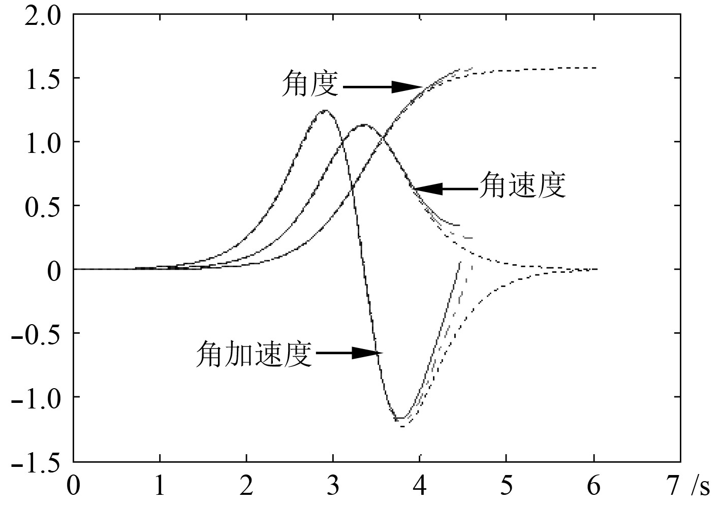
3.1 不同弹体质量偏差时的运动特性在理想运动状态下,取弹体质量变化Δm1=−0.2 kg,Δm2=0 kg,Δm3=0.2 kg,可得到运动特性变化情况如图4所示。图中实线、点画线和虚线分别表示弹体质量变化Δm1=−0.2 kg,Δm2=0 kg,Δm3=0.2 kg时的运动特性曲线。

|
图 4 不同质量偏差下的运动曲线 Fig. 4 The motion curves under different mass deviations |
由图4可知,弹体质量偏差对摆弹运动有较大影响,且弹体质量增加过大,可能导致摆弹动作不到位,造成供弹失败。
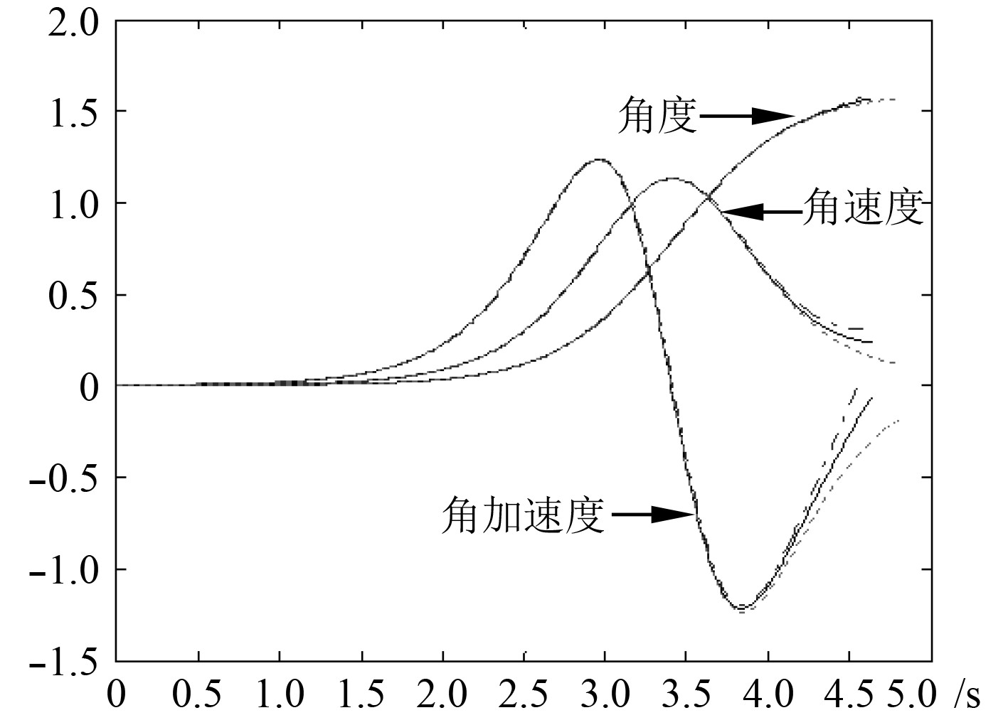
3.2 考虑弹体滑移时的运动特性为得到弹体滑移时摆弹的运动特性,考虑到弹体滑移受转速、预紧力等多因素的影响,研究在给定弹体滑移加速度
由图5可知,弹体滑移会导致摆弹时间变长,随滑移加速度增大而增大。

|
图 5 不同滑移加速度下的运动曲线 Fig. 5 The motion curves under different slip accelerations |
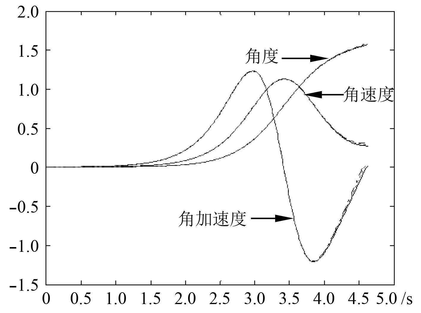
研究弹体含3种不同附加转矩

|
图 6 不同附加转矩下的运动曲线 Fig. 6 The motion curves under different additional torque |
由图6可知,小附加转矩对摆弹机构运动特性影响较小。
4 结 语通过施加上述驱动力对机构进行运动受力分析、方程推导和数值对比,计算得到摆弹机构的运动特性。结果表明:
1)弹体质量偏差对摆弹运动有较大影响,且弹体质量增加过大,可能导致摆弹不到位,造成供弹失败。
2)弹体滑移会导致摆弹时间变长,随滑移加速度增大而增大。
3)当弹体在运动过程中具有小附加转矩时,对摆弹机构运动特性影响较小。
4)在研究各运动参数变化对摆弹机构运动特性影响时,可利用本文公式进行计算分析。但是该公式计算其他形式摆弹机构时的精度有待于实验的进一步验证。
| [1] |
张相炎, 郑建国, 杨军荣. 火炮设计理论[M]. 北京: 北京理工大学, 2014.
|
| [2] |
程刚, 张相炎, 董志强. 供弹动作可靠性仿真研究[J]. 海军工程大学学报, 2011, 23(2): 72-75. CHENG Gang, ZHANG Xiang-yan, DONG Zhi-qiang. Motion reliability simulation research on feed mechanism[J]. Journal of naval university of engineering, 2011, 23(2): 72-75. DOI:10.3969/j.issn.1009-3486.2011.02.015 |
| [3] |
程刚, 张相炎, 董志强, 等. 偏离运动仿真在供弹机构故障分析和优化设计中的应用[J]. 火炮发射与控制学报, 2010(01): 64-66. CHENG Gang, ZHANG Xiang-yan, DONG Zhi-qiang, et al. Application of bias motion simulation in fault analysis and optimal design of feed mechanism[J]. Journal of artillery launch and control, 2010(01): 64-66. DOI:10.3969/j.issn.1673-6524.2010.01.016 |
| [4] |
程刚. 高射频自动机及供输弹机构动态特性研究[D]. 南京: 南京理工大学, 2011. CHENG Gang. Dynamic character research of high-speed- fire automatic gun and feed mechanism[D]. Nanjing university of science and technology, 2011. |
| [5] |
杨丽. 自动火炮供弹机可靠性及关键性能评估策略研究[D]. 沈阳: 东北大学, 2015. YANG Li. Research on reliability and assessment strategy of key performance for automatic canon feed mechanism[D]. Northeastern University, 2015. |
| [6] |
胡胜海, 古青波, 彭浩宸, 等. 中腹摆弹机构刚—柔耦合建模及摆弹误差分析[J]. 南京理工大学学报, 2013, 37(03): 398-403. HU Sheng-hai, GU Qing-bo, PENG Hao-chen, et al. Rigid-flexible coupling modeling of abdominal shell- swinging mechanism and shell-swinging error analysis[J]. Journal of nanjing university of science and technology, 2013, 37(03): 398-403. |
| [7] |
胡胜海, 古青波, 彭浩宸, 等. 中腹摆弹臂的递归学习输入成形振动抑制方法[J]. 北京理工大学学报, 2013, 33(11): 1107-1112+1118. HU Sheng-hai, GU Qing-bo, PENG Hao-chen, et al. Iterative learning input shaping vibration suppression method for the abdominal shell-swing arm[J]. Journal of Beijing institute of technology, 2013, 33(11): 1107-1112+1118. DOI:10.3969/j.issn.1001-0645.2013.11.002 |
| [8] |
古青波, 彭浩宸, 叶小红, 等. 考虑摆弹臂柔性的中腹摆弹机构动力特性分析[J]. 应用科技, 2013, 40(1): 30-34. GU Qing-bo, PENG Hao-chen, YE Xiao-hong, et al. Dynamic characteristics analysis of the abdominal shell-swinging mechanism considering the shell-swinging arm flexible[J]. Applied Science and Technology, 2013, 40(1): 30-34. |
| [9] |
可学为, 侯健, 陈汀峰. 考虑摆臂柔性的舰炮摆弹机构动作可靠性及灵敏度分析[J]. 海军工程大学学报, 2014(4): 101-104. KE Xue-wei, HOU Jian, CHENG Ting-feng. Analysis of action reliability and sensitivity of naval gun ammunition swing device in view of flexible swing arm[J]. Journal of naval university of engineering, 2014(4): 101-104. |
| [10] |
侯健, 可学为, 魏平, 等. 大口径舰炮摆弹机构的动态设计[J]. 自然科学版, 2010, 34(4): 528-532. HOU Jian, KE Xue-wei, WEI Ping, et al. Dynamic design for ammunition swing device of large caliber ship gun[J]. Journal of nanjing university of science and technology (natural science edition), 2010, 34(4): 528-532. |
| [11] |
可学为, 侯健, 陈汀峰, 等. 大口径舰炮摆弹机构的动作可靠性分析[J]. 计算机仿真, 2013, 30(12): 5-8. KE Xue-wei, HOU Jian, CHENG Ting-feng, et al. Search on action reliability for ammunition swing device of large caliber ship gun[J]. Computer simulation, 2013, 30(12): 5-8. DOI:10.3969/j.issn.1006-9348.2013.12.002 |
| [12] |
侯健, 樊龙龙, 可学为. 基于ADAMS和MATLAB的大口径舰炮发射系统动力学仿真[J]. 海军工程大学学报, 2009, 21(06): 62-65. HOU Jian, FAN Long-long. KE Xue-wei. Dynamic simulation of coupling firing for major caliber naval gun based on ADAMS and Matlab[J]. Journal of naval university of engineering, 2009, 21(06): 62-65. |
| [13] |
唐文献, 张丽娟, 郭晓冬, 等. 中腹摆弹机摆臂疲劳特性研究[J]. 自然科学版, 2015, 29(5): 474-479. TANG Wen-xian, ZHANG Li-jian, GUO Xiao-dong, et al. Fatigue analysis of the swing arm of mid-bilge shell-feeding device[J]. Journal of Jiangsu University of Science and Technology (Natural Science Edition), 2015, 29(5): 474-479. |
| [14] |
李渊明. 大口径舰炮供弹系统摆弹机构动力学特性研究[D]. 哈尔滨: 哈尔滨工程大学, 2017. LI Yuan-ming. Research on dynamic characteristics of ammunition-swing mechanism in the ammunition feeding system of the large caliber naval gun[D]. Harbin Engineering University, 2017. |
| [15] |
YAN S, XIANG W, LIN Z. A comprehensive model for 3D revolute joints with clearances in mechanical systems[J]. Nonlinear Dynamics, 2015, 80(1-2): 309-328. DOI:10.1007/s11071-014-1870-7 |
 2020, Vol. 42
