推进系统是船舶的主动脉,是主机实现动力传递的关键部分,对船舶航行的可靠性和经济性起着决定性的作用。当船舶采用柴-柴联合(CODAD)推进系统时,可以有效地拓宽主机功率覆盖范围,在动力性和经济性方面具有十分显著的优势,但同时也存在瞬态性能较差、易导致怠速空转情况下突然接排正车或倒车离合器而失速停车的问题,严重时还有可能出现增压器喘振等故障现象。在船舶推进系统及其控制系统的设计阶段,必须考虑柴油机上述问题对整个推进系统动态特性的影响[1]。
船舶推进系统是一个复杂的非线性系统,无法用常规的分析方法计算其各工况下的动态特性,而借助于陆上联调和海上实船试验耗时长、投资多、风险大,且受到各种条件的限制。随着计算机仿真技术在能源、动力领域内的应用及发展,其应用于船舶推进系统的相关研究逐渐显示出独特的优越性,且仿真结果可以为后续研制阶段提供技术支撑,为台架试验和陆上联调等提供参考和指导。因此,开展推进系统动态特性仿真研究十分必要[2]。
1 推进系统数学模型 1.1 柴油机将柴油机动力装置简化成由2个旋转质量(柴油机和负载)和1个无惯性的联接轴所组成的当量系统,则柴油机的动力学方程为[3]:
| $ \frac{{{\text{π}} {I_e}}}{{30}}\frac{{{\rm d}{N_d}}}{{dt}} = {M_i} - {M_B} - {M_f} {\text{。}} $ | (1) |
式中:
柴油机指示扭矩计算公式为:
| $ {M_i} = {{{H_u}{g_c}{\eta _i}} / {\tau{\text{π}} }} {\text{,}} $ | (2) |
| $ {M_e} = {M_i} \cdot {\eta _m} {\text{。}} $ | (3) |
式中:
柴油机指示效率
| $ {\eta _i} = ({C_1} + {C_2}{N_d} - {C_3}N_d^3)(1 - {C_4}{\alpha ^{ - {C_5}}}) {\text{,}} $ | (4) |
式中:
柴油机机械效率计算公式为:
| $ {\eta _m} = \frac{{{p_e}}}{{{p_i}}} = \frac{{{p_e}}}{{{p_e} + {p_m}}} {\text{。}} $ | (5) |
式中:
从运动传递角度来看,减速齿轮箱模型可用转速的减速比
| $ {N_d} = {N_p} \cdot i {\text{,}} $ | (6) |
| $ {Q_d} = {Q_p} \cdot i {\text{,}} $ | (7) |
| $ {I_d} = {I_p} \cdot i {\text{。}} $ | (8) |
式中,
设同一机组的各部件性能参数基本一致,则桨轴动力学方程为:
| $ {M_e} \cdot i \cdot T \cdot {\eta _{gb}} - {M_{f2}} - {M_p} = {I_s} \cdot \frac{{\text{π}} }{{30}} \cdot \frac{{{\text{d}}{N_p}}}{{{\text{d}}t}} {\text{。}} $ | (9) |
式中:
轴系摩擦损失扭矩
| $ {M_{f2}} = \left( {\frac{1}{3} + \frac{2}{3} \cdot \frac{{{N_p}}}{{{N_{d0}}}} \cdot i} \right){M_{fd0}} {\text{。}} $ | (10) |
式中:
轴系当量转动惯量计算公式为:
| $ {I_s} = {I_1} \cdot {i^2} \cdot {\eta _{gb}} + {I_2} + {I_3} {\text{。}} $ | (11) |
式中:
根据螺旋桨的工作原理,螺旋桨轴上产生推力
| $ {T_p} = {K_T}\rho N_p^2{D^4} {\text{,}} $ | (12) |
| $ {M_p} = {K_Q}\rho N_p^2{D^5} {\text{。}} $ | (13) |
式中:
上述是螺旋桨在敞水中的水动力特性,实际上,螺旋桨在工作中会受到船体尾部流场的影响,同时反作用于船体尾部流场,这样就进一步产生了推力减额和伴流现象。螺旋桨有效推力
| $ {T_e} = {T_p}\left( {1 - {t_p}t} \right) {\text{,}} $ | (14) |
| $ {V_p} = {V_s}\left( {1 - w} \right) {\text{。}} $ | (15) |
式中:
螺距系数采用Donnelly公式计算[6]:
| $ {t_p} = \left\{ {\begin{array}{*{20}{c}} 3 {\text{,}}&{P/D \leqslant {\rm{ - 1}}} {\text{,}} \\ { - 3P/D} {\text{,}}&{{\rm{ - 1 < }}P/D{\rm{ < 0}}} {\text{,}} \\ {{\rm{ }}P/D} {\text{,}}&{{\rm{0}} \leqslant {\rm{ }}P/D{\rm{ < 1}}} {\text{,}}\\ 1 {\text{,}}&{P/D \geqslant {\rm{1}}} {\text{。}} \end{array}} \right. $ | (16) |
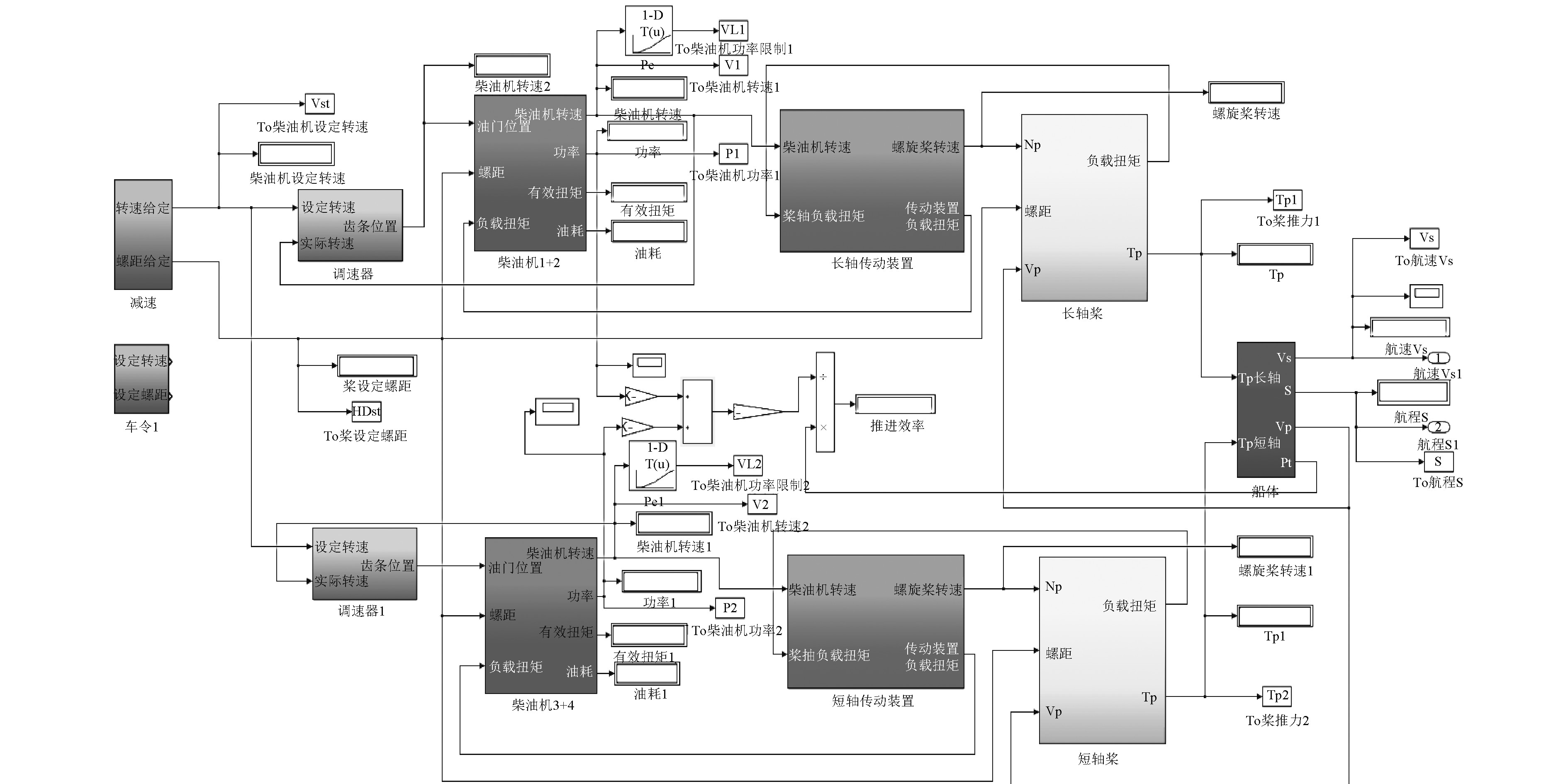
推进系统由4台柴油机、2套并车减速齿轮箱及2套调距桨组成,主要对加、减速以及由全正车到全倒车等动态过程进行仿真研究,其中各个过程的时间控制参数设置如表1所示。依据上述章节中各模块的数学模型,基于Simulink仿真环境建立推进系统仿真模型,如图1所示。
|
|
表 1 动态控制参数 Tab.1 Dynamic control parameters |
|
图 1 推进系统仿真模型 Fig. 1 Propulsion system simulation model |
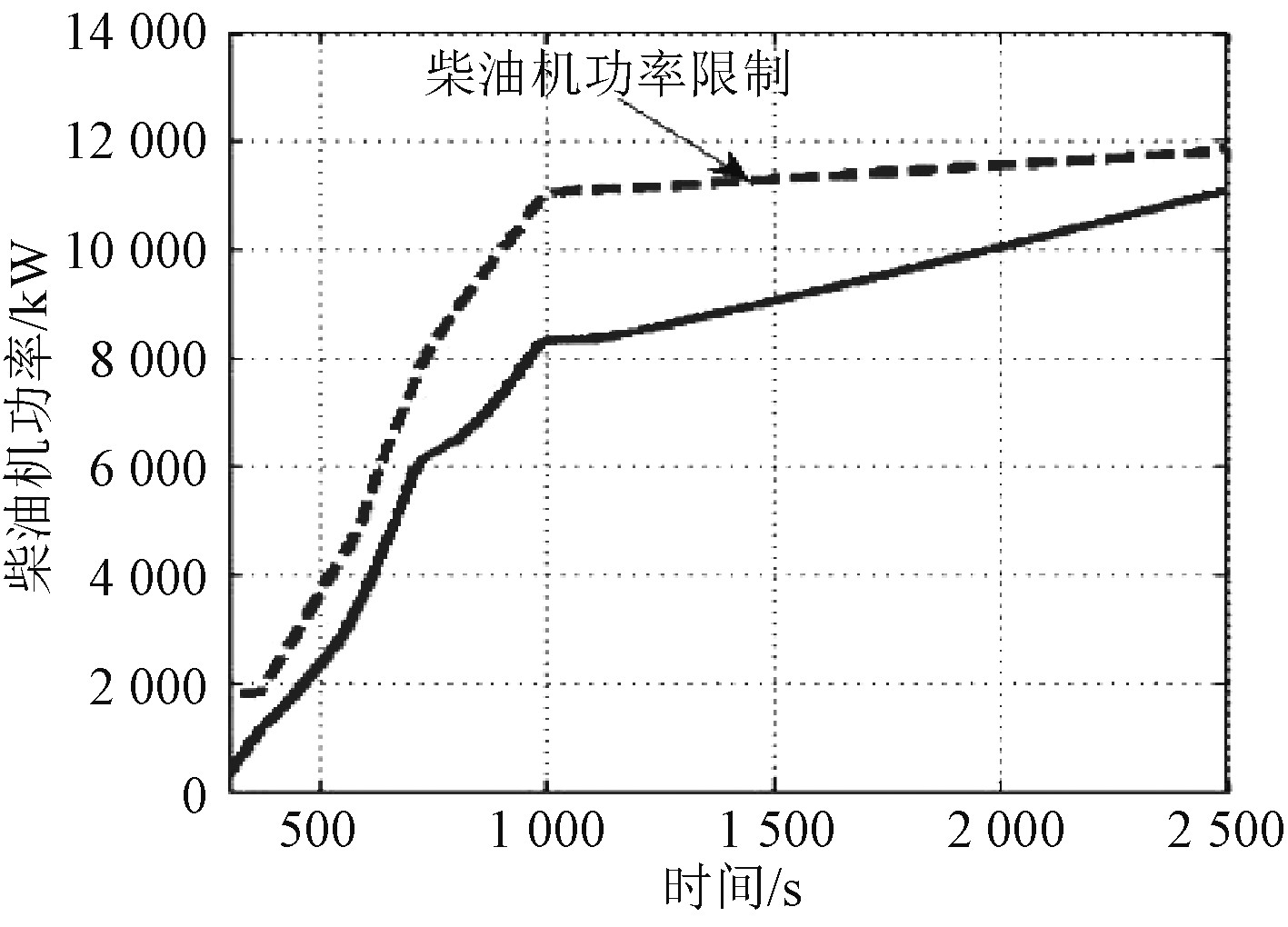
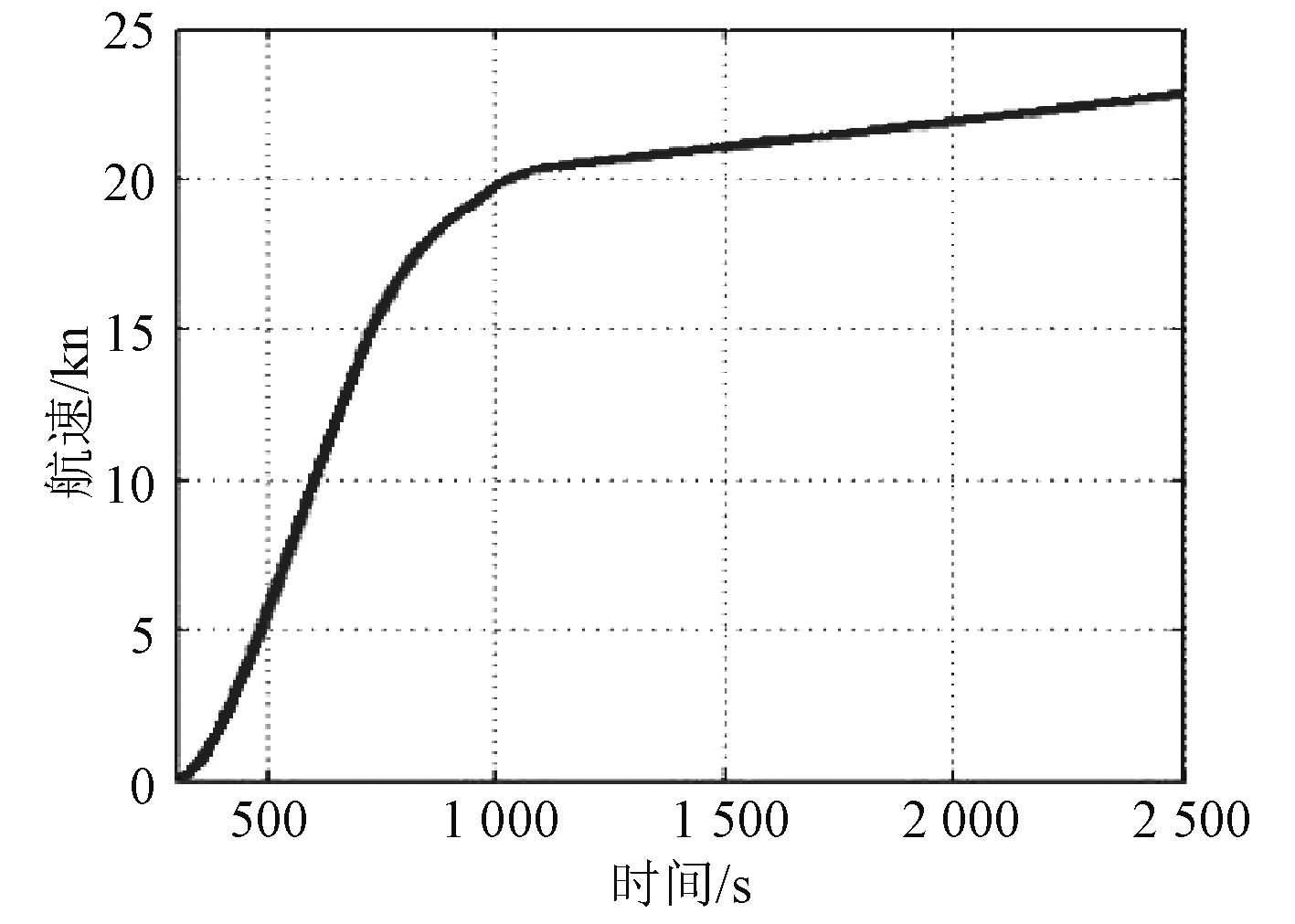
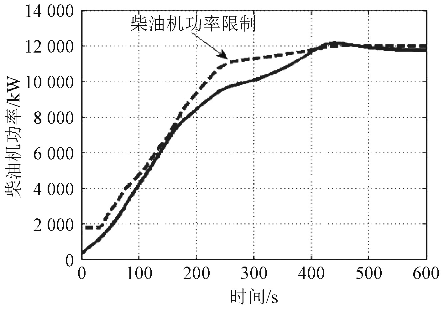
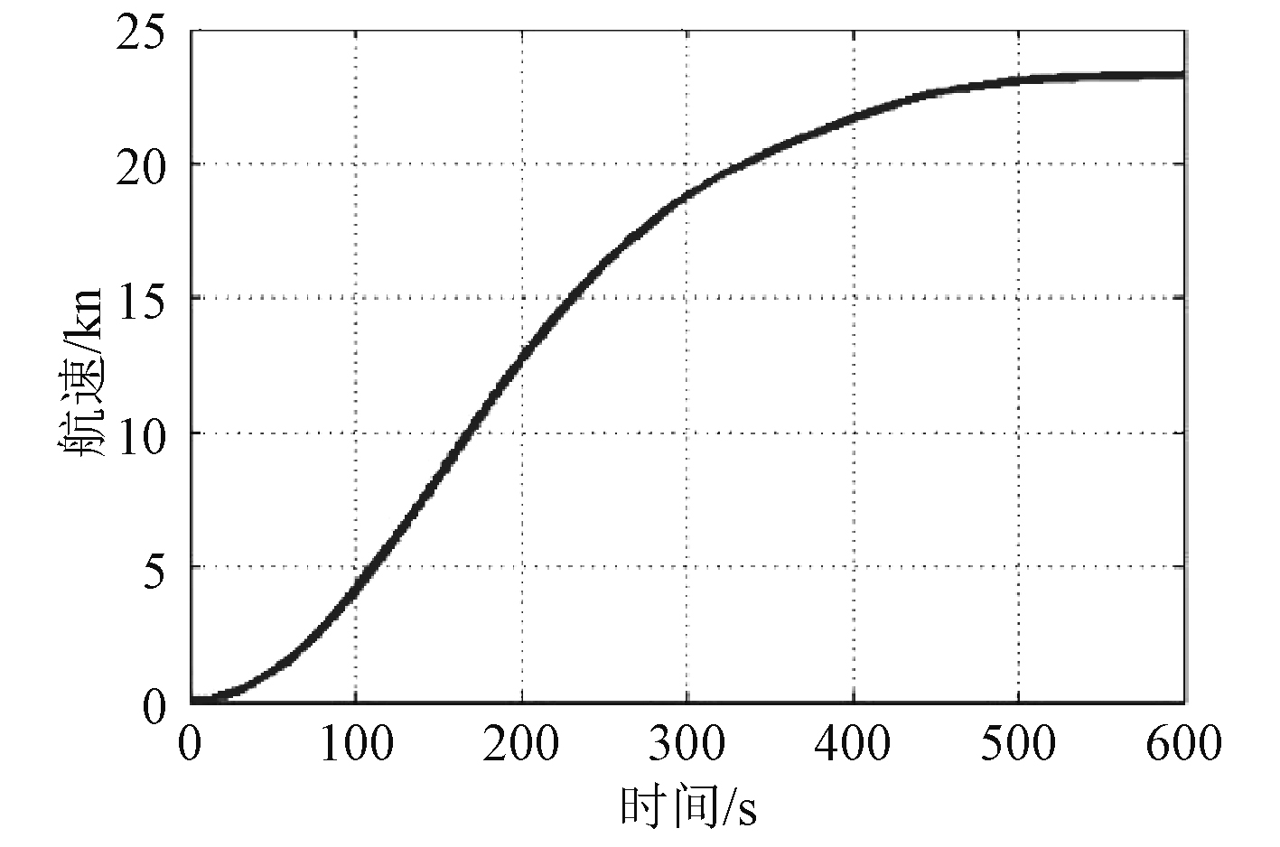
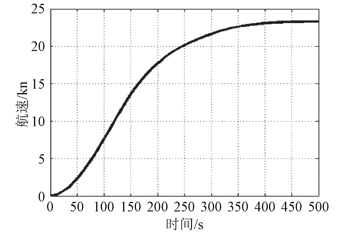
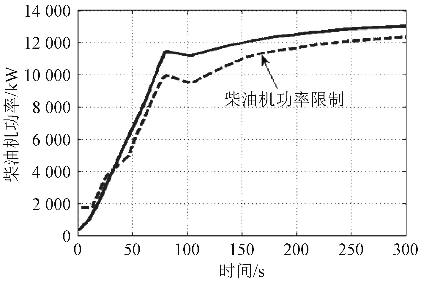
图2~图9为推进系统冷、热机的正常、应急加速过程仿真结果。可以看出,主机在冷机状态下加速比较缓慢,不存在超过柴油机功率限制曲线的情况,运行状况良好;在热机状态下则出现了超过柴油机功率限制曲线的情况,尤其是在应急加速时比较严重。加速过程航速变化总体较为平稳,缓慢增加。这主要是由于推进系统加速度达到最大时,主机功率已达到甚至超过额定功率,螺距比也已达到理论设计最大值,此时存在转速振荡调整过程,加剧了主机功率的变化程度,若加速调节时间没有完全匹配,就极易导致加速过程主机超负荷[7-8]。
|
图 2 冷机正常加速过程主机功率变化规律 Fig. 2 Power variation of main engine during normal acceleration of cooling engine |

|
图 9 热机应急加速过程航速变化规律 Fig. 9 Ship speed variation during emergency acceleration of heat engine |
|
图 3 冷机正常加速过程航速变化规律 Fig. 3 Ship speed variation during normal acceleration of cooling engine |
|
图 4 冷机应急加速过程主机功率变化规律 Fig. 4 Power variation of main engine during emergency acceleration of cooling engine |
|
图 5 冷机应急加速过程航速变化规律 Fig. 5 Ship speed variation during emergency acceleration of cooling engine |

|
图 6 热机正常加速过程主机功率变化规律 Fig. 6 Power variation of main engine during normal acceleration of heat engine |
|
图 7 热机正常加速过程航速变化规律 Fig. 7 Ship speed variation during normal acceleration of heat engine |
|
图 8 热机应急加速过程主机功率变化规律 Fig. 8 Power variation of main engine during emergency acceleration of heat engine |
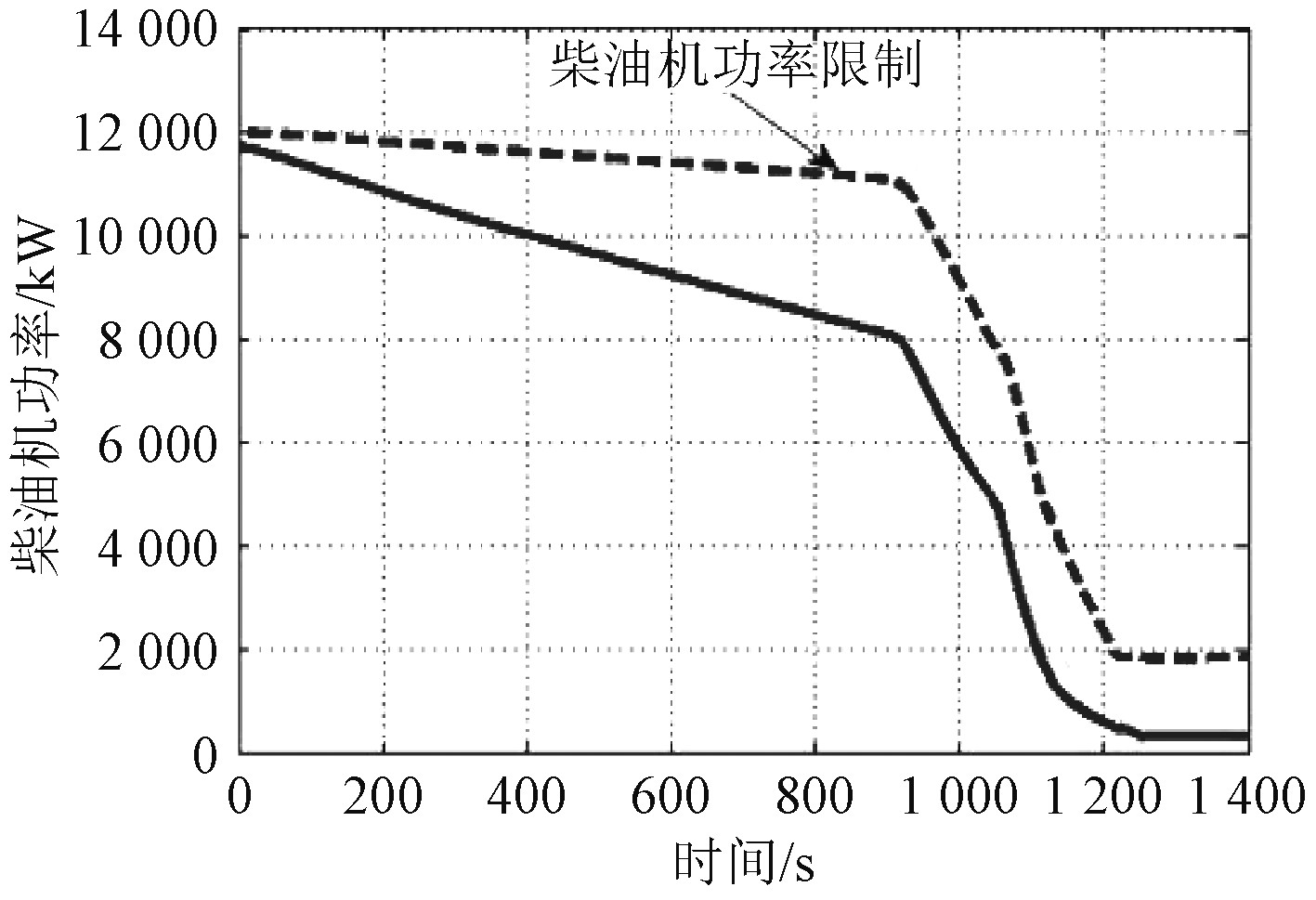
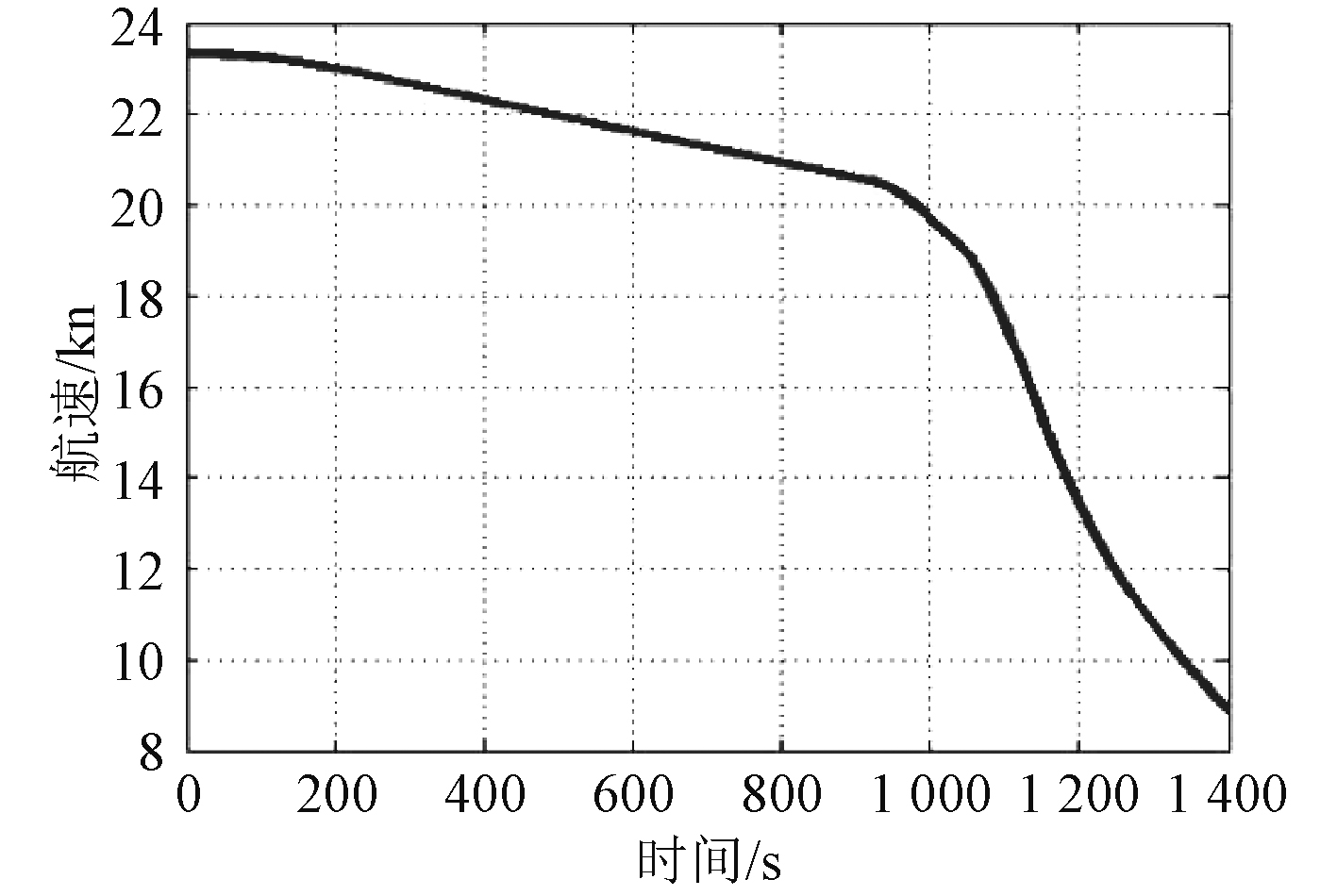
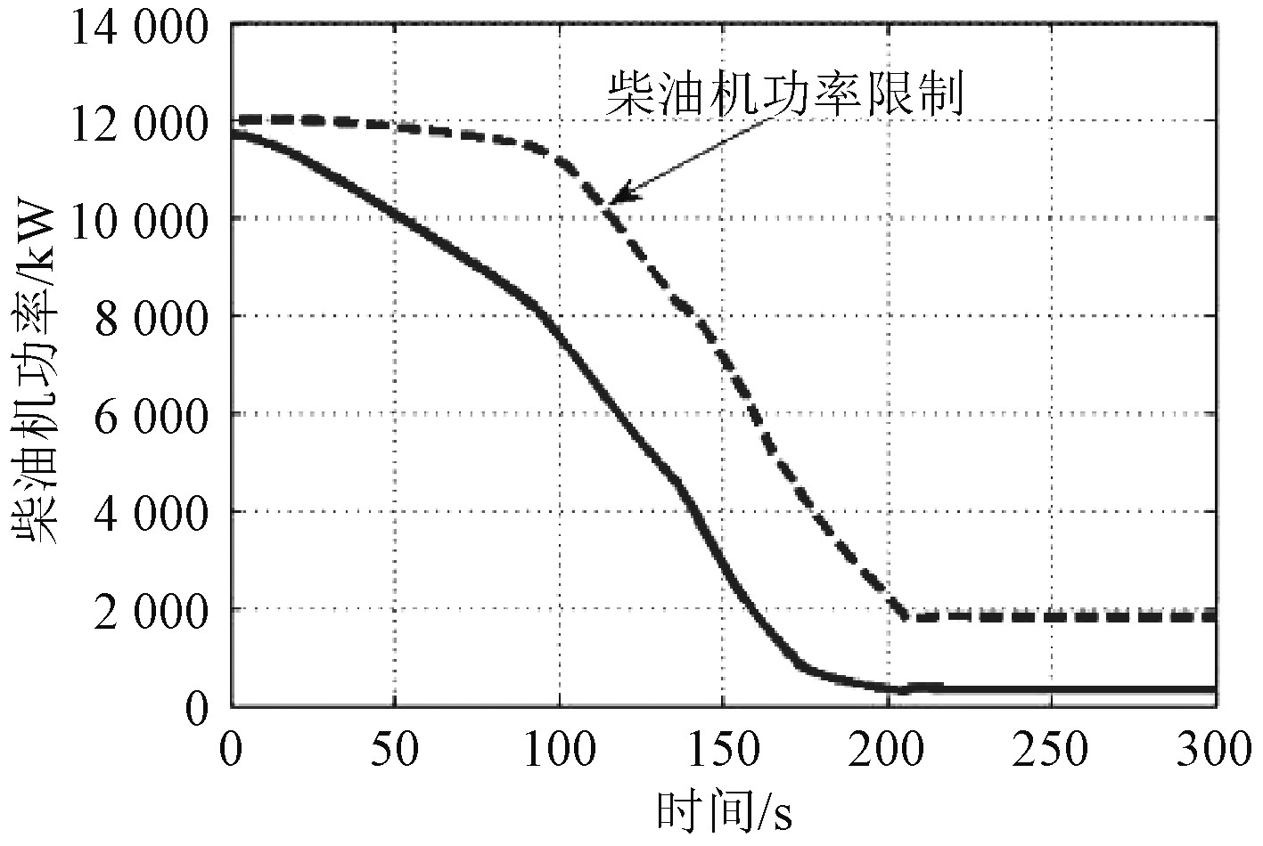
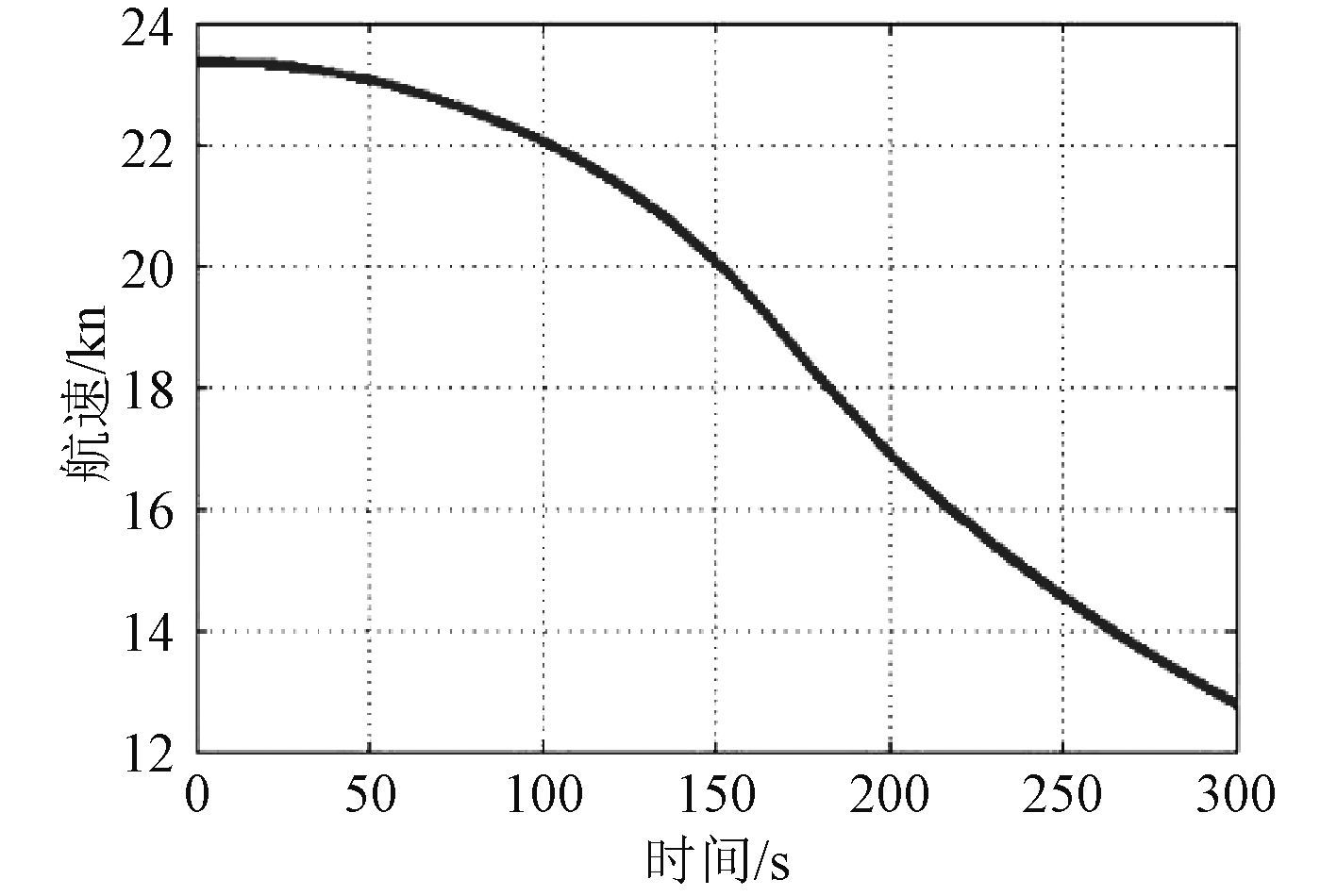
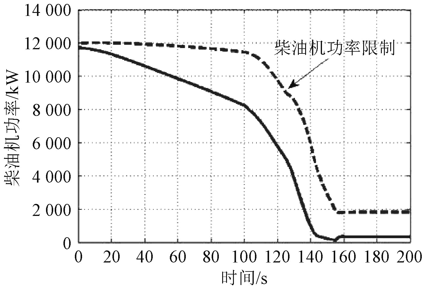
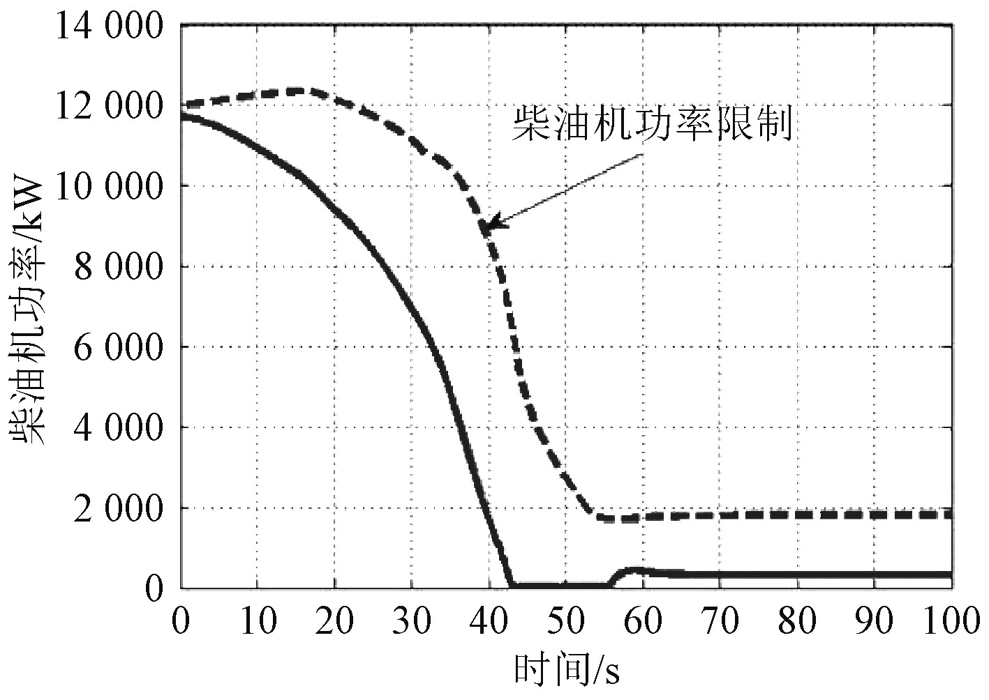
图10~图17为推进系统冷、热机的正常、应急减速过程仿真结果。可以看出,依据目前的减速过程调节时间,主机在冷、热机2种状态下均能保证不超过柴油机功率限制曲线,减速过程缓慢,且航速变化平稳,运行状况较为理想。说明减速过程动态特性良好,可以保证船舶具有较好的航行性能[9]。
|
图 10 冷机正常减速过程主机功率变化规律 Fig. 10 Power variation of main engine during normal deceleration of cooling engine |
|
图 11 冷机正常减速过程航速变化规律 Fig. 11 Ship speed variation during normal deceleration of cooling engine |
|
图 12 冷机应急减速过程主机功率变化规律 Fig. 12 Power variation of main engine during emergency deceleration of cooling engine |
|
图 13 冷机应急减速过程航速变化规律 Fig. 13 Ship speed variation during emergency deceleration of cooling engine |
|
图 14 热机正常减速过程主机功率变化规律 Fig. 14 Power variation of main engine during normal deceleration of heat engine |

|
图 15 热机正常减速过程航速变化规律 Fig. 15 Ship speed variation during normal deceleration of heat engine |
|
图 16 热机应急减速过程主机功率变化规律 Fig. 16 Power variation of main engine during emergency deceleration of heat engine |

|
图 17 热机应急减速过程航速变化规律 Fig. 17 Ship speed variation during emergency deceleration of heat engine |
|
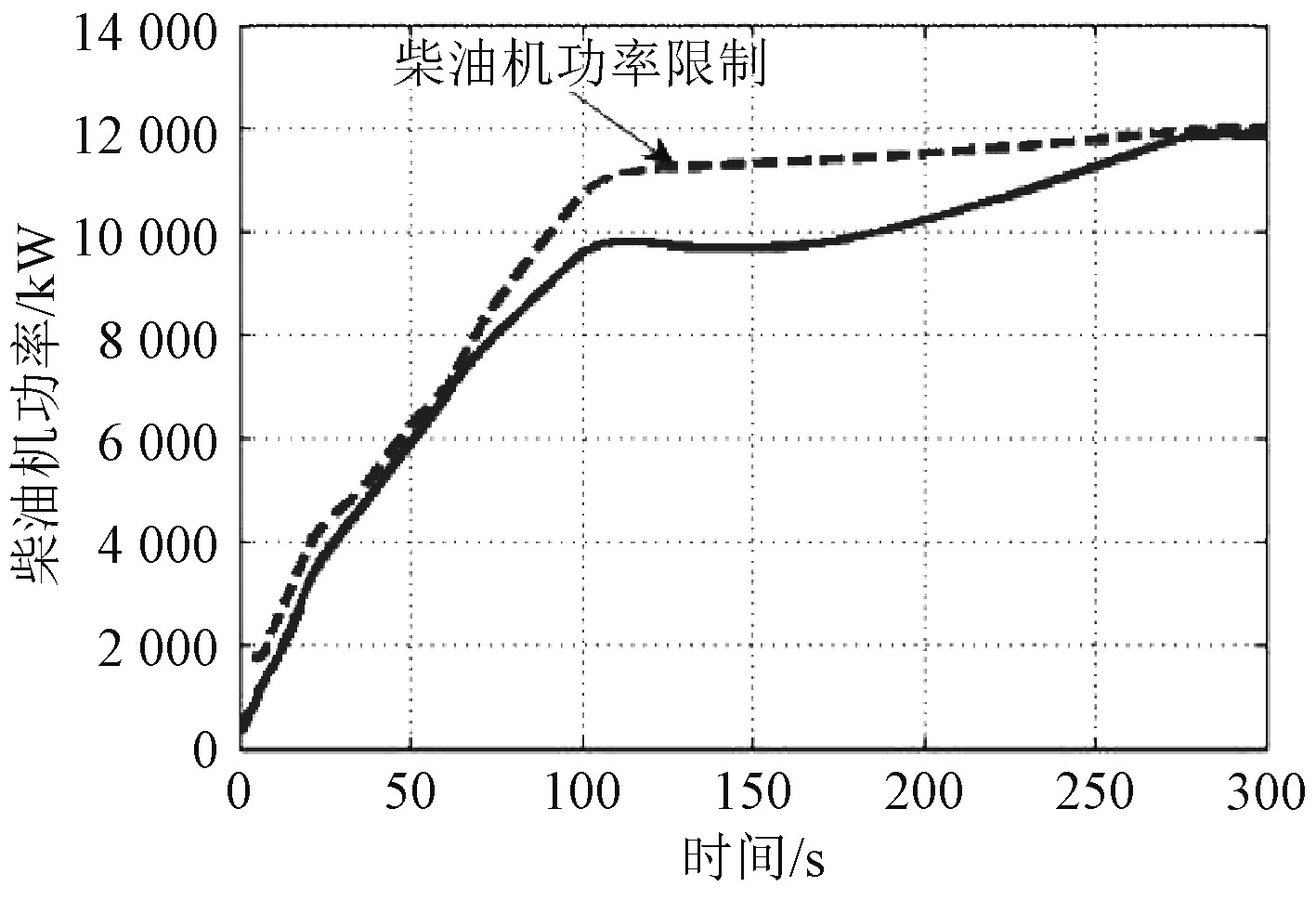
图 18 热机应急加速过程优化后主机功率变化规律 Fig. 18 Power variation of main engine after optimization of heat engine emergency acceleration |
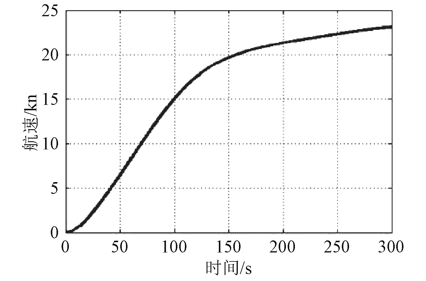
针对热机应急加速工况下主机超负荷严重的情况,对加速过程调节时间进行了反复仿真测试,得到理想的加速时间为550 s,仿真结果如图18和图19所示。可以看出,优化之后的加速过程未出现主机超过柴油机功率限制曲线的情况,运行状况良好,航速增加平稳,动态性能可以满足船舶航行要求。
|
图 19 热机应急加速过程优化后航速变化规律 Fig. 19 Ship speed variation after optimization of heat engine emergency acceleration |
1)综合利用机理建模、经验公式拟合等手段,针对四机双桨推进系统的特点建立了“船-机-桨”数学模型,并基于Simulink仿真环境构建了系统仿真模型,主要包括车令、调速器、柴油机、齿轮箱、调距桨等模块。
2)依据理论设计的动态控制参数对推进系统冷热机的加、减速以及由全正车到全倒车等动态过程进行了仿真研究,得到了主机功率变化规律和全船航速变化规律,分析了各个工况下推进系统的动态加、减速特性,并对超负荷情况较严重的热机应急加速工况进行了仿真优化。
3)推进系统在热机减速、冷机加速、冷机减速工况下航速变化平稳,主机运行状况理想,船舶航行性能较好。在热机加速工况下由于在加速度达到最大时存在转速振荡调整过程,易导致主机出现超负荷现象。通过合理地匹配加速过程调节时间可以避免超负荷问题,优化推进系统的动态性能。
| [1] |
陈虞涛, 曾凡明, 陈国钧, 等. 船舶并车推进装置负荷均衡控制策略研究[J]. 舰船科学技术, 2008, 30(5): 24-28. CHEN Yu-tao, ZENG Fan-ming, CHEN Guo-jun, et al. Study on power control strategy of marine CODAD propulsion plant[J]. Ship Science and Technology, 2008, 30(5): 24-28. DOI:10.3404/j.issn.1672-7649.2008.05.003 |
| [2] |
敖晨阳, 陈华清, 曾凡明, 等. 舰船全柴并车后传动装置定量分析研究[J]. 舰船科学技术, 2002, 24(6): 26-29. AO Chen-yang, CHEN Hua-qing, ZENG Fan-ming, et al. The Study of quantitative analysis for all diesel parallel running transmissions[J]. Ship Science and technology, 2002, 24(6): 26-29. |
| [3] |
宋恩哲, 李晓通, 陆平, 等. 柴柴联合动力装置工况切换及控制策略研究[J]. 哈尔滨工程大学学报, 2003, 24(5): 518-521. SONG En-zhe, LI Xiao-tong, LU Ping, et al. Operating mode’s switch and control strategy of CODAD system[J]. Journal of Harbin Engineering University, 2003, 24(5): 518-521. DOI:10.3969/j.issn.1006-7043.2003.05.011 |
| [4] |
EMIN Korkut, MEHMET Atlar. An Experimental investigation of the effect of foul release coating application on performance, noise and cavitation characteristics of marine propellers[J]. Ocean Engineering, 2012(41): 1-12. |
| [5] |
景民, 陆金铭. Matlab/Simulink仿真技术在舰船推进装置中的应用[J]. 船海工程, 2007, 36(4): 125-127. JING Min, LU Jing-min. Application of Matlab/Simulink in design of the propulsion device of warship[J]. Ship&Ocean engineering, 2007, 36(4): 125-127. DOI:10.3963/j.issn.1671-7953.2007.04.040 |
| [6] |
胡明华, 马来好, 杨杰, 等. 基于AMEsim-Simulink的船舶液压推进系统仿真研究[J]. 船舶工程, 2015, 37(12): 28-30. HU Ming-hua, MA Lai-hao, YANG Jie, et al. Simulation of marine hydraulic propulsion system based on AMESIM-SIMULINK co-simulation[J]. Ship Engineering, 2015, 37(12): 28-30. |
| [7] |
严新平, 李志雄, 刘正林, 等. 大型船舶推进系统与船体耦合动力学研究综述[J]. 船舶力学, 2013, 17(4): 439-449. YAN Xin-ping, LI Zhi-xiong, LIU Zheng-lin, et al. Study on coupling dynamical theory for interaction of propulsion system and hull of large ships: a review[J]. Journal of Ship Mechanics, 2013, 17(4): 439-449. |
| [8] |
孔庆福, 吴家明, 曾凡明. 船舶喷水推进系统数学建模及仿真研究[J]. 船舶工程, 2006, 28(2): 12-16. KONG Qing-fu, WU Jia-ming, ZENG Fan-ming. Mathematical modeling and simulation of marine water-jet propulsion system[J]. Ship Engineering, 2006, 28(2): 12-16. DOI:10.3969/j.issn.1000-6982.2006.02.007 |
| [9] |
王海刚. 高速船可调桨推进系统建模及仿真研究[D]. 武汉: 武汉理工大学, 2008.
|
 2020, Vol. 42
