钢/聚氨酯夹层板(Steel Polyurethane Steel Sandwich Plate)简称SPS夹层板,是由钢质面板和聚氨酯弹性体夹芯材料组成,由于其轻质、高比强度等性能而成为现代科学的研究重点。目前,钢/聚氨酯钢夹层板已经应用于船舶修复上。2009年7月韩国大宇造船海洋工程公司与英国IE公司共同投资成立了“SPS海工技术公司”,双方共同对SPS技术展开研究,并将该技术应用于船用钢板的加工。当SPS夹层板应用于舱口盖时,由于受风浪流的影响,使得航行中的船体发生中拱或中垂现象,此时,夹层板受面内载荷作用的影响,可能会发生屈曲失效导致结构发生破坏。因此对夹层板的屈曲性能分析日益重要且迫在眉睫。
对层合板和夹层板的屈曲分析可追溯到19世纪70年代,Srinivas和Rao[1],Noor[2]建立了层合板和夹层板屈曲分析的弹性解。Reddy和Phan[3]提出采用高阶剪切变形理论来研究层合板的振动和稳定性问题。Reddy和Putcha[4]基于改进的高阶理论,利用混合单元对层合板的稳定性和固有振动进行研究。Fares和Zenkour[5]基于多种板理论研究了非均质复合材料交叉层合板的屈曲和自由振动问题。Kant和Swaminathan[6]提出一种改进的高阶理论求出复合材料层合板和夹层板稳定性分析的解析解。Dafedar[7]使用分层理论研究了夹层板的稳定性,并获得夹层板总体屈曲载荷和皱屈载荷,该理论考虑了夹层板中每一层的位移和应力,涉及到大量变量。Kheirikhah[8]使用改进的高阶理论研究了软夹芯复合材料夹层板的双轴屈曲问题。Grover[9]等基于非多项式剪切变形理论研究了复合材料层合板和夹层板的静态,振动和屈曲响应问题。Fazzolari和Carrera[10]使用卡雷拉统一公式(CUF)并结合里茨法(Ritz)和伽辽金法(Galerkin)研究了基于改进的变分运动板理论的各向异性复合材料层合板和夹层板的热机械屈曲问题,给出了不同热载荷和机械载荷下的屈曲相互作用曲线和稳定性包络线。Khandelwal[11]采用9节点二次单元来研究复合材料层合板和夹层板的自由振动和屈曲响应问题。Ranjbaran等[12]基于LW理论研究了夹层板的稳定性问题,并采用瑞利-里兹法近似确定位移场。Birman和Kardomateas[13]对夹层板的理论分析方法进行了综述。
由于理论方法受限于研究对象的几何形状,载荷和边界条件,Di Sciuva[14]在1986年提出Zig-zag理论(ZZT)。该理论不仅能较真实地描述面内位移发生在厚度上的变化,而且也能较为准确地预测层合板和夹层板的面内位移和应力。作者采用该方法研究了复合材料层合板的静态、振动和屈曲响应问题。白瑞祥等[15]利用Zig-zag理论对复合材料夹层板的自由振动问题进行了研究。Pandit等[16]基于改进的高阶Zig-zag理论研究了夹层板的屈曲,考虑了芯材压缩变形的影响。Sahoo[17]建立了反三角Zig-zag理论,该理论不仅满足层间界面的连续性,又满足板上下表面自由牵引的边界条件。作者通过数值算例,预测了不同模量比、纵横比、跨厚比、载荷和边界条件下复合材料层合板和夹层板的屈曲响应。
基于以上讨论可得出:单层板理论由于没有考虑夹层板的层间影响而过渡预测屈曲临界载荷;Layerwise理论由于需要较多的应变场导致计算量庞大,效率低下。
钢聚氨酯夹层板的面板较薄,芯材较厚,因此横向剪切变形不可忽略。文献[18]对复合材料夹层的面板与芯材均采用了高阶变形理论且取得了较为准确的结果,但因未知量过多,使得计算量太大。本文考虑钢聚氨酯夹层板的结构特征,基于文献[18],提出一种简化的高阶Zig-zag理论,即面板采用1阶剪切变形理论,芯材采用Reddy[19]的高阶变形理论,来研究夹层板的稳定性。重点研究SPS夹层板作为舱口盖受轴向压缩载荷下的屈曲问题,分析几何参数对结构稳定性的影响,为SPS夹层板在船体结构中的设计与推广提供参考。
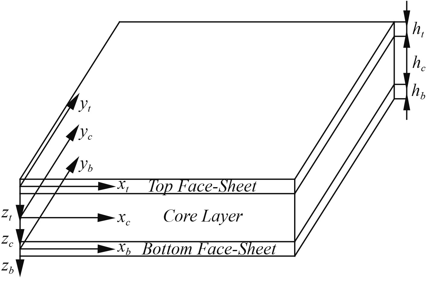
1 简化的高阶Zig-zag理论求解模型在模型中,ht为上面板厚度,hb为下面板厚度,hc为芯层厚度。夹层板的典型坐标系及模型图如图1所示。

|
图 1 夹层板的典型坐标及模型图 Fig. 1 Typical coordinate and model |
夹层板面板的位移场函数为:
| $\begin{array}{l} {u_i} = {u_{0i}} + {z_i}{\theta _{xi}}\text{,}\\ {v_i} = {v_{0i}} + {z_i}{\theta _{yi}}\text{,}\\ {w_i} = {w_{0i}}\text{。} \end{array}$ | (1) |
式中:
夹层板芯材位移场函数为:
| $\begin{array}{l} {u_c} = {u_{0c}} + {z_c}{\theta _{xc}} + z_c^2{\phi _{xc}} + z_c^3{\varphi _{xc}}\text{,}\\ {v_c} = {v_{0c}} + {z_c}{\theta _{yc}}\; + z_c^2{\phi _{yc}} + z_c^3{\varphi _{yc}}\text{,}\\ {w_c} = {w_{0c}}\text{。} \end{array}$ | (2) |
式中:
面板同芯材变形协调,即3个方向上的位移
夹层板上面板与芯材交界处的位移关系:
| $\begin{gathered} {u_t}\left( {{z_t} = \frac{{{h_t}}}{2}} \right) = {u_c}\left( {{z_c} = - \frac{{{h_c}}}{2}} \right) \text{,}\\ {v_t}\left( {{z_t} = \frac{{{h_t}}}{2}} \right) = {v_c}\left( {{z_c} = - \frac{{{h_c}}}{2}} \right)\; \text{,} \\ {w_t}\left( {{z_t} = \frac{{{h_t}}}{2}} \right) = {w_c}\left( {{z_c} = - \frac{{{h_c}}}{2}} \right) \text{,}\\ \end{gathered} $ | (3) |
夹层板下面板与芯材交界处的位移关系:
| $\begin{gathered} {u_b}\left( {{z_b} = - \frac{{{h_b}}}{2}} \right) = {u_c}\left( {{z_c} = \frac{{{h_c}}}{2}} \right) \text{,} \\ {v_b}\left( {{z_b} = - \frac{{{h_b}}}{2}} \right) = {v_c}\left( {{z_c} = \frac{{{h_c}}}{2}} \right) \text{,} \\ {w_b}\left( {{z_b} = - \frac{{{h_b}}}{2}} \right) = {w_c}\left( {{z_c} = \frac{{{h_c}}}{2}} \right) \text{。}\\ \end{gathered} $ | (4) |
上面板与芯材交界处的剪应力关系:
| $\begin{array}{l} \tau _{yz}^t = \tau _{yz}^c,\\ \bar Q_{44}^t\gamma _{yz}^t\left({z_t} = \dfrac{{{h_t}}}{2}\right) + \bar Q_{45}^t\gamma _{xz}^t\left({z_t} = \dfrac{{{h_t}}}{2}\right) = {C_{44}}\gamma _{yz}^c\left({z_c} = - \dfrac{{{h_c}}}{2}\right)\text{,}\\ \tau _{xz}^t = \tau _{xz}^c,\\ \bar Q_{45}^t\gamma _{yz}^t\left({z_t} = \dfrac{{{h_t}}}{2}\right) + \bar Q_{55}^t\gamma _{xz}^t\left({z_t} = \dfrac{{{h_t}}}{2}\right) = {C_{55}}\gamma _{xz}^c\left({z_c} = - \dfrac{{{h_c}}}{2}\right)\text{,} \end{array}$ | (5) |
下面板与芯材交界处的剪应力关系:
| $\begin{array}{l} \tau _{yz}^b = \tau _{yz}^c,\\ \bar Q_{44}^b\gamma _{yz}^b\left({z_b} = - \dfrac{{{h_b}}}{2}\right) + \bar Q_{45}^b\gamma _{xz}^b\left({z_b} = - \dfrac{{{h_b}}}{2}\right) = {C_{44}}\gamma _{yz}^c\left({z_c} = \dfrac{{{h_c}}}{2}\right)\text{,}\\ \tau _{xz}^b = \tau _{xz}^c,\\ \bar Q_{45}^b\gamma _{yz}^b\left({z_b} = - \dfrac{{{h_b}}}{2}\right) + \bar Q_{55}^b\gamma _{xz}^b\left({z_b} = - \dfrac{{{h_b}}}{2}\right) = {C_{55}}\gamma _{xz}^c\left({z_c} = \dfrac{{{h_c}}}{2}\right)\text{。} \end{array}$ | (6) |
根据哈密尔顿原理(Hamilton Principle)推导出夹层板面板和芯材的控制方程。
Hamilton原理的表达式如下:
| $\int_{{t_1}}^{{t_2}} {(\delta U + \delta V - \delta K} ){\rm d}t = 0\text{。}$ | (7) |
式中:
积分并整理得控制方程:
| $\begin{aligned} &\delta {u_0}:\frac{{\partial N_x^t}}{{\partial x}} + \frac{{\partial N_{xy}^t}}{{\partial y}} + \frac{{\partial N_x^c}}{{\partial x}} + \frac{{\partial N_{xy}^c}}{{\partial y}} + \frac{{\partial N_x^b}}{{\partial x}} + \frac{{\partial N_{xy}^b}}{{\partial y}} = 0\text{,}\\ &\delta {v_0}:\frac{{\partial N_y^t}}{{\partial y}} + \frac{{\partial N_{xy}^t}}{{\partial x}} + \frac{{\partial N_y^c}}{{\partial y}} + \frac{{\partial N_{xy}^c}}{{\partial x}} + \frac{{\partial N_y^b}}{{\partial y}} + \frac{{\partial N_{xy}^b}}{{\partial x}} = 0\text{,}\\ &\delta {\theta _{xc}}: - {a_1}\left(\frac{{\partial N_x^t}}{{\partial x}} + \frac{{\partial N_{xy}^t}}{{\partial y}}\right) + \bar Q_{xz}^t\frac{{{C_{55}}}}{{\bar Q_{55}^t}} + {c_1}\left(\frac{{\partial N_x^b}}{{\partial x}} + \right.\\ &\;\;\;\;\;\;\;\;\;\;\left.\frac{{\partial N_{xy}^b}}{{\partial y}}\right) + \bar Q_{xz}^b\frac{{{C_{55}}}}{{\bar Q_{55}^b}} - \frac{{\partial M_x^c}}{{\partial x}} - \frac{{\partial M_{xy}^c}}{{\partial y}} + Q_{xz}^c = 0\text{,}\\ &\delta {\theta _{yc}}: - {a_1}\left(\frac{{\partial N_y^t}}{{\partial y}} + \frac{{\partial N_{xy}^t}}{{\partial x}}\right) + \bar Q_{yz}^t\frac{{{C_{44}}}}{{\bar Q_{44}^t}} + {c_1}\left(\frac{{\partial N_y^b}}{{\partial y}} + \frac{{\partial N_{xy}^b}}{{\partial x}}\right) +\\ &\;\;\;\;\;\;\;\;\;\; \bar Q_{yz}^b\frac{{{C_{44}}}}{{\bar Q_{44}^b}} - \frac{{\partial M_y^c}}{{\partial y}} - \frac{{\partial M_{xy}^c}}{{\partial x}} + Q_{yz}^c = 0\text{,}\\ &\delta {\phi _{xc}}: - {a_2}\left(\frac{{\partial N_x^t}}{{\partial x}} + \frac{{\partial N_{xy}^t}}{{\partial y}}\right) - Q_{xz}^t\frac{{{h_c}{C_{55}}}}{{\bar Q_{55}^t}} - {c_2}\left(\frac{{\partial N_x^b}}{{\partial x}} + \frac{{\partial N_{xy}^b}}{{\partial y}}\right) + \\ &\;\;\;\;\;\;\;\;\;\;Q_{xz}^b\frac{{{h_c}{C_{55}}}}{{\bar Q_{55}^b}} - \frac{{\partial P_x^c}}{{\partial x}} - \frac{{\partial P_{xy}^c}}{{\partial y}} + 2S_{xz}^c = 0\text{,}\\ &\delta {\phi _{yc}}: - {b_2}\left(\frac{{\partial N_y^t}}{{\partial y}} + \frac{{\partial N_{xy}^t}}{{\partial x}}\right) - Q_{yz}^t\frac{{{h_c}{C_{44}}}}{{\bar Q_{44}^t}} - {d_2}\left(\frac{{\partial N_y^b}}{{\partial y}} + \frac{{\partial N_{xy}^b}}{{\partial x}}\right) + \\ &\;\;\;\;\;\;\;\;\;\;Q_{yz}^b\frac{{{h_c}{C_{44}}}}{{\bar Q_{44}^b}} - \frac{{\partial P_y^c}}{{\partial y}} - \frac{{\partial P_{xy}^c}}{{\partial x}} + 2S_{yz}^c = 0\text{,}\\ &\delta {\varphi _{xc}}: - {a_3}\left(\frac{{\partial N_x^t}}{{\partial x}} + \frac{{\partial N_{xy}^t}}{{\partial y}}\right) + Q_{xz}^t\frac{{3h_c^2{C_{55}}}}{{4\bar Q_{55}^t}} - {c_3}\left(\frac{{\partial N_x^b}}{{\partial x}} + \frac{{\partial N_{xy}^b}}{{\partial y}}\right) + \\ &\;\;\;\;\;\;\;\;\;\;Q_{xz}^b\frac{{3h_c^2{C_{55}}}}{{4\bar Q_{55}^b}} - \frac{{\partial R_x^c}}{{\partial x}} - \frac{{\partial R_{xy}^c}}{{\partial y}} + 3T_{xz}^c = 0\text{,}\\ &\delta {\varphi _{yc}}: - {b_3}\left(\frac{{\partial N_y^t}}{{\partial y}} + \frac{{\partial N_{xy}^t}}{{\partial x}}\right) + Q_{yz}^t\frac{{3h_c^2{C_{44}}}}{{4\bar Q_{44}^t}} - {d_3}\left(\frac{{\partial N_y^b}}{{\partial y}} + \frac{{\partial N_{xy}^b}}{{\partial x}}\right) +\\ &\;\;\;\;\;\;\;\;\;\; Q_{yz}^b\frac{{3h_c^2{C_{44}}}}{{4\bar Q_{44}^b}} - \frac{{\partial R_y^c}}{{\partial y}} - \frac{{\partial R_{xy}^c}}{{\partial x}} + 3T_{yz}^c = 0\text{,}\\ &\delta {w_0}:{a_4}\frac{{{\partial ^2}N_x^t}}{{\partial {x^2}}} + {b_4}\frac{{{\partial ^2}N_y^t}}{{\partial {y^2}}} + ({a_4} + {b_4})\frac{{{\partial ^2}N_{xy}^t}}{{\partial x\partial y}} - \frac{{\partial Q_{xz}^t}}{{\partial x}}\frac{{{C_{55}}}}{{\bar Q_{55}^t}} - \\ &\;\;\;\;\;\;\;\;\;\;\frac{{\partial Q_{yz}^t}}{{\partial y}}\frac{{{C_{44}}}}{{\bar Q_{44}^t}} + {c_4}\frac{{{\partial ^2}N_x^b}}{{\partial {x^2}}} + {d_4}\frac{{{\partial ^2}N_y^b}}{{\partial {y^2}}}+\\ &\;\;\;\;\;\;\;\;\;\; ({c_4} + {d_4})\frac{{{\partial ^2}N_{xy}^b}}{{\partial x\partial y}} - \frac{{\partial Q_{xz}^b}}{{\partial x}}\frac{{{C_{55}}}}{{\bar Q_{55}^b}} - \frac{{\partial Q_{yz}^b}}{{\partial y}}\frac{{{C_{44}}}}{{\bar Q_{44}^b}} - \frac{{\partial Q_{xz}^c}}{{\partial x}} - \\ &\;\;\;\;\;\;\;\;\;\;\frac{{\partial Q_{yz}^c}}{{\partial y}} + {{\hat N}_{xx}}\frac{{{\partial ^2}{w_0}}}{{\partial {x^2}}} + 2{{\hat N}_{xy}}\frac{{{\partial ^2}{w_0}}}{{\partial x\partial y}}+\\ &\;\;\;\;\;\;\;\;\;\; {{\hat N}_{yy}}\frac{{{\partial ^2}{w_0}}}{{\partial {y^2}}} + {q_t} - {q_b} = 0\text{。} \end{aligned}$ | (8) |
式中:
| $\begin{array}{l} {{\hat N}_{xx}} = \hat N_{xx}^t + \hat N_{xx}^c + \hat N_{xx}^b\text{,}\\ {{\hat N}_{xy}} = \hat N_{xy}^t + \hat N_{xy}^c + \hat N_{xy}^b\text{,}\\ {{\hat N}_{yy}} = \hat N_{yy}^t + \hat N_{yy}^c + \hat N_{yy}^b\text{。} \end{array}$ | (9) |
当夹层板受双轴压缩载荷时,令
| $\begin{array}{l} {{\hat N}_{xx}} = - {{\hat N}_0}\text{,}\\ {{\hat N}_{yy}} = - K \cdot {{\hat N}_0}\text{,}\\ {{\hat N}_{xy}} = {q_t} = {q_b} = 0\text{。} \end{array}$ | (10) |
式中:K为载荷系数。若K=0,表示夹层板受单轴压缩,反之则表示夹层板受双轴压缩。
1.4 分析求解本文采用纳维叶(Navier)法求解屈曲问题。在Navier解法中,夹层板的刚度系数应满足下述条件:
| ${A_{16}} = {A_{26}} = {A_{45}} = {B_{16}} = {B_{26}} = {D_{16}} = {D_{26}} = 0\text{,}$ |
四边简支的边界条件表示为:
| $\begin{array}{l} x = 0,x = a\text{,}\;\;\;v = {w_0} = {\theta _{xt}} = {\theta _{xc}} = {\theta _{xb}} = 0\text{,}\\ y = 0,y = b\text{,}\;\;\;u = {w_0} = {\theta _{yt}} = {\theta _{yc}} = {\theta _{yb}} = 0\text{。} \end{array}$ | (11) |
假设矩形SPS夹层板的长为a,宽为b,上下面板的厚度分别为ht和hb,芯材的厚度为hc,基于纳维叶解法和位移变量在满足上述边界条件下,选取如下双重三角级数:
| $\begin{gathered} {u_0}(x,y) = \sum\limits_{n = 1}^\infty {\sum\limits_{m = 1}^\infty {{U_{mn}}} } \cos \alpha x\sin \beta y \text{,}\\ {v_0}(x,y) = \sum\limits_{n = 1}^\infty {\sum\limits_{m = 1}^\infty {{V_{mn}}} } \sin \alpha x\cos \beta y \text{,}\\ {\theta _{xc}}(x,y) = \sum\limits_{n = 1}^\infty {\sum\limits_{m = 1}^\infty {X_{mn}^t} } \cos \alpha x\sin \beta y \text{,}\\ {\theta _{yc}}(x,y) = \sum\limits_{n = 1}^\infty {\sum\limits_{m = 1}^\infty {Y_{mn}^t} } \sin \alpha x\cos \beta y \text{,}\\ {\phi _{xc}}(x,y) = \sum\limits_{n = 1}^\infty {\sum\limits_{m = 1}^\infty {X_{mn}^c} } \cos \alpha x\sin \beta y \text{,}\\ {\phi _{yc}}(x,y) = \sum\limits_{n = 1}^\infty {\sum\limits_{m = 1}^\infty {Y_{mn}^c} } \sin \alpha x\cos \beta y \text{,}\\ {\varphi _{xc}}(x,y) = \sum\limits_{n = 1}^\infty {\sum\limits_{m = 1}^\infty {X_{mn}^b} } \cos \alpha x\sin \beta y \text{,}\\ {\varphi _{yc}}(x,y) = \sum\limits_{n = 1}^\infty {\sum\limits_{m = 1}^\infty {Y_{mn}^b} } \sin \alpha x\cos \beta y \text{,} \\ {w_0}(x,y) = \sum\limits_{n = 1}^\infty {\sum\limits_{m = 1}^\infty {{W_{mn}}} } \sin \alpha x\sin \beta y \text{。} \end{gathered} $ | (12) |
式中:
将式(12)代入控制方程式(7)中,得
| ${\left[ { A} \right]_{9 \times 9}}{\left\{ X \right\}_{9 \times 1}} = 0\text{。}$ | (13) |
式中:A为系数矩阵;{X}定义为:
| $\left\{ X \right\} = {\left\{ {{U_{mn}}\;\;{V_{mn}}\;\;X_{mn}^t\;\;\;Y_{mn}^t\;\;X_{mn}^c\;\;Y_{mn}^c\;\;X_{mn}^b\;\;Y_{mn}^b\;\;{W_{mn}}} \right\}^{\rm T}}\text{。}$ |
令系数矩阵A的行列式为0,求解可以得到一组特征值以及对应的特征向量。最小的特征值即为屈曲临界载荷因子,对应的特征向量即为夹层板的屈曲模态。
2 结果与讨论本节使用推导的简化Zig-zag理论来计算夹层板的总体屈曲载荷。通常情况下,总体屈曲对应的半波数m,n分别为1,如果存在更高的半波数且其对应的屈曲临界载荷小于总体屈曲载荷时,那么夹层板将发生皱屈等局部失稳现象。
2.1 对比验证为了与文献[17]的结果进行对比,验证本文理论计算结果的准确性,选取与论文内容相同的结构尺寸和材料参数。即正方形复合材料夹层板,由正交各向异性的层合板面板和各向同性的芯材组成,夹层板的铺层方式为[0/90/Core/90/0],面板与芯材的厚度比tc/tf为10,且面板各单层的厚度均相同。夹层板面板和芯材材料参数如表1所示。屈曲临界载荷的计算结果按式(14)进行无量纲化:
|
|
表 1 夹层板材料参数 Tab.1 Material parameters of composite sandwich plate |
| $\bar N = \frac{{{a^2}{{\hat N}_0}}}{{{E_2}{h^3}}}\text{。}$ | (14) |
式中:E2为夹层板面板的横向弹性模量;h为夹层板的总厚度。
无量纲总体屈曲载荷分别由整体-局部高阶理论(Global-local high-order theory,简称GLHOT)、混合型Layer-wise理论(Mixed layer-wise theory,简称MLWT)、Zig-zag理论(Zig-zag theory,简称ZZT)、反三角Zig-Zag理论(Inverse trigonometric Zig-zag theory,简称ITZZT)、有限元软件Ansys以及本文简化的高阶Zig-zag理论计算所得列于表2,考虑了不同长厚比(a/h=2,4,10,20,30,40,50,60,70,80,90,100)。
|
|
表 2 不同夹层板理论计算无量纲总体屈曲临界载荷对比 Tab.2 Comparisons of the dimensionless overall buckling load for symmetric square sandwich plate |
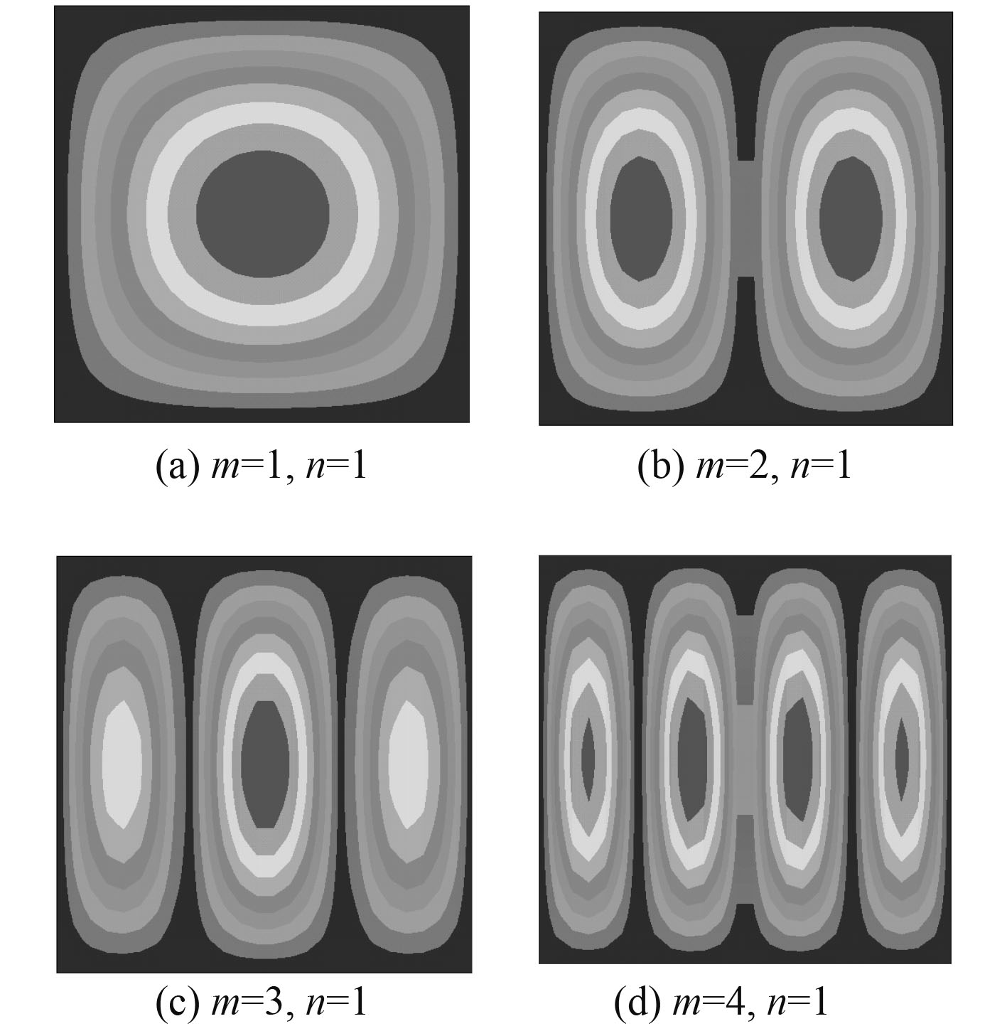
由表1可知,本文计算的结果与混合型Layer-wise理论(MLWT)、Zig-zag理论(ZZT)和反三角Zig-Zag理论(ITZZT)的计算结果相似,最大误差为8.3%。而整体-局部高阶理论(GLHOT)与其他理论的计算结果相比,误差较大,且预测值整体偏高,这是因为其不能很好的处理夹层板相邻间的材料性能导致的。表3和图2分别为夹层板前4阶无量纲屈曲临界载荷及相应的屈曲模态图。
|
|
表 3 前四阶屈曲模态以及对应的无量纲屈曲临界载荷 Tab.3 Buckling mode shapes from the first-order to forth-order and corresponding dimensionless buckling loads |

|
图 2 Ansys计算所得的前四阶屈曲模态 Fig. 2 Contour plots of the buckling shapes obtained by Ansys |
利用本文推导的理论公式结合有限元软件Ansys研究钢聚氨酯夹层板的几何参数对稳定性的影响。面板与芯材的的材料参数取自文献[22],其具体值列于表4。
|
|
表 4 SPS夹层板材料参数 Tab.4 Material parameters of SPS sandwich plate |
本小节讨论不同厚度的面板对SPS夹层板稳定性的影响,以面板厚0.1 mm和芯材厚0.8 mm为基准,分别增重10%,20%,30%和减重10%,20%,30%为条件,得到7种面板厚度,分别为0.147 mm,0.132 mm,0.116 mm,0.1 mm,0.084 mm,0.068 mm,0.053 mm。其中确定参数为:芯材厚度tc=0.8 mm和长宽比a/b=0.5。计算结果列于表5,并且给出了载荷系数K=0和K=1下的屈曲临界载荷。
|
|
表 5 面板厚度不同的夹层板的屈曲临界载荷对比 Tab.5 Comparison of critical buckling load of sandwich plates with differentthicknesses of face-sheet |
图3给出了面板厚度对SPS夹层板的屈曲载荷关系。由图可知,夹层板的抗屈曲性能随面板厚度的减少而迅速降低,在曲线的初始阶段,夹层板的屈曲载荷的下降速率明显大于后半段。由于在夹层结构中,面板提供结构的面内刚度和强度,其主要承受由拉压弯引起的面内拉压应力和剪切应力,所以当面板的厚度减少时,夹层结构的刚度也相应降低,稳性也随之降低。

|
图 3 面板厚度对屈曲临界载荷的关系曲线 Fig. 3 Relation curve of face-sheet thickness to critical buckling load |
本小节讨论不同厚度的芯材对SPS夹层板稳定性的影响,以面板厚0.1 mm和芯材厚0.8 mm为基准,分别增重10%,20%,30%和减重10%,20%,30%为条件,得到7种芯材厚度,分别为1.453 mm,1.235 mm,1.018 mm,0.8 mm,0.582 mm,0.365 mm,0.147 mm。其中确定参数为:面板厚度tf=0.1 mm和长宽比a/b=0.5。计算结果列于表6,并给出了载荷系数K=0和K=1下的屈曲临界载荷。
|
|
表 6 芯材厚度不同的夹层板的屈曲临界载荷对比 Tab.6 Comparison of critical buckling loads of sandwich plate with different core thicknesses |
图4为芯材厚度对SPS夹层板屈曲载荷的关系图。由图可知,夹层板屈曲临界载荷随着芯材厚度的增加而增加。这是因为在夹层结构中,夹层板的弯曲刚度受面板性能和上下面板之间高度的影响,当芯材厚度增大时,意味着增加了上下面板之间的高度,导致结构的弯曲刚度得到加强,自然抗失稳的能力也就增强。

|
图 4 芯材厚度对临界屈曲载荷的影响关系曲线 Fig. 4 Relation curve of core thickness to critical buckling load |
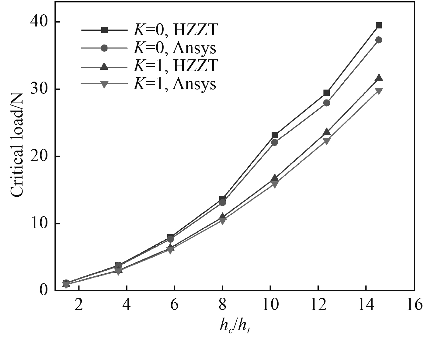
图5描述了在质量增比相同的情况下面板与芯材厚度对SPS夹层板屈曲载荷的影响。由图可知,当结构总质量每增加10%时,芯材厚度对SPS夹层板稳定性的影响更加敏感。因此,在考虑SPS夹层板质量的前提下,若想快速提高SPS夹层结构的稳性,宜优先增加芯材即聚氨酯的厚度。

|
图 5 不同质量增比下,面板和芯材厚度对屈曲载荷的影响关系曲线 Fig. 5 Influence curves of face-sheet and core thickness on critical buckling load at different mass increasing ratios |
本文首先建立简化的高阶Zig-zag数学分析模型,在该模型中面板采用一阶剪切变形理论,芯材采用Reddy高阶剪切变形理论,在满足各项连续条件的前提下,选用纳维叶(Navier)法求解简支板的屈曲临界载荷。然后重点讨论了几何参数对SPS夹层板稳定性的影响,并辅以有限元软件Ansys作为对比,可以得出以下结论:
1)本文理论计算的总体屈曲临界载荷与其他理论计算方法吻合度较高,说明本文方法的合理性和准确性。
2)板厚对SPS夹层板的稳定性影响较大,当考虑结构的质量时,增加芯材(聚氨酯)的厚度更能提升结构的抗屈曲性能。
| [1] |
SRINIVAS S, RAO AK. Bending, vibration and buckling of thick orthotropic rectangular plates and laminates[J]. Int J Solids Struct, 1970, 6(11): 1463-81. DOI:10.1016/0020-7683(70)90076-4 |
| [2] |
NOOR AK. Stability of multilayered composite plates[J]. Fiber Sci Technol, 1975, 8(2): 81-9. DOI:10.1016/0015-0568(75)90005-6 |
| [3] |
REDDY JN, PHAN ND. Stability and vibration of isotropic, orthotropic and laminated plates according to a higher order shear deformation theory[J]. JSound Vib, 1985, 2: 157-70. |
| [4] |
PUTCHA NS, REDDY JN. Stability and natural vibration analysis of laminated plates by using a mixed element based on a refined theory[J]. J Sound Vib, 1986, 104(2): 285-300. DOI:10.1016/0022-460X(86)90269-5 |
| [5] |
FARES ME, ZENKOUR AM. Buckling and free vibration of non-homogenous composite cross-ply laminated plates with various plate theories[J]. Compos Struct, 1999, 44: 279-87. DOI:10.1016/S0263-8223(98)00135-4 |
| [6] |
KANT T, SWAMINATHAN K. Analytical solution using a higher order refined theory for the stability analysis of laminated composites and sandwich plates[J]. Struct Eng Mech, 2000, 10(4): 337-57. DOI:10.12989/sem.2000.10.4.337 |
| [7] |
DAFEDAR JB, DESAI YM, MUFTI AA. Stability of sandwich plates by mixed higher order analytical formulation[J]. Int J Solids Struct, 2003, 40(17): 4501-17. DOI:10.1016/S0020-7683(03)00283-X |
| [8] |
KHEIRIKHAH MM, KHALILI SMR, Malekzadeh Fard K. Biaxial buckling analysis of soft-core composite sandwich plates using improved higher-order theory[J]. Eur J Mech A/solids, 2012, 31: 54-66. DOI:10.1016/j.euromechsol.2011.07.003 |
| [9] |
GROVER N, SINGH BN, MAITI DK. New non-polynomial shear-deformation theories for the structural behavior of laminated-composite and sandwich plates[J]. AIAA J, 2013, 51(8): 1861-71. DOI:10.2514/1.J052399 |
| [10] |
FAZZOLARI FA, CARRERA E. Thermo-mechanical buckling analysis of anisotropic multilayered composite and sandwich plates by using refined variable kinematics theories[J]. J Thermal Stresses, 2013, 36: 321-50. DOI:10.1080/01495739.2013.770642 |
| [11] |
KHANDELWAL RP, CHAKRABARTI A, BHARGAVA P. Vibration and buckling analysis of laminated sandwich plate having soft core[J]. Int J Struct Stab Dyn, 2013, 13(8): 20-31. |
| [12] |
RANJBARAN A, KHOSHRAVAN MR, KHARAZI M. Buckling analysis of sandwich plate using layerwise theory[J]. J Mech Sci Tech, 2014, 28(7): 2769-77. DOI:10.1007/s12206-014-0512-9 |
| [13] |
BIRMAN, V., KARDOMATEAS, G .. Review of current trends in research and applications of sandwich structures[J]. Composites Part B: Engineering, 2018, 142: 221-240. DOI:10.1016/j.compositesb.2018.01.027 |
| [14] |
DI SCIUVA M. Bending, vibration and buckling of simply supported thick multilayered orthotropic plates: an evaluation of new displacement model[J]. J Sound Vib, 1986, 105(3): 425-44. DOI:10.1016/0022-460X(86)90169-0 |
| [15] |
白瑞祥, 张志峰, 陈浩然. 基于Zig-Zag变形假定的复合材料夹层板的自由振动[J]. 力学季刊, 2004, 25(4): 529-534. BAI Rui-xiang, ZHANG Zhi-feng, CHEN Hao-ran. Free vibration of composite laminated plates based on Zig-Zag deformation assumption[J]. Chinese Quarterly of Mechanics, 2004, 25(4): 529-534. |
| [16] |
PANDIT MK, SINGH BN, SHEIKH AH. Buckling of laminated sandwich plates with soft core based on an improved higher order zigzag theory[J]. Thin-Wall Struct, 2008, 46(11): 1183-91. DOI:10.1016/j.tws.2008.03.002 |
| [17] |
SAHOO, R., SINGH, B. N.. Assessment of inverse trigonometric zigzag theory for stability analysis of laminated composite and sandwich plates[J]. International Journal of Mechanical Sciences, 2015, 101-102: 145-154. DOI:10.1016/j.ijmecsci.2015.07.023 |
| [18] |
KHEIRIKHAH M M, KHALILI S M R, FARD K M. Biaxial buckling analysis of soft-core composite sandwich plates using improved high-order theory[J]. European Journal of Mechanics-A/Solids, 2012, 31(1): 54-66. DOI:10.1016/j.euromechsol.2011.07.003 |
| [19] |
REDDY J N. Mechanics of laminated composite plates and shells: theory and analysis[M]. CRC Press, 2004.
|
| [20] |
LO SH, ZHEN W, SZE KY, WANJI C. An improved in-plane displacement model for the stability analysis of laminated composites with general lamination configuration[J]. Compos Struct, 2011, 93: 1584-94. DOI:10.1016/j.compstruct.2011.01.006 |
| [21] |
PANDIT MK, SINGH BN, SHEIKH AH. Buckling of sandwich plates with random material properties using improved plate model[J]. AIAA J, 2009, 47(2): 418-28. DOI:10.2514/1.39180 |
| [22] |
商磊. SPS复合钢板屈曲分析及其优化设计[D]. 哈尔滨: 哈尔滨工程大学, 2013. SHANG lei. Buckling analysis and optimization design of SPS composite steel plate [D]. Harbin engineering university, 2013. |
 2019, Vol. 41

