2. 武汉第二船舶设计研究所,湖北 武汉 430000
2. Wuhan Second Ship Design and Research Institute, Wuhan 430064, China
换热器是船用动力装置的重要组成设备,由于管壳式换热器具有传热效率高、结构紧凑以及密封性能良好等优点,使得其在舰船动力装置中被广泛采用[1 – 2]。同时利用集中冷却方案可实现动力设备冷却功能的集成,大大简化了系统及设备配置,有力提高了舰船二回路系统总体集成优化设计水平。因此舰船集成式换热器具有较好的应用前景。
由于数值模拟方法具有使用方便、灵活,研究和开发周期短,费效比高等优点,使其成为换热器设计中的常用手段之一,1972年Patan-kar首先利用数值模拟技术实现了换热器传热与流动模拟研究[3]。后续研究者通过不断更新计算机硬件水平以及发展新的计算理论和方法,有效推进了数值模拟在计算效率、准确性等性能的全面提升[4 – 5]。
本文借助CFD分析软件,构建合理的仿真模型,采用合理的计算方法和边界条件,完成了某型舰船集成式管壳换热器(结构示意如图1所示)的壳程流场和温度场数值模拟仿真分析。

|
图 1 两端组合集成式管壳换热器结构 Fig. 1 Structural of two-section integrated shell-and-tube heat exchanger |
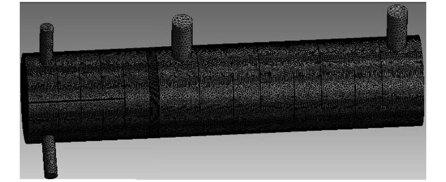
数值模拟分析对网格划分要求很高,网格划分品质越高,数值仿真计算速度和计算结果的收敛性越好。本文在对换热器结构充分研究基础上,构建了壳程流场简化计算模型。集成换热器模型结构比较规则,因此选用六面体结构化网格进行网格划分。为消除网格的疏密程度对模型计算结果的影响,根据网格独立性测算优化结果选择了最合适的精细化网格划分方案构建了完整的计算区域网格(如图2所示)。
|
图 2 计算区域网格 Fig. 2 Computation grid of heat exchanger |
质量守恒、动量守恒和能量守恒方程是数值模拟方法中常规应用流场计算控制方程,本文数值模拟应用的控制守恒方程如下:
连续方程
| $ \frac{{\partial {u_x}}}{{\partial x}} + \frac{{\partial {{{u}}_{{y}}}}}{{\partial {{y}}}} + \frac{{\partial {{{u}}_{{z}}}}}{{\partial {{z}}}} = 0\text{。} $ | (1) |
动量方程
| $ {u_x}\frac{{\partial {u_i}}}{{\partial x}} \!+\! {u_{\rm{y}}}\frac{{\partial {u_i}}}{{\partial {\rm{y}}}} \!+\! {u_z}\!\frac{{\partial {u_i}}}{{\partial z}} \!=\! \!-\! \frac{1}{\rho }\!\frac{{\partial {{p}}}}{{\partial {x_i}}} \!+\! \nu \left(\!\frac{{{\partial ^2}{u_i}}}{{\partial {x^{\rm{2}}}}} \!+\! \!\frac{{{\partial ^2}{u_i}}}{{\partial {{\rm{y}}^{\rm{2}}}}} \!+\! \frac{{{\partial ^2}{u_i}}}{{\partial {z^{\rm{2}}}}}\!\right)\text{。} $ | (2) |
其中:ui分别为ux,uy,uz;xi为所选坐标。
能量方程
| $ {u_x}\frac{{\partial t}}{{\partial x}} + {u_y}\frac{{\partial t}}{{\partial y}} + {u_z}\frac{{\partial t}}{{\partial z}} = \alpha\left(\frac{{{\partial ^2}t}}{{\partial {x^{\rm{2}}}}} + \frac{{{\partial ^2}t}}{{\partial {y^{\rm{2}}}}} + \frac{{{\partial ^2}t}}{{\partial {z^{\rm{2}}}}}\right)\text{。} $ | (3) |
固体部分(导热方程)
| $ \frac{{{\partial ^2}t}}{{\partial {{{x}}^{\rm{2}}}}} + \frac{{{\partial ^2}t}}{{\partial {{{y}}^{\rm{2}}}}} + \frac{{{\partial ^2}t}}{{\partial {{{z}}^{\rm{2}}}}} = 0\text{。} $ | (4) |
液体部分(对流方程)
| $ \begin{array}{l} \left({\rho _{\rm{2}}}{\nu _x}\displaystyle\frac{{\partial {h_{\rm{2}}}}}{{\partial x}} + {\rho _{\rm{2}}}{\nu _y}\frac{{\partial {h_{\rm{2}}}}}{{\partial y}} + {\rho _{\rm{2}}}{\nu _z}\frac{{\partial {h_{\rm{2}}}}}{{\partial z}}\right) - \\ \left[ {\displaystyle\frac{\partial }{{\partial x}}\left({\lambda _2}\frac{{\partial t}}{{\partial x}}\right) + \frac{\partial }{{\partial y}}\left({\lambda _2}\frac{{\partial t}}{{\partial y}}\right) + \frac{\partial }{{\partial z}}\left({\lambda _2}\frac{{\partial t}}{{\partial z}}\right)} \right] = \\ {\nu _x}\displaystyle\frac{{\partial p}}{{\partial x}} + {\nu _y}\frac{{\partial p}}{{\partial y}} + {\nu _z}\frac{{\partial p}}{{\partial z}}\text{。} \end{array} $ | (5) |
流固耦合部分,耦合边界上温度连续
| $ {t_{w1}} = {t_{w2}}\text{。} $ | (6) |
耦合边界上的第三类边界条件
| $ - \lambda {\left( {\frac{{\partial {\rm{t}}}}{{\partial {\rm{n}}}}} \right)_{w1}} = h({t_{w2}} - {t_{f2}})\text{。} $ | (7) |
为了综合平衡计算效率与计算精度,本文在数值仿真计算时应用计算方法如下:
1)计算模型,标准层流模型;
2)压力和速度耦合算法,SIMPLE;
3)连续方程计算收敛条件,变量残差达到10–3;
4)动量方程计算收敛条件,变量残差达到10–3;
5)能量方程计算收敛条件,变量残差达到10–6。
同时,根据集成换热器结构特征,在模型构建中设定边界条件如下:
1)固体部分,铜质换热管;
2)流体部分,稳态不可压缩的水;
3)固壁面,无滑移静止壁面;
4)换热壁面,热流量恒定第二类边界;
5)对称面,对称边界。
3 计算结果及分析为了充分掌握某型舰船集成式管壳换热器相关性能,本文结合集成换热器初步设计相关性能参数,构建数值仿真计算模型,完成了壳程流场及温度场数值仿真计算,给出了对称面和各横截面上的热流场,以全面反映换热器壳程流动以及传热特性。
在图1所示的计算区域中,流动方向沿z轴正方向,以右端面中心为坐标原点,对换热器的左端和右端,在壳程流动中z方向上各折流板中间位置分别画出横截面,并给出各横截面上的温度、压力和速度分布。
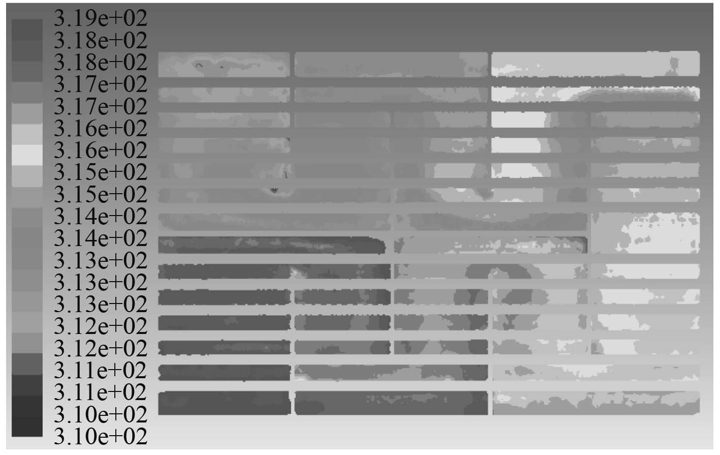
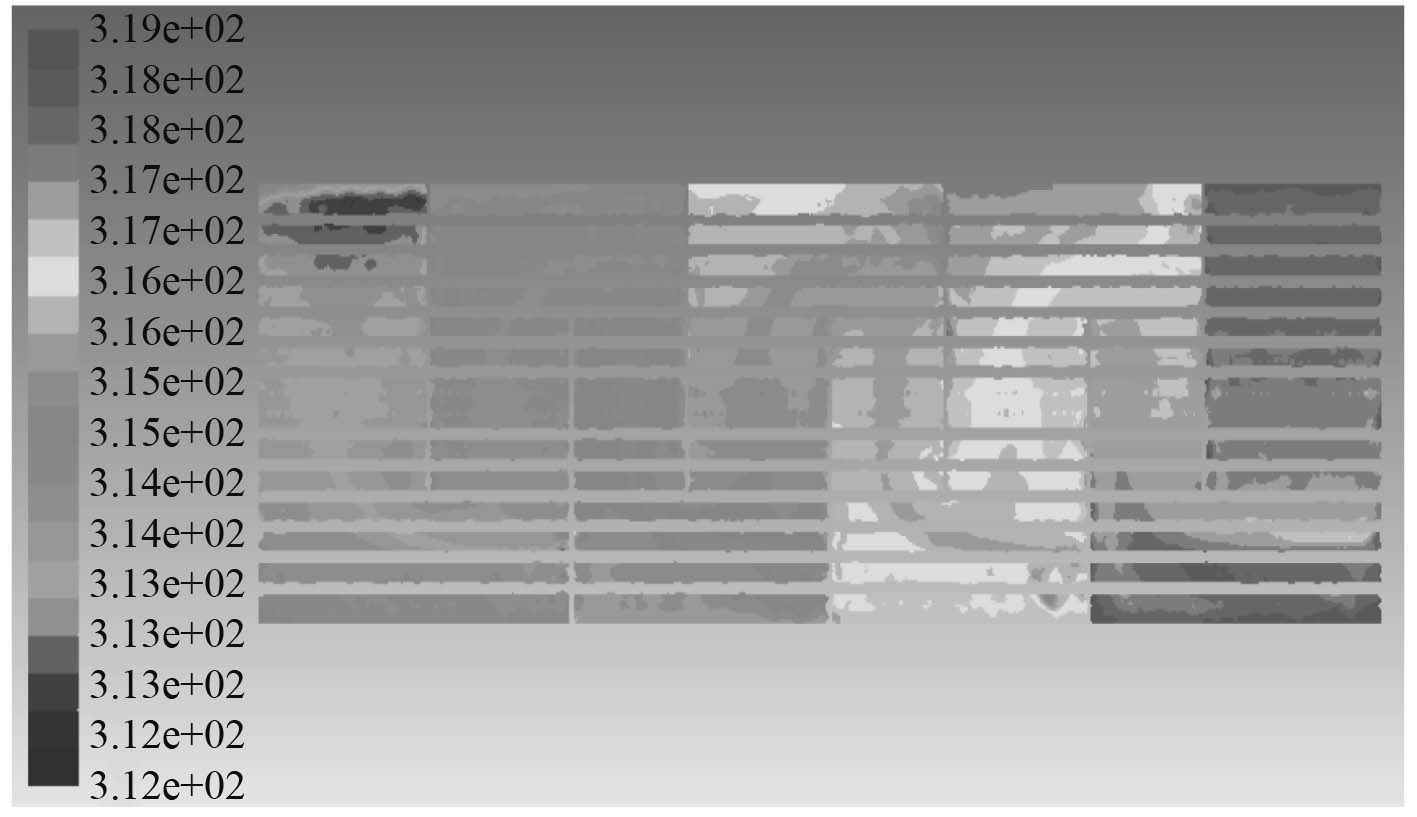
3.1 温度场数值模拟分析集成换热器左端和右端对称面上的温度分布如图3和图4所示。由图3可见,左端被水平中间挡板分为上下两半段,壳程流动为二流程,换热器中壳程介质温度沿流动方向逐步降低,在出口附近温度约35 ℃。由图4可见,在设计工况下,换热器中右端壳程介质温度沿流动方向逐步降低,在出口附近温度约35 ℃。
|
图 3 左端对称面上的温度分布 Fig. 3 Distribution of the temperature of the fluid at the symmetry plane of the left part |
|
图 4 右端对称面上的温度分布 Fig. 4 Distribution of the temperature of the fluid at the symmetry plane of the right part |
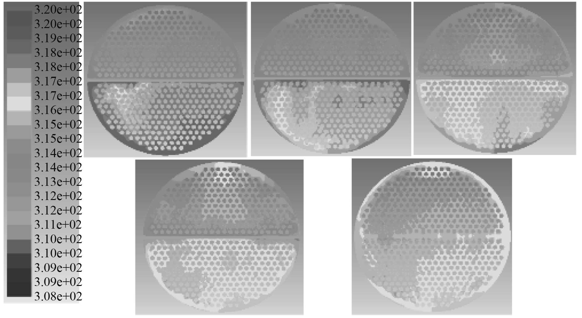
左端Z方向各典型横截面上的温度分布如图5所示。最后一个典型横截面由于处于尾部均匀流动区,因此该截面上温度分布均匀。由于壳程设计为双流程,在其他横截面上存在2个温度均匀区,即具有较高温度、离入口较近的下半段和温度较低、离出口较近的上半段。
|
图 5 左端Z方向横截面上的温度分布 Fig. 5 Distribution of the temperature of the fluid at the Z cross-section of the left part |
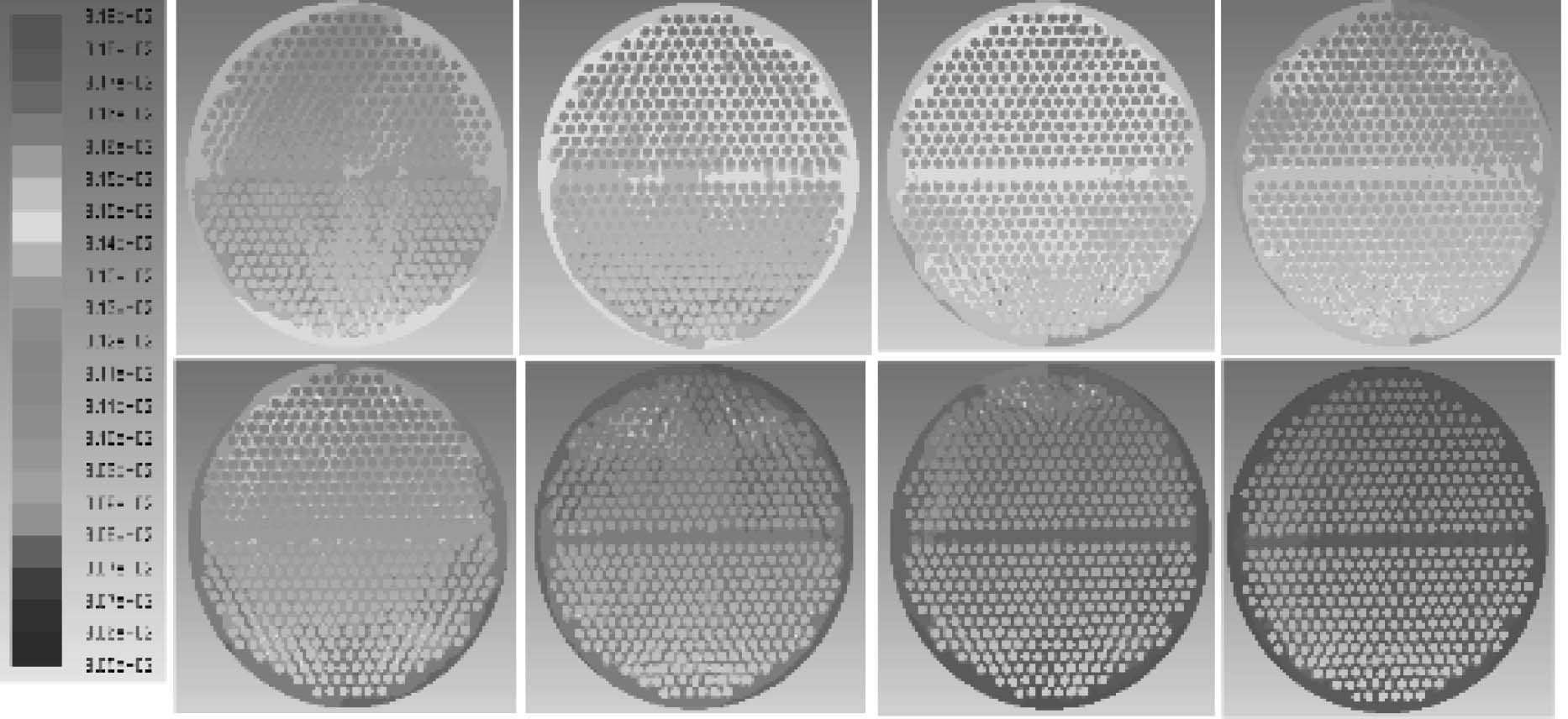
右端Z方向各典型横截面上的温度分布如图6所示,选取的横截面位置是相邻折流板中间位置。由图6可见,温度在各横截面上的分布比较均匀。由于右端壳程流体是从右端流入、右端流出,所以沿着流动方向,即随着Z坐标的减少,温度逐渐降低。
|
图 6 右端Z方向横截面上的温度分布 Fig. 6 Distribution of the temperature of the fluid at the Z cross-section of the right part |
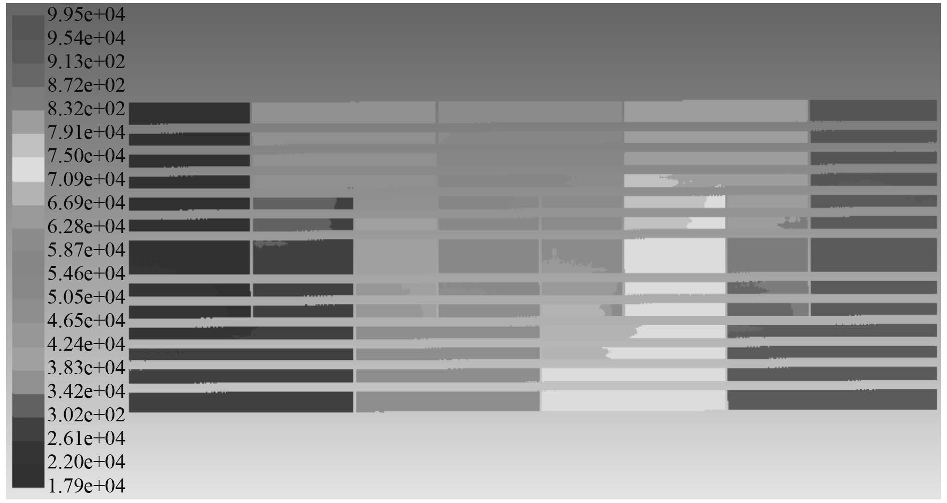
集成换热器左端和右端对称面上的压力分布如图7和图8所示。可知,壳程介质压力沿流动方向逐步降低,压力的降低具有一定的周期性规律,这一规律与折流板排布的几何周期性相一致。

|
图 7 左端对称面上的压力分布 Fig. 7 Distribution of the pressure of the fluid at the symmetry plane of the left part |
|
图 8 右端对称面上的压力分布 Fig. 8 Distribution of the pressure of the fluid at the symmetry plane of the right part |
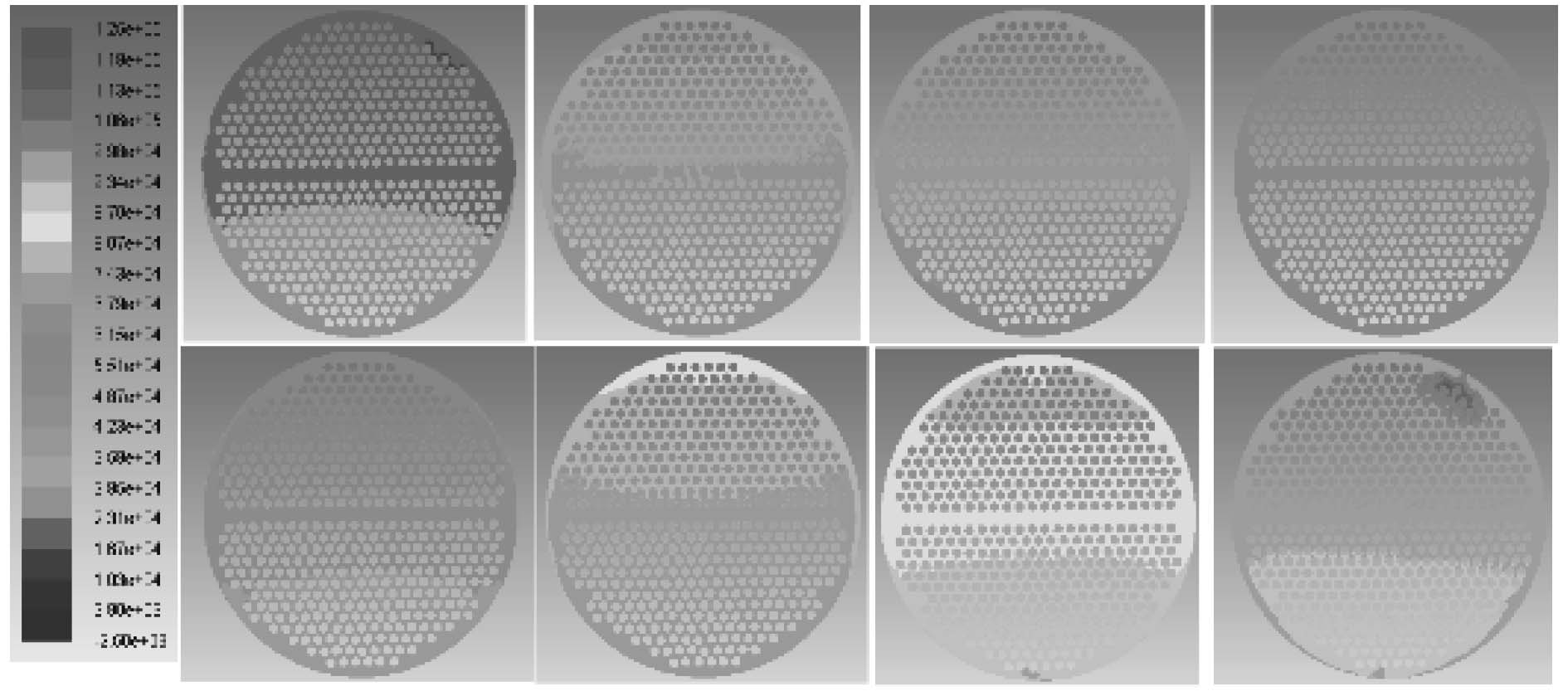
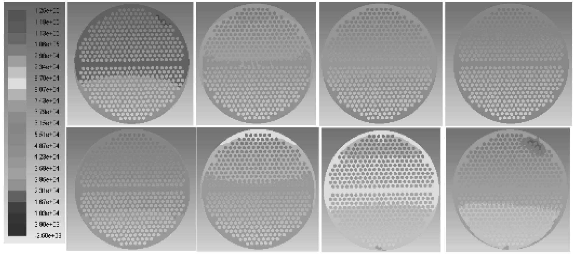
左端Z方向各典型横截面上的压力分布如图9所示。右端Z方向各典型横截面上的压力分布如图10所示。可知,各横截面上压力分布沿流动方向逐渐降低。这一规律与图7和图8反映的现象相互吻合,折流板是换热器流动阻力的主要来源,其对换热器壳程内部流场阻碍作用显著。
|
图 9 左端Z方向横截面上的压力分布 Fig. 9 Distribution of the pressure of the fluid at the Z cross-section of the left part |
|
图 10 右端Z方向横截面上的压力分布 Fig. 10 Distribution of the pressure of the fluid at the Z cross-section of the right part |
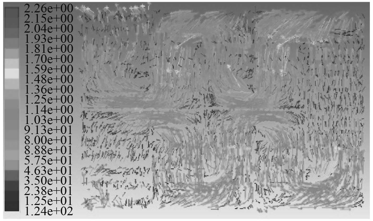
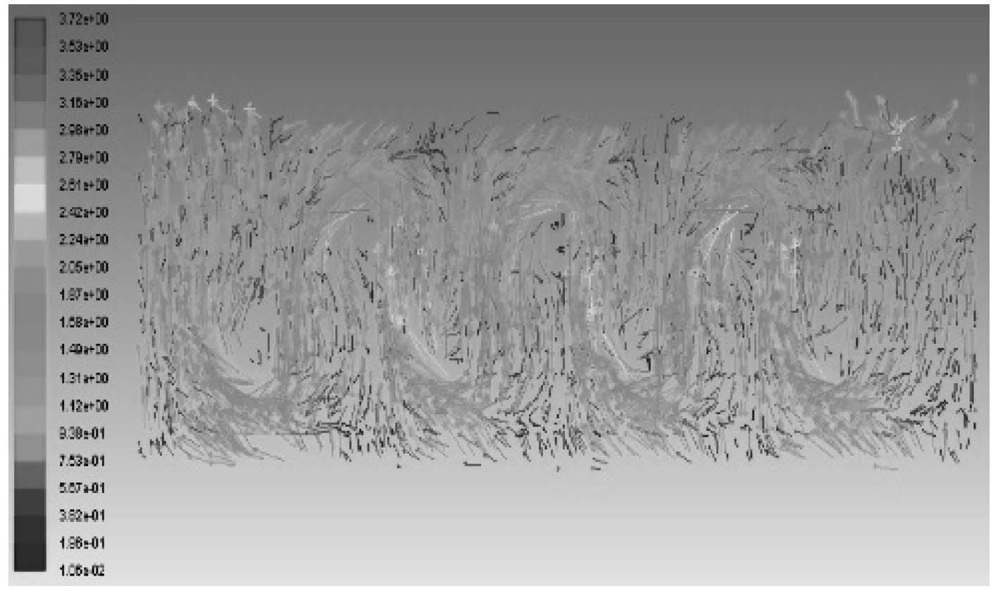
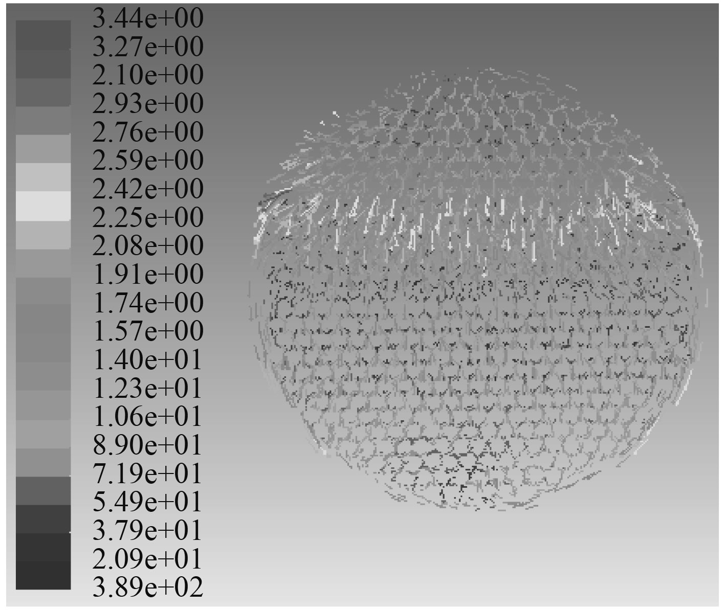
集成换热器左端和右端对称面上的速度矢量图如图11和图12所示。可知,折流板对流体的轴向流动阻碍作用显著,折流板处流体流速存在陡变现象,特别是在折流板圆缺处流体流速显著提升。流动方向各横截面上的速度分布规律基本相同,故图13和图14给出了典型横截面上的速度分布,截面取自中间两块折流板之间,在折流板圆缺处流体流速显著提升。流场分布比较均匀,但在折流板与换热器壳体相切的区域形成了显著的周向对称环流,在换热管四周存在小范围的局部环流,但滞流效应不显著,不存在显著的滞流区。
|
图 11 左端对称面上的速度矢量图 Fig. 11 Velocity vector of the fluid at the symmetry plane of the left part |
|
图 12 右端对称面上的速度矢量图 Fig. 12 Velocity vector of the fluid at the symmetry plane of the right part |

|
图 13 左端Z方向典型横截面速度矢量图 Fig. 13 Velocity vector of the fluid at the typical Z cross-section of the left part |
|
图 14 右端Z方向典型横截面速度矢量图 Fig. 14 Velocity vector of the fluid at the typical Z cross-section of the right part |
本文借助CFD软件,在对某型集成式换热器合理简化基础上,构建了相应的数值分析耦合传热模型,全面模拟了换热器壳程流场和温度场,仿真分析的主要结论如下:
1)换热器设计比较合理,流动区域中换热比较均匀,折流板的使用对于换热有强化作用。
2)壳程流体温度与压力沿流动方向逐渐降低,这一规律与折流板排布相一致。
3)流动阻力的主要来源来自于折流板,流体的轴向流动受到折流板的阻挡作用显著。
4)在流通截面突变对流动的搅浑作用显著,形成高速流动区和回流滞流区,速度分布也具有周期性规律。速度分布也具有周期性规律。
本文研究全面反映了换热器内部流体流动与传热细节信息,可有效发现设计薄弱环节,为换热器性能的进一步提升奠定了良好的技术基础。
| [1] |
邱金荣, 等. 船用换热设备选型分析及小型化技术应用研究[J]. 舰船科学技术, 2012, 34(10): 98-101. DOI:10.3404/j.issn.1672-7649.2012.10.021 |
| [2] |
钱颂文. 换热器设计手册[M]. 北京. 化学工业出版社. 2002.
|
| [3] |
PATANKAR, S. V., SPALDING, D. B. Heat Exchanger Design Theory Sourcebook [M]. London: McGRAWHILL Book Company, 1974.
|
| [4] |
董其伍, 王丹, 等. 板翅式换热器数值模拟研究[J]. 化工设备与管道[J], 2008, 45(2): 25-27. |
| [5] |
赵晓曦, 邓先和, 陈颖, 等. 管壳式换热器壳程传热强化研究[J]. 现代化工, 2001, 21(7): 14-17. DOI:10.3321/j.issn:0253-4320.2001.07.004 |
 2019, Vol. 41
