小管径微肋管以其经济高效和节能的显著特点,已得到广泛应用。自1977年日立公司[1]正式提出微肋管想法后,国内外很多学者[2 – 5]对其进行改进研究。图1为微肋管的结构图。目前国内外的空调公司均推出了自己的微肋管产品,在家用和车用空调中得到广泛应用。

|
图 1 微肋管的结构示意图 Fig. 1 Diagram of micro-fin tube |
作为舰船保障系统的一部分,空调系统能够为各级用户提供适宜的温湿度,其安全稳定的运行具有重要意义。随着舰船向小型化、紧凑化发展,船用空调系统换热器也面临很多挑战,通过强化换热来减少体积是其中一个发展方向。
关于换热管强化换热实验研究的较多[2 – 10],但在蒸发管沸腾换热数值模拟方面研究较少。作为R22的在家用空调中的替代工质,R410A在舰船空调中研究较少。基于此,本文通过数值模拟研究了R22和R410A在外径为5 mm的微肋管管内沸腾过程中的换热特性,与已有的实验结果进行对照,以期通过数值模拟手段进行新型换热管开发及制冷工质替换研究。
1 物理模型模拟的微肋管管外径为5 mm,螺旋角为0°(以下简称直肋管),其他几何参数如表1所示。
|
|
表 1 直肋管的几何结构参数列表 Tab.1 The geometrical parameters of the test tubes |
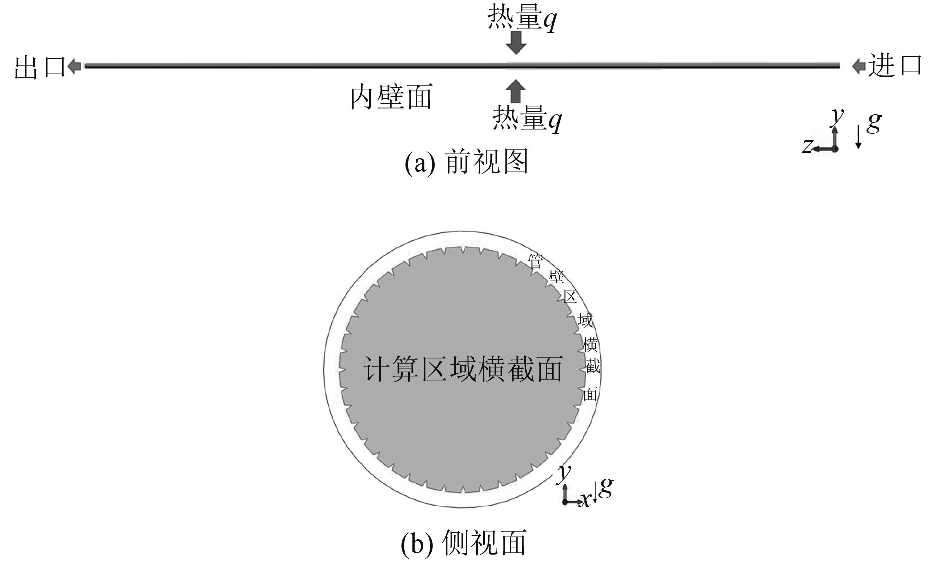
实际换热过程中,直肋管是有一定管壁厚度的强化管,在管壁中是一个金属材料稳态导热的过程,稳态换热过程中管壁温度不发生变化,只是将外加的热量传递给管内的沸腾过程,从数值计算角度是一个耦合问题,即管壁温度与流体温度需要同时计算;由于沸腾换热一般给定热流密度作为边界条件,为了计算过程的简化,将加热量直给定到管内壁面上。基准直肋管在管内沸腾过程中的计算区域的物理模型图如图2所示。

|
图 2 直肋管数值计算区域的物理模型图 Fig. 2 Diagram of micro-fin tube |
本节中直肋管管内的流动沸腾过程的数值模拟是采用Eulerian-Eulerian多相流数值模拟方法中的欧拉模型,在欧拉模型中制冷工质的液相被设置为连续相,气相当作分散相,连续相采用湍流模型,分散相采用零方程模型湍流模型,对流项采用二阶迎风格式处理、扩散项采用中心差分格式。轴方向为主流方向,入口设置为Inlet边界,入口流体是温度为5 ℃的饱和液相制冷工质R22及R410A,给定质量流量为100 kg·m–2·s–1;出口设置为Outlet边界;在周向按照外壁面热流密度为5 kW·m–2均匀折算到直肋管内壁面,内壁面为等热流WALL边界条件,计算采用Ansys CFX 14.0完成,分别计算了直肋管不同入口干度条件下沸腾换热特性。
下边分别介绍管内沸腾换热过程中的控制方程:
1)连续性方程
| $ \nabla \cdot \left( {{\gamma _\alpha }{\rho _\alpha }{U_\alpha }} \right) = \varGamma _{\alpha \beta }^ + - \varGamma _{\beta \alpha }^ + \text{。} $ | (1) |
式中:
2)动量守恒方程
| $ \begin{split} & \nabla \cdot \left( {{\gamma _\alpha }\left( {{\rho _\alpha }{U_\alpha } \otimes {U_\alpha }} \right)} \right) + {\gamma _\alpha }\nabla p= \\ & \nabla \cdot \left( {{\gamma _\alpha }{\eta _\alpha }} \right)\left( {\nabla {U_\alpha } + {{\left( {\nabla {U_\alpha }} \right)}^{\rm T}}} \right) + {\gamma _\alpha }{\rho _\alpha }g + {M_\alpha }\text{。} \end{split} $ | (2) |
式中:
| $ {\eta _{ld}} = {\eta _l} + {\eta _{lt}} + {\eta _{lv}}\text{,} $ | (3) |
| $ {\eta _{vd}} = {\eta _v} + {\eta _{vt}}\text{。} $ | (4) |
式中:液相当量动力粘度系数
3)能量守恒方程
| $ \begin{split} & \nabla \cdot \left( {{\gamma _\alpha }\left( {{\rho _\alpha }{U_\alpha }{h_\alpha }} \right)} \right) =\\ & \quad \nabla \cdot \left( {{\gamma _\alpha }{\lambda _\alpha }\left( {\nabla {T_\alpha }} \right)} \right) + \left( {\varGamma _{\alpha \beta }^ + {h_{\beta {\rm{s}}}} - \varGamma _{\beta \alpha }^ + {h_{\alpha {\rm{s}}}}} \right) + {q_\alpha }\text{。} \end{split} $ | (5) |
式中:
4)体积守恒方程
| $ {\gamma _\alpha } + {\gamma _\beta } = 1\text{。} $ | (6) |
在整个管内沸腾换热过程中,管内的任何区域内气液相制冷工质的体积分数为1,即充满整个空间。
2.2 沸腾换热模型本节微肋管管内沸腾过程中数值模拟研究中的沸腾换热模型采用商业软件自带的RPI沸腾模型(由Kural和Pidowski[12]在Rensselaer Polytechnic Institute首次提出)。RPI沸腾模型假设沸腾过程中壁面处的网格尺寸大于汽化核心区域的物理尺寸,它不分析沸腾机理中汽化核心区域产生气泡的过程,而是研究在已有气泡产生基础上的沸腾换热过程。RPI沸腾模型的核心思想是对沸腾过程中的外加热量进行分配,对于过冷沸腾过程,外加热流密度可通过下式分配:
| $ {q_w} = {q_c} + {q_q} + {q_e}\text{。} $ | (7) |
式中:

|
图 3 壁面热流密度分配示意图 Fig. 3 The distribution of heat flux on wall |
按照沸腾换热RPI模型中的假设,3种热流密度可分别通过式(8)~式(10)求解得出:
| $ {q_c} = {A_1}{h_c}\left( {{t_w} - {t_l}} \right)\text{,} $ | (8) |
| $ {q_q} = {A_2}{h_q}\left( {{t_w} - {t_l}} \right)\text{,} $ | (9) |
| $ {q_e} = \dot m\left( {{h_v} - {h_l}} \right)\text{。} $ | (10) |
式中:
从以上分析中可以看到,采用RPI沸腾换热模型计算的结果好坏与汽泡面积分数
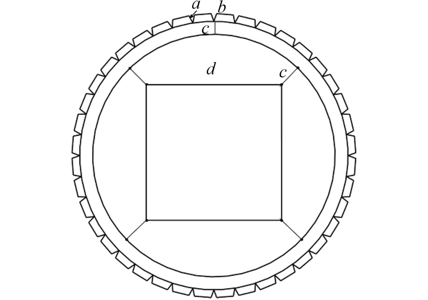
直肋管在数值模拟中的网格采用Gambit 2.3.16划分,六面体结构化网格。在进行正式分析前,首先对网格的独立性进行考核,验证过程中总共采用了8套网格,网格数最小为68.4万,最大为380万。直肋管横截面的网格划分示意图如图4所示,通过将横截面切割成46个不同的区域,将每个区域用结构化的四面体网格进行划分,图中的a,b,c,d分别为齿斜坡、齿间距、径向、中心区域边长方向上的网格数,通过a,b,c,d可以决定横截面上的网格数量。

|
图 4 直肋管横截面网格划分区域示意图 Fig. 4 Diagram of micro-fin tube cross-section grid |
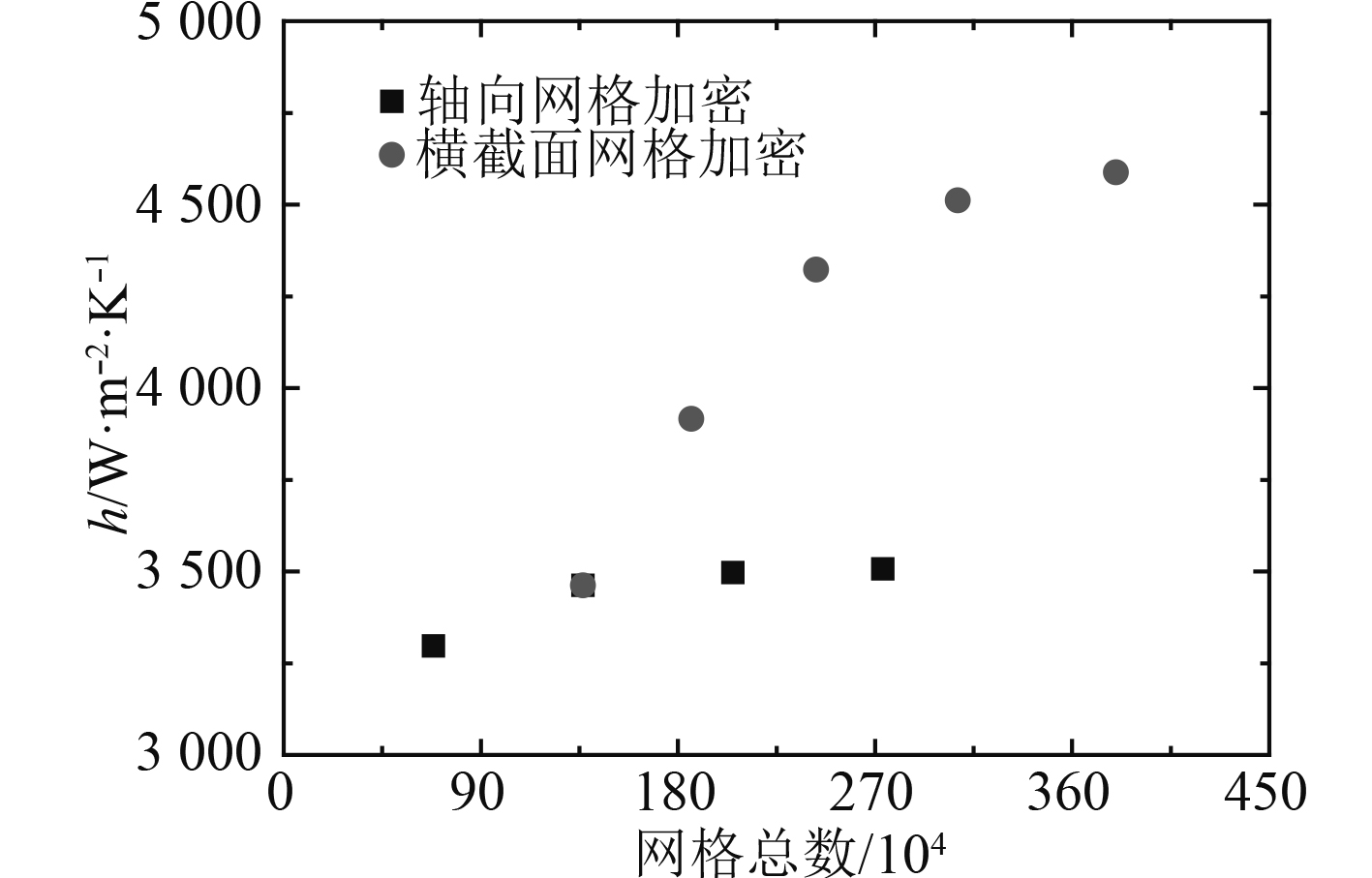
对于工质R410A,直肋管管内沸腾中的平均干度为0.5的整个管长的平均换热系数随网格数量的变化如图5所示,横截面网格数目的变化对换热系数影响要比轴向网格变化大。由于横截面上的网格变化引起网格数量急剧增大,因此首先固定横截面上的网格数目,根据轴向网格不同换热系数的变化规律,选定轴向网格数量为200,此时与轴向网格数量为300,400的换热系数计算结果误差在1.3%之内;固定轴向网格数为200,改变横截面的网格数目,选定齿上网格数目为9,此时换热系数计算结果误差为1.7%,最终选择307万的网格用于直肋管管内沸腾的计算。

|
图 5 直肋管管内沸腾换热系数随网格数量的变化 Fig. 5 The heat transfer coefficient of micro-fin tube with grid number variation |
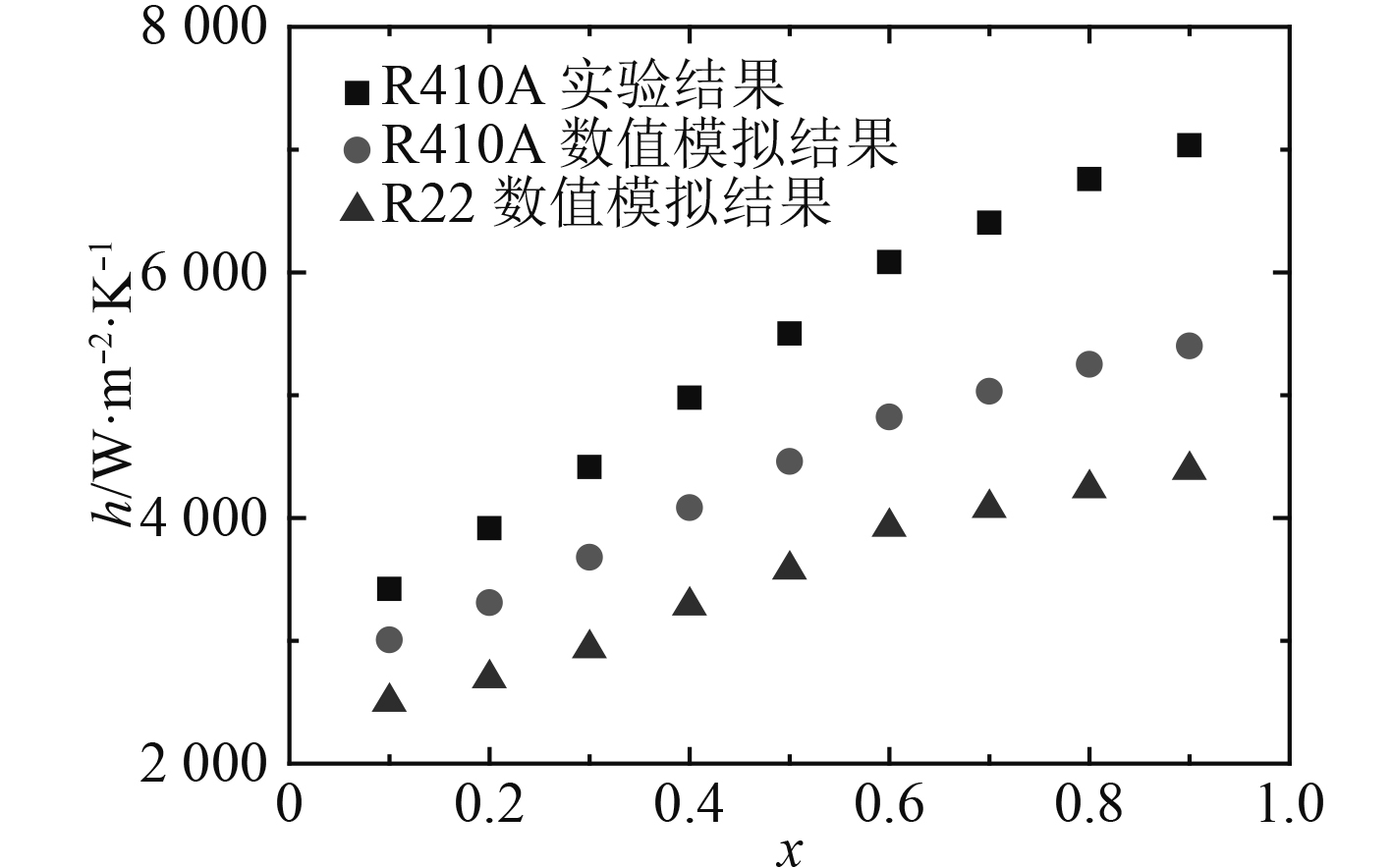
R410A在不同干度条件下的换热系数随干度变化的数值模拟结果与相同工况下实验结果[14]进行比较并列于图6中。从图中可以看出,换热系数数值模拟结果均要比实验结果小一些。负偏差产生的原因可能与模型本身有关,因为现有的RPI模型的参数主要是从平表面的实验结果中提取的,对于带微肋表面的微肋管由于汽化核心区域的增加,换热系数会得到一定程度的提高从而减少模型误差。实验过程中换热系数的数值模拟结果与实验结果的平均偏差为–18%而最大偏差为–26%。考虑到沸腾换热实验数据本身的不确定性,总体上采用Euler多相流模型和RPI沸腾模型的计算结果基本能够反映直肋管管内沸腾过程中的换热特性。从图中可以看出,不同干度条件下R410A的换热系数要比R22小,大约要高30%~40%,在进行制冷剂替换过程应考虑两种制冷工质的换热特性。

|
图 6 直肋管管内沸腾过程中换热系数与实验结果的比较 Fig. 6 Comparison between computational and experimental results |
本文应用Euler多相流模型及RPI沸腾换热模型计算了R22和R410A在外径为5 mm的直肋管管内沸腾过程中的换热特性,研究表明:数值计算结果基本能够反映直肋管管内沸腾过程中的换热特性,与文献中实验结果差距不大;相同条件下R410A的换热特性要比R22高,约是1.3~1.4倍,在舰船空调换热器进行制冷工质替换及设计优化过程要予以考虑。
| [1] |
FUJIE K, ITOH M, INNAMI T, et al. Heat transfer pipe. US patent 4, 044, 797, 1977[assigned to Hitachi, Ltd.]
|
| [2] |
AKIO M, YUSUKE O. Condensation heat transfer of herringbone micro fin tubes[J]. International Journal of Thermal Science, 2002, 41: 639-645. DOI:10.1016/S1290-0729(02)01358-3 |
| [3] |
DONGSOO J, HEUNGSEOK L, DONGSOO B, et al. Nucleate boiling heat transfer coefficients of flammable refrigerants on various enhanced tubes[J]. International Journal of Refrigeration, 2005, 28: 451-455. DOI:10.1016/j.ijrefrig.2004.07.024 |
| [4] |
ZHANG Zhengguo, LI Qianxia, XU Tao, et al. Condensation heat transfer characteristics of zeotropic refrigerant mixture R407C on single, three-row petal-shaped finned tubes and helically baffled condenser[J]. Applied Thermal Engineering, 2012, 39: 63-69. DOI:10.1016/j.applthermaleng.2012.01.021 |
| [5] |
LI Guan-qiu, WU Zan, LI Wei, et al. Experimental investigation of condensation in micro-fin tubes of different geometries[J]. Experimental Thermal and Fluid Science, 2012, 37: 19-28. DOI:10.1016/j.expthermflusci.2011.09.008 |
| [6] |
KUO C. S., WANG. C.C.. In-tube evaporation of HCFC-22 in a 9.52 mm micro-fin/smooth tube[J]. International Journal of Heat and Mass Transfer, 1996, 39: 2556-2569. |
| [7] |
KUOC. S., WANG. C.C.. Horizontal flow boiling of R22 and R407C in a 9.52 mm micro-fin/smooth tube[J]. Applied Thermal Engineering, 1996, 16: 713-731. |
| [8] |
LALLEMAND M., BRANESCU C., HABERSCHILL P.. Local heat transfer coefficients during boiling of R22 and R407C in horizontal smooth and micro-fin tubes[J]. International Journal of Refrigeration, 2001, 24: 57-72. DOI:10.1016/S0140-7007(00)00064-5 |
| [9] |
ADRIANA G, GIUSEPPE P V. Evaporation of refrigerants in a smooth horizontal tube: prediction of R22 and R507 heat transfer coefficients[J]. Applied Thermal Engineering, 2004, 24: 2189-2206. DOI:10.1016/j.applthermaleng.2004.02.006 |
| [10] |
KIM Man-hoe, SHIN Joeng-seob. Evaporating heat transfer of R22 and R410A in horizontal smooth and micro-fin tubes[J]. International Journal of Refrigeration, 2005, 28: 940-948. DOI:10.1016/j.ijrefrig.2005.01.016 |
| [11] |
SATO Y, SADATOMI M, SEKOGUCHI K. Momentum and heat transfer in two-phase bubble flow-theory[J]. International Journal of Multiphase Flow, 1981, 7(2): 167-177. DOI:10.1016/0301-9322(81)90003-3 |
| [12] |
KURUL N, PODOWSKI M. On the modeling of multi-dimensional effects in boiling channels[C]//Minneapolis. 1991.
|
| [13] |
袁培.板翅式换热器两相流分配器优化及锯齿型翅片传热特性的研究[D].西安:西安交通大学,2013. YUAN Pei. Research on the optimization for two-phase distributor of plate-fin heat exchanger and the heat transfer character of offset strip fin[D]. Xi'an, Xi'an Jiaotong University, 2013. |
| [14] |
姜国宝.微肋管管内流动相变换热及阻力特性实验研究和数值模拟[D].西安:西安交通大学,2016. JIANG Guobao. Experimental and numerical study on the convective phase change heat transfer and pressure drop characteristics in micro-fin tubes[D]. Xi'an, Xi'an Jiaotong University, 2016. |
| [15] |
State Bureau of Quality Technical Supervision, Ministry of Health, SEPA in PRC. GB/T 18883-2002, Indoor air quality standard[S] Beijing: China Standards Press, 2002.
|
| [16] |
China State Shipbuilding Industry Corporation. CB/T3774-996, Air conditioning, ventilation design conditions and calculation standard of Ship control[S].
|
| [17] |
State Bureau of Quality Technical Supervision, China national standardization administration commission. GB/T 1880-2015, Air cleaner[S], Beijing: China Standards Press, 2015.
|
| [18] |
ZHU Y X. Architectural Environment (4th edition)[M], Beijing: China Building Industry Press, 2016.
|
| [19] |
QI M W, LI X F, HUANG H. Tracer gas method of using the body as CO2 source measurement method to explore the air changes in the dormitory
[J]. building science, 2013, 29(6): 52-57, 58. |
| [20] |
HUANG S D, XIONG J Y, ZHANG YP. Comparative research between closed chamber C-history method and other methods for measuring characteristic parameters of building materials[J]. CIESC Journal, 2012, 63(S1): 194-198. |
 2019, Vol. 41
