The reduction of vibration and noise is full of attention and challenging. The research of transfer law and attenuation measures of structural noise in vessels is important[1]. For the ship, which assembled by steel plate and steel section, the damping coefficient of material is low. And the obstruction of structure itself is limited at structural break[2 – 5] (such as physical properties of material, thickness and structure). In order to get higher sound insulation, the measure must be effective and assemble technology reasonably. That’s to say, the rigid isolation combines with elastic laminated in the ship structure.
In this paper, the wave propagation in hull structure with viscoelastic interlayer is analyzed according to wave theory. The longitudinal wave sound insulation formula of viscoelastic interlayer is given. At the same time, the vibration isolation performance of L-typed hull structure with viscoelastic interlayer is researched. Furthermore, polyurethane interlayer is introduced into power cabin’s vibration isolation design. The characteristics of polyurethane interlayer impending structure-borne sound are analyzed through model test.
2 LONGITUDINAL WAVE PROPAGATION IN VISCOELASTIC INTERLAYERWith the presumption of inserting the finite length viscoelastic interlayer in the two semi-infinite plate of hull, the viscoelastic medium and semi-infinite plate are rigid connection along the width direction. The longitudinal wave incidents from

|
Fig. 1 Longitudinal wave attenuation for elastic interlayer |
The transmission velocity which passed an interface is:
| ${v_{x2\infty }} = {v_{x1}}\frac{{2{Z_1}}}{{{Z_1} + {Z_2}}}{\text{,}}$ | (1) |
Where:
The thickness of finite viscoelastic body is l, so the equation (1) is the first through case of wave only. The first transmitted wave will reflect at the second interface:
| $r = \frac{{{Z_2} - {Z_1}}}{{{Z_2} + {Z_1}}}.$ | (2) |
When the reflected wave getting the first interface, it will be reflected, and the wave will be reflected at the boundary of elastic interlayer like this, again and again, and the traveling wave along positive x-axis is superposition of an infinite number of waves:
| ${v_2} = {v_{2\infty }}(1 + {r^2}{e^{ - j2{k_2}l}} + {r^4}{e^{ - j4{k_2}l}} + \cdots ){\text{,}}$ | (3) |
Because of r2<1, so equation (3) is infinite decreasing geometric progression:
| ${v_2} = \frac{{{v_{2\infty }}}}{{1 - {r^2}{e^{ - j{k_2}l}}}}{\text{,}}$ | (4) |
The wave speed of longitudinal wave when it transmits to the second plate[6]:
| ${v_{x3}} = {v_{x2}}{e^{ - j{k_2}l}}\frac{{2{Z_2}}}{{{Z_1} + {Z_2}}}{\text{,}}$ | (5) |
The sound transmission coefficient of longitudinal passed the viscoelastic interlayer is:
| $\begin{split}& \tau = {\left| {\frac{{{v_{x3}}}}{{{v_{x1}}}}} \right|^2} = {\left| {\frac{{4{Z_1}{Z_2}{e^{ - j{k_2}l}}}}{{{{\left( {{Z_1} + {Z_2}} \right)}^2} - {{\left( {{Z_2} - {Z_1}} \right)}^2}{e^{ - j2{k_2}l}}}}} \right|^2} = \\ & \frac{1}{{{{\cos }^2}{k_2}l + \frac{1}{4}{{({Z_1}/{Z_2} + {Z_2}/{Z_1})}^2}{{\sin }^2}{k_2}l}}.\end{split}$ | (6) |
When the materials of interlayer and hull plate are the same, when Z2/Z1=1, τ=1. Even if Z2/Z1≠1, just the k2l=nπ, τ=1. When
| $\tau = \frac{{4{{({Z_1}{Z_2})}^2}}}{{{{({Z_1}^2 + {Z_2}^2)}^2}}}{\text{,}}$ | (7) |
In general, the elastic interlayer is thin. Expand the trigonometric functions, equation (6) can be written:
| $\tau = \frac{4}{{1 + 1/4{{\left[ {({Z_1}/{Z_2}) - ({Z_2}/{Z_1})} \right]}^2}{{({k_2}l)}^2}}}{\text{,}}$ | (8) |
For the elastic interlayer,
| $\tau = \frac{1}{{1 + {{(\displaystyle\frac{{{Z_1}{k_2}l}}{{2{Z_2}}})}^2}}} = \frac{1}{{1 + {{(\displaystyle\frac{{\omega {Z_1}}}{{2{E_2}{S_2}/l}})}^2}}} = \frac{1}{{1 + {{(\displaystyle\frac{{\omega {Z_1}}}{{2{S_T}}})}^2}}}.$ | (9) |
Where: ST is the rigid of elastic interlayer,
The sound insulation of longitudinal wave in the hull plate with elastic interlayer:
| $R = 10\lg \left[ {1 + {{(\omega {Z_1}/2{S_T})}^2}} \right]\;\;\;{\rm{dB}}.$ | (10) |
The Fig. 2 shows the inhibitory properties of longitudinal wave in hull plate assembly set.1 whose thickness is 10 mm with different viscoelastic material. The variation of p-wave transmission loss with different material of viscoelastic interlayer is similar, in other words, the sound insulation increases with the frequency. With the reduction of Young’s modulus of interlayer, the degree of impedance mismatch is increased, so the sound isolation of longitudinal wave is increased.

|
Fig. 2 Longitudinal wave transmission loss with different modulus interlayer |

|
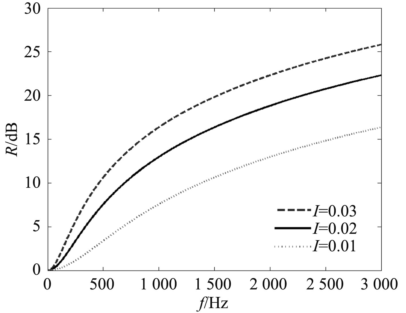
Fig. 3 Longitudinal wave transmission loss with different size of interlayer |
The Fig. 3 shows influence law of longitudinal wave in the hull plate about length of elastic material. For the higher sound isolation, the ST is as low as possible, that’s to say, the interlayer is as long as possible. But because of the phenomenon of total transmission when k2l=nπ, the greater of the l and the more situation of the total transmission, so they are contradictory. In fact, because of the elastic material(such as polyurethane, cork and rubber) has inner-damping, so when it is resonance, in other words, k2l=nπ, the total transmission won’t appear. Taking the loss factor η into consideration, the phenomenon is presented with complex wave number[7]:
| ${k_2}^ * \approx {k_2}(1 - 1/2j\eta ).$ | (11) |
Now the sound isolation is:
| ${R_{\min }} \approx 20\lg (\frac{{\pi \eta {Z_1}}}{{4{Z_2}}})\;\;\;{\rm{dB}}.$ | (12) |
The hull is made up by the plate racks and bulkheads, so it is significant to research the incident bending wave get into a L structure (such as the junction of planking and transverse bulkheads, and the junction of transverse bulkheads and inner bottom).The impedance mismatch can be increased in effect by laying the rigid vibration isolation mass at the corner of structure, it can refuse the transfer of vibration wave. But the rigid vibration isolation mass just reflects the energy of incident wave, and the energy of sound is not reduction in effect. If the viscoelastic interlayer is used to coordinate the rigid vibration isolation mass, it can reduction the transfer of vibration wave on its best with impedance mismatch some times, and the energy reflected at the corner of structure is absorbed and consumed in effect at the same time. It is significant to the application of vibration and noise reduction for vessel.

|
Fig. 4 Sketch of typical L-typed hull structure |

|
Fig. 5 Sketch of L-typed structure with blocking mass layout elastic interlayer |
The plate bending wave incident into the viscoelastic material in the plate 1, it will produce the near-field wave and transmission wave. When the vibration wave transferring to the L structure connection with vibration isolation mass, the energy of bending wave will be transmitted and reflected again, and the wave transformation will occur in the two plates, and it will produce the longitudinal wave transmitted and reflected:
| $\begin{aligned}& {v_{y2}}({x_1}) = {v_{y1}}({t_1}{e^{ - i{k_{B1}}{x_2}}} + {t_{j1}}{e^{ - {k_{B1}}{x_2}}}) \\ & ({e^{ - i{k_{B1}}{x_1}}} + {r_2}{e^{i{k_{B1}}{x_1}}} + {r_j}_2{e^{{k_{B1}}{x_1}}}),\end{aligned}$ | (13) |
| ${v_{y3}}({x_2}) = {v_{y1}}({t_1}{e^{ - i{k_{B1}}{x_2}}} + {t_{j1}}{e^{ - {k_{B1}}{x_2}}})({t_2}{e^{ - i{k_{B2}}{x_2}}} + {t_{j2}}{e^{ - {k_{B2}}{x_2}}}).$ | (14) |
| ${v_{x2}}({x_1}) = {v_{x2}}{e^{i{k_{L1}}{x_1}}},$ | (15) |
| ${v_{x3}}({x_2}) = {v_{x3}}{e^{ - i{k_{L2}}{x_2}}}.$ | (16) |
Where: t1 and tj1 are transmission coefficient and near-field wave transmission coefficient of bending wave transferring into the viscoelastic interlayer. r2 and rj2 are reflect coefficient and near-field wave reflect coefficient of bending wave at corner of L structure respectively. t2 and tj2 are transmission coefficient and near-field wave transmission coefficient at corner, respectively. kB1、kB2、kL1、kL2 are wave number of bending wave and longitudinal wave in plate 1 and 2, respectively.
According to the boundary conditions at corner of L structure with vibration isolation mass, the linear equations about r2, rj2, t2, tj2 can be achieved:
| $At = b,$ | (17) |
Where: t is a column vector
Solving the linear equations, the transmission coefficient of bending wave in L structure with viscoelastic interlayer combined with vibration isolation mass is obtained:
| ${\tau _{BB}} = \frac{{{k_{B2}}^3{B_2}}}{{{k_{B1}}^3{B_1}}}|{t_2}{|^2}.$ | (18) |
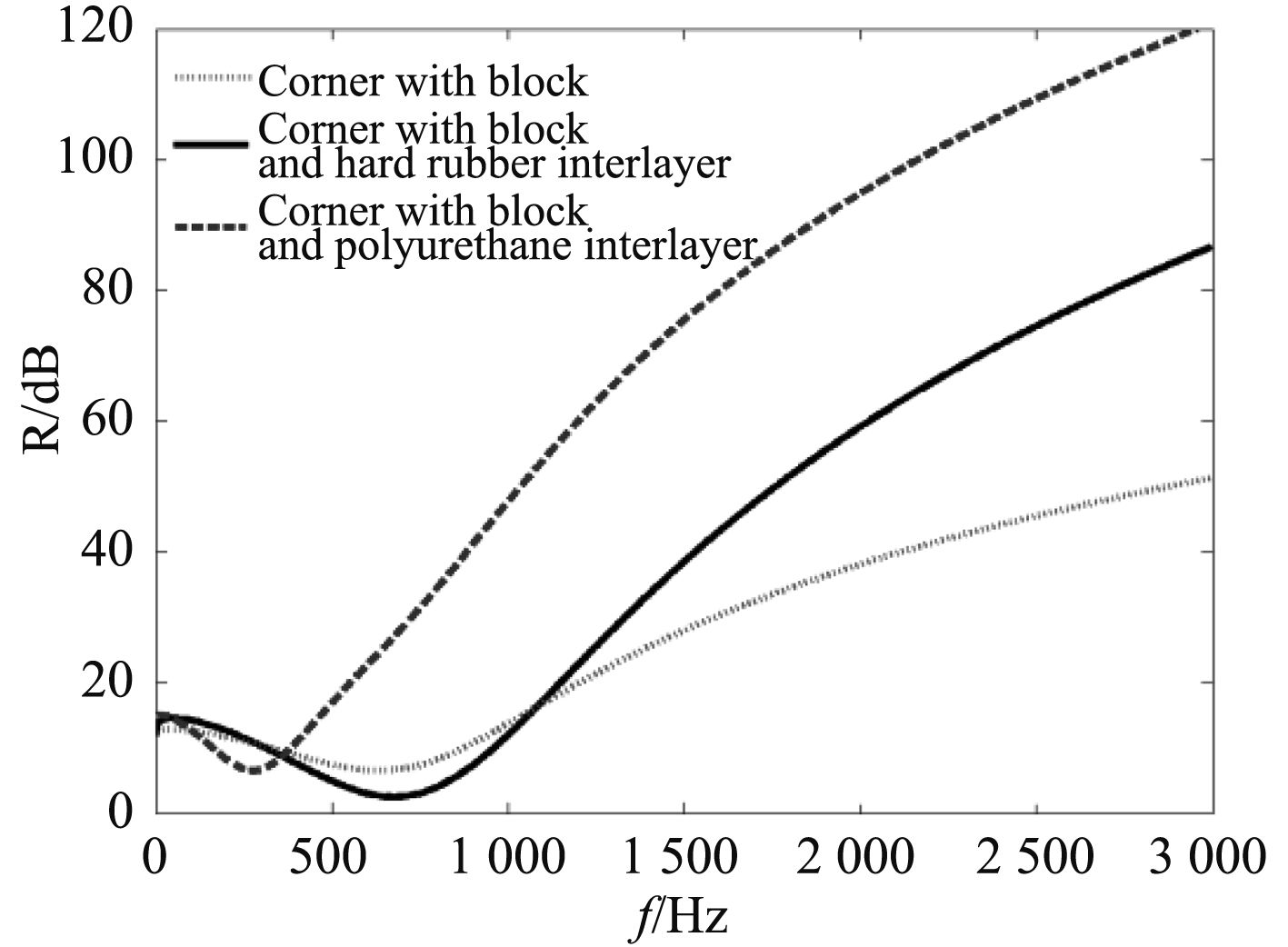
The Fig. 6 shows the comparative flexural wave transmission loss curves of L structure with vibration isolation mass combined with viscoelastic interlayer which is made up by ceilings and bulkheads. The thickness of ceiling is 12 mm, the thickness of bulkhead is 16 mm, the section size of vibration isolation mass at corner is 72×72 mm, the length of viscoelastic interlayer is 10 mm, the Young’s modulus of hard rubber interlayer is 5e8, and the Young’s modulus of polyurethane is 8e6.

|
Fig. 6 Isolation performance curves of L-typed structure with blocking mass layout elastic interlayer |
As the figure above shown, the rigid vibration isolation mass at bulkhead and ceiling make the impedance mismatches degree of structure increased, and the transmission of vibration wave is Inhibited. Based on that, the viscoelastic interlayer is combined to construct the impedance mismatch many times. The energy of vibration is blocked or limited in a certain region by the vibration isolation mass, and it is absorbed by the viscoelastic interlayer. The performance of vibration isolation is increased by the new resistance wave technology, and the cutoff frequency of vibration isolation is reduced at the same time. The mechanical excitation result from the variety of ship equipment can be isolated in effect.
4 EXPERIMENTAL RESULTSBased on the theoretical analysis above, the model test of polyurethane interlayer impending hull structure-borne sound is carried out.

|
Fig. 7 Sketch of hull cabin with polyurethane interlayer |
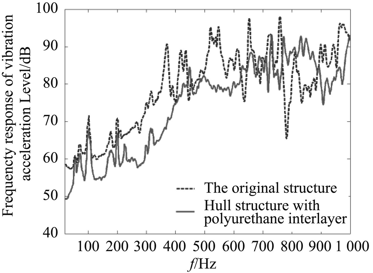
The model test is about the vibration excitation in 20~1 000 Hz. The frequency response curves of power cabin’s variation acceleration level with and without polyurethane interlayer are shown in Fig. 8.

|
Fig. 8 Comparison curves of power cabin’s variation acceleration level |
As the figure shown, the hull structure-borne sound is obviously reduced above 125 Hz. The test data shows that the hull shell’s 20 ~ 1 000 Hz variation acoustic level is reduced more than 5 dB with polyurethane interlayer. With the combination of polyurethane interlayer with blocking mass, the vibration energy is blocked and limited in a certain field, and it is absorbed by the polyurethane interlayer. The vibration energy in slot frequency of propulsion motor is reduced and absorbed by structuring multi impedance mismatch.
Compared to damping materials or blocking mass separate application, it has higher cost-efficient. It is valued for engineering application of structure-borne sound control.
5 CONCLUSIONSThe main conclusions are as following:
1) The vibration isolation performance of interlayer is increased with Young’s modulus reduction and its length addition, and the Young’s modulus is the main factor.
2) Combination of finite-length polyurethane interlayer with blocking mass can enhance the vibration isolation performance and expand isolation frequency band, which has a high cost-effective ratio.
3) The test data shows that the hull shell’s 20 ~ 1 000 Hz variation acoustic level is reduced more than 5 dB with polyurethane interlayer.
| [1] | L CEMER, M HECKL, E E UNGAR. Structure-borne sound. Berlin: Springer-Verlag. 1988:316–334. |
| [2] | ZHI Zhong-yan, CHUAN Zeng-zhang. Attenuation and localization of bending waves in a periodic/disordered fourfold composite beam[J]. Journal of Sound and Vibration, 2009, 327: 109–120. |
| [3] | JI Fang, YAO Xiong-liang. Structure-borne sound design of typical hull base[J]. Journal of Engineering Computation. 2012, 9(4). |
| [4] | B M EFIMTSOV, L A LAZAREV. Forced vibrations of plates and cylindrical shells with regular orthogonal system of stiffeners[J]. Journal of Sound and Vibration, 319(2007)41–54. |
| [5] | F G MITRI, Z E A FELLAH. Acoustic radiation force on coated cylinders in plane progressive waves[J]. Journal of Sound and Vibration, 308 2007, 308: 190-200. |
| [6] | S M HASHEMINEJAD, Y MIRZAEI. Free vibration analysis of an eccentric hollow cylinder using exact 3D elasticity theory[J]. Journal of Sound and Vibration , 2009, 326: 687–702. |
| [7] | JI Fang, YAO Xiong-liang. Experimental study on time-frequency of stiffened double hull sound radiation based on EMD[J]. Journal of Engineering Computation, 2012, 29(3). |
 2017, Vol. 39
