近年来,感应电机无速度传感器矢量控制算法取得了快速发展。许多学者进行了深入的研究,并提供了很多实用的方法,特别是模型参考自适应全阶观测方法已经引起了广泛关注,其中包括异步电机模型,观测器反馈增益和转子速度自适应律[1–4]。传统速度自适应法是基于李雅普诺夫稳定性理论和波波夫超稳定性理论[5–7]。为了加快收敛速度估计误差,极点配置是为了观察反馈增益矩阵设计的通常使用方法。然而,许多研究和实际工作都表明,即使在参数误差和测量噪声很小的情况下,基于全阶自适应观测器的感应电机无速度控制系统会产生不稳定现象。
本文讨论基于改进电压模型磁通估算方法,从而实现异步电机无速度传感器控制系统的稳定运行。通过理论分析及仿真,验证了本文提出新方法的正确性。
1 感应电机速度观测模型高精度、高分辨率的速度和位置传感器(如光电编码器等)价格昂贵,不仅提高了控制系统的成本,还限制了装置在恶劣环境下的应用。运用无速度传感器控制技术,可以在线估计感应电机的速度和位置,从而省去了传感器。
1.1 静止ABC轴系速度观测模型在静止ABC轴系中,定、转子磁链和电压矢量方程为:
| ${\psi _s} = {L_s}{i_s} + {L_m}{i_r}\text{,}$ | (1) |
| ${\psi _r} = {L_m}{i_s} + {L_r}{i_r}\text{,}$ | (2) |
| ${u_s} = {R_s}{i_s} + d{\psi _s}/dt\text{,}$ | (3) |
| $0 = {R_r}{i_r} + d{\psi _r}/dt - j{\omega _r}{\psi _r}\text{。}$ | (4) |
转子电压矢量方程中含有转子速度ωr,因此可用来获取转子速度信息,但是方程中有转子电流矢量ir,它是不可测量的,为此要将ir从方程中消去。
由式(2)可得:
| ${i_r} = \frac{1}{{{L_r}}}({\psi _r} - {L_m}{i_s})\text{,}$ | (5) |
将式(5)代入式(4),则有:
| ${\omega _r} = \frac{{\frac{{d{\psi _r}}}{{dt}} + \frac{1}{{{T_r}}}{\psi _r} - \frac{{{L_m}}}{{{T_r}}}{i_s}}}{{j{\psi _r}}}\text{,}$ | (6) |
式中定子电流is可取实测值,除此之外,还需要知道转子磁链矢量ψr及其微分dψr/dt。
由式(1)和式(2),可求得:
| ${\psi _r} = \frac{{{L_r}}}{{{L_m}}}({\psi _s} - L_s'{i_s})\text{,}$ | (7) |
式中
由式(3)可得:
| ${\psi _s} = \int {({u_s} - {R_s}{i_s}){\rm d}t} \text{,}$ | (8) |
由式(7)和式(8)可得:
| $\begin{array}{l}\displaystyle\frac{{{\rm d}{\psi _r}}}{{{\rm{d}}t}} \!=\! \displaystyle\frac{{{L_r}}}{{{L_m}}}(\frac{{{\rm d}{\psi _s}}}{{{\rm{d}}t}} - L_s'\frac{{{\rm d}{i_s}}}{{{\rm{d}}t}}) \!=\! \displaystyle\frac{{{L_r}}}{{{L_m}}}({u_s} - {R_s}{i_s} - L_s'\frac{{{\rm d}{i_s}}}{{{\rm{d}}t}})\text{,}\end{array}$ | (9) |
将
| ${\omega _r} = \displaystyle\frac{{ - \displaystyle\frac{{{\rm d}{\psi _{r\alpha }}}}{{{\rm d}t}} - \displaystyle\frac{1}{{{T_r}}}{\psi _{r\alpha }} + \displaystyle\frac{{{L_m}}}{{{T_r}}}{i_{s\alpha }}}}{{{\psi _{r\beta }}}}\text{。}$ | (10) |
定子磁链旋转坐标系速度观测模型方程表达为:
| ${u_s} - {R_s}{i_s} - L_s'\frac{{{\rm d}{i_s}}}{{{\rm{d}}t}} - \frac{{L_m^2{R_r}}}{{L_r^2}}{i_s} = - \frac{{{R_r}}}{{{L_r}}}({\psi _s} - L_s'{i_s}) + j{\omega _r}({\psi _s} - L_s'{i_s})\text{,}$ | (11) |
对上式进行化简得:
| ${u_s} \!-\! ({R_s} + \frac{{{L_s}{R_r}}}{{{L_r}}}){i_s} \!-\! L_s'\frac{{{\rm d}{i_s}}}{{{\rm{d}}t}} \!=\! - \frac{{{R_r}}}{{{L_r}}}{\psi _s} + j{\omega _r}({\psi _s} - L_s'{i_s})\text{。}$ | (12) |
方程是以静止αβ轴系表示的,现将其变换到沿定子磁场定向的同步旋转MT轴系中,则
| $\begin{aligned}[{u_s} - ({R_s} + \frac{{{L_s}{R_r}}}{{{L_r}}}){i_s} - L_s'\frac{{d{i_s}}}{{dt}}]{e^{ - j{\rho _s}}}\ = \\- \frac{{{R_r}}}{{{L_r}}}\left| {{\psi _s}} \right| + j{\omega _r}(\left| {{\psi _s}} \right| - L_s'i_s^M)\text{,}\end{aligned}$ | (13) |
因此可得出:
| $\left\{ \begin{array}{l}{u_M} = - \displaystyle\frac{{{R_r}}}{{{L_r}}}\left| {{\psi _s}} \right| + {\omega _r}L_s'{i_{sT}}\text{,}\\[8pt]{u_T} = {\omega _r}(\left| {{\psi _s}} \right| - L_s'{i_{sM}})\text{。}\end{array} \right.$ | (14) |
下面给出转子磁链观测电流模型方程式:
| $\left\{ \begin{array}{l} - {\omega _r}{\psi _{r\beta }} = \displaystyle\frac{{d{\psi _{r\alpha }}}}{{{\rm{d}}t}} + \displaystyle\frac{1}{{{T_r}}}{\psi _{r\alpha }} - \displaystyle\frac{{{L_m}}}{{{T_r}}}{i_{s\alpha }}\text{,}\\[8pt]{\omega _r}{\psi _{r\alpha }} = \displaystyle\frac{{d{\psi _{r\beta }}}}{{{\rm{d}}t}} + \displaystyle\frac{1}{{{T_r}}}{\psi _{r\beta }} - \displaystyle\frac{{{L_m}}}{{{T_r}}}{i_{s\beta }}\text{;}\end{array} \right.$ | (15) |
| $\left\{ \begin{array}{l}\displaystyle\frac{{d{\psi _{r\alpha }}}}{{{\rm{d}}t}} = \displaystyle\frac{{{L_m}}}{{{T_r}}}{i_{s\alpha }} - \displaystyle\frac{1}{{{T_r}}}{\psi _{r\alpha }} - {\omega _r}{\psi _{r\beta }}\text{,}\\[8pt]\displaystyle\frac{{d{\psi _{r\beta }}}}{{{\rm{d}}t}} = \displaystyle\frac{{{L_m}}}{{{T_r}}}{i_{s\beta }} - \displaystyle\frac{1}{{{T_r}}}{\psi _{r\beta }} + {\omega _r}{\psi _{r\alpha }}\text{;}\end{array} \right.$ | (16) |
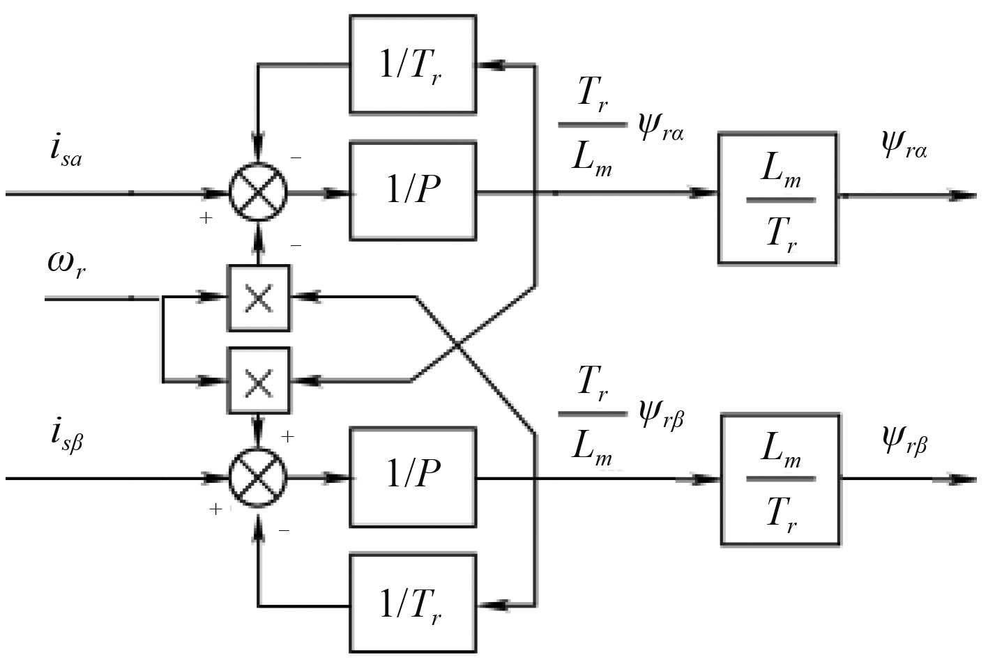
| $\left\{ \begin{array}{l}\displaystyle\frac{{{T_r}}}{{{L_m}}}\frac{{d{\psi _{r\alpha }}}}{{{\rm{d}}t}} = {i_{s\alpha }} - \displaystyle\frac{1}{{{L_m}}}{\psi _{r\alpha }} - {\omega _r}\displaystyle\frac{{{T_r}}}{{{L_m}}}{\psi _{r\beta }}\text{,}\\[8pt]\displaystyle\frac{{{T_r}}}{{{L_m}}}\displaystyle\frac{{d{\psi _{r\beta }}}}{{{\rm{d}}t}} = {i_{s\beta }} - \displaystyle\frac{1}{{{L_m}}}{\psi _{r\beta }} + {\omega _r}\displaystyle\frac{{{T_r}}}{{{L_m}}}{\psi _{r\alpha }}\text{。}\end{array} \right.$ | (17) |
将式(17)转换成原理框图,如图1所示。
|
图 1 转子磁链观测器电流模型原理框图 Fig. 1 Current model principle block diagram of rotor flux estimator |
电压模型表达式如下:
| ${u_s} = {R_s}{i_s} + {\rm d}{\psi _s}/{\rm{d}}t\text{,}$ | (18) |
当已知电压、电流、定子电阻可以求取电机定子磁链:
| ${\psi _s} = \int {({u_s} - {R_s}{i_s}} ){\rm{d}}t\text{。}$ | (19) |
因纯积分存在零漂,可采用一阶低通滤波器代替纯积分环节,从而清除零漂现象。
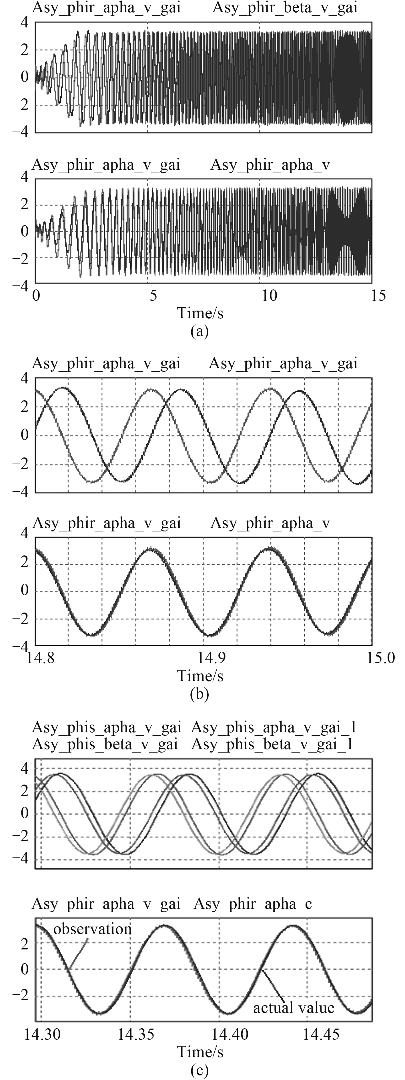
2.3 转子磁链观测器改进电压模型改进型电压模型先通过S/(S+λHωsTs)滤波器、再通过1/(S+λLωsTs)滤波器,最后对幅值及相位进行补偿,原理框图如图 2 所示,系数λH=0.1、λL=0.2。仿真波形如图3(a)、图3(b)所示,图3(c)是幅值及相位补偿前后定子磁链仿真对比波形、电压模型与电流模型转子磁链仿真对比波形。基于这种改进型方法需要对幅值及相位进行补偿,观测的磁链波形比较准确。

|
图 2 转子磁链观测器改进电压模型 Fig. 2 The improved voltage model of rotor flux estimator |
|
图 3 转子磁链观测器改进电压模型仿真波形 Fig. 3 The improved voltage model simulation waveform of rotor flux estimator |
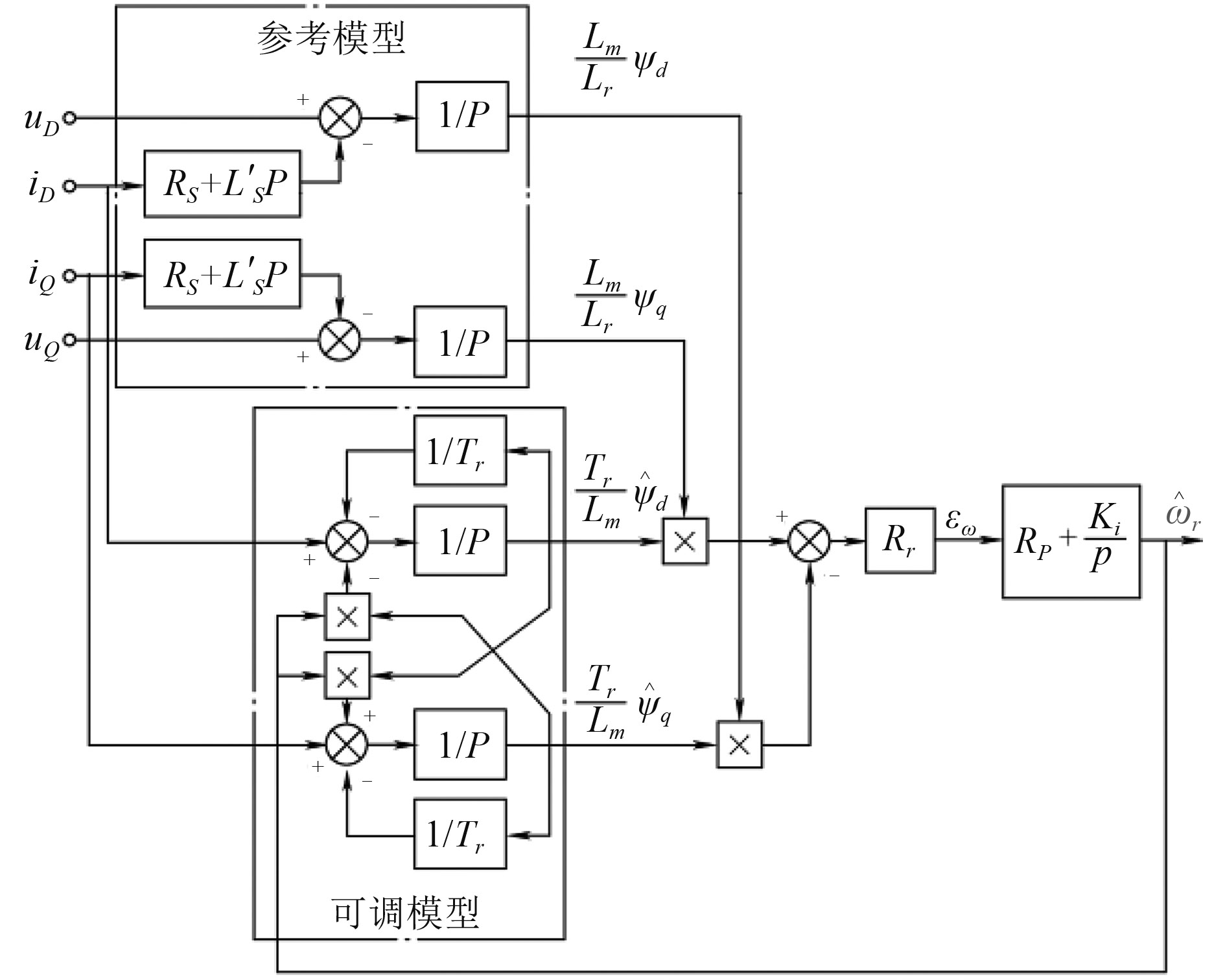
上面2种对速度观测是采用公式推导,即开环方式,且电角频率表达式中存在微分项,在离散化求解过程中会产生较大毛刺,计算结果会不太准确。下面采用模型参考自适应系统(Model Reference Adaptive System,MRAS),即一种闭环方式,这种模型主要包含参考模型、可调模型及自适应机构3部分。参考模型通常采用电压模型观测出电机转子磁链,可调模型通常采用电流模型观测出电机转子磁链,自适应机构采用电压、电流模型计算的磁链值交叉相乘,将这个交叉相乘的结果经过PI控制器,PI控制器的输出作为电角频率值,并将这个计算的电角频率值送入电流模型进行实时修正,使电压模型与电流模型观测的转子磁链完全吻合,这样实现了电角频率的实时观测。图4为模型参考自适应系统原理框图。
|
图 4 模型参考自适应系统原理框图 Fig. 4 The principle diagram of model reference adaptive system |
当电机参数比较准确时,估计出的ψr和ωr能始终映射出电动机的真实状态。但当电阻Rs不准确,在低速时对观测的结果产生影响;纯积分器引起的误差积累或直流温漂等问题也会对观测的结果产生影响。除定子电阻Rs外,转子电阻Rr以及电感Lm和Lr同样存在不准确性,在运行中也会发生变化,这些都会影响MRAS在低速时的应用和估计结果的准确性。
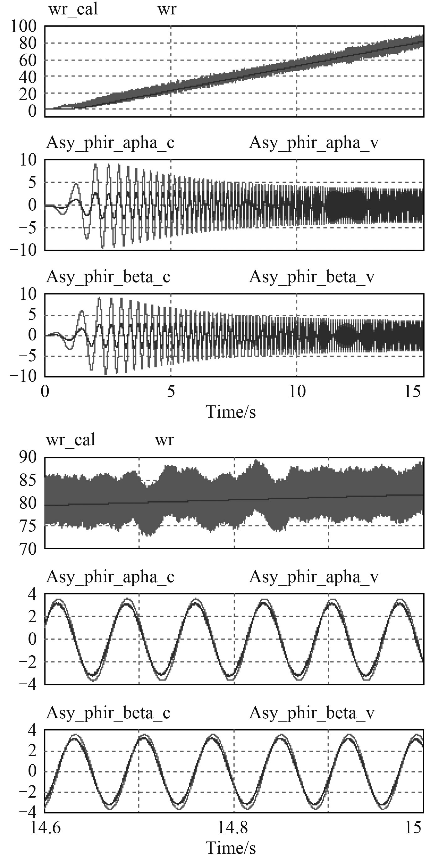
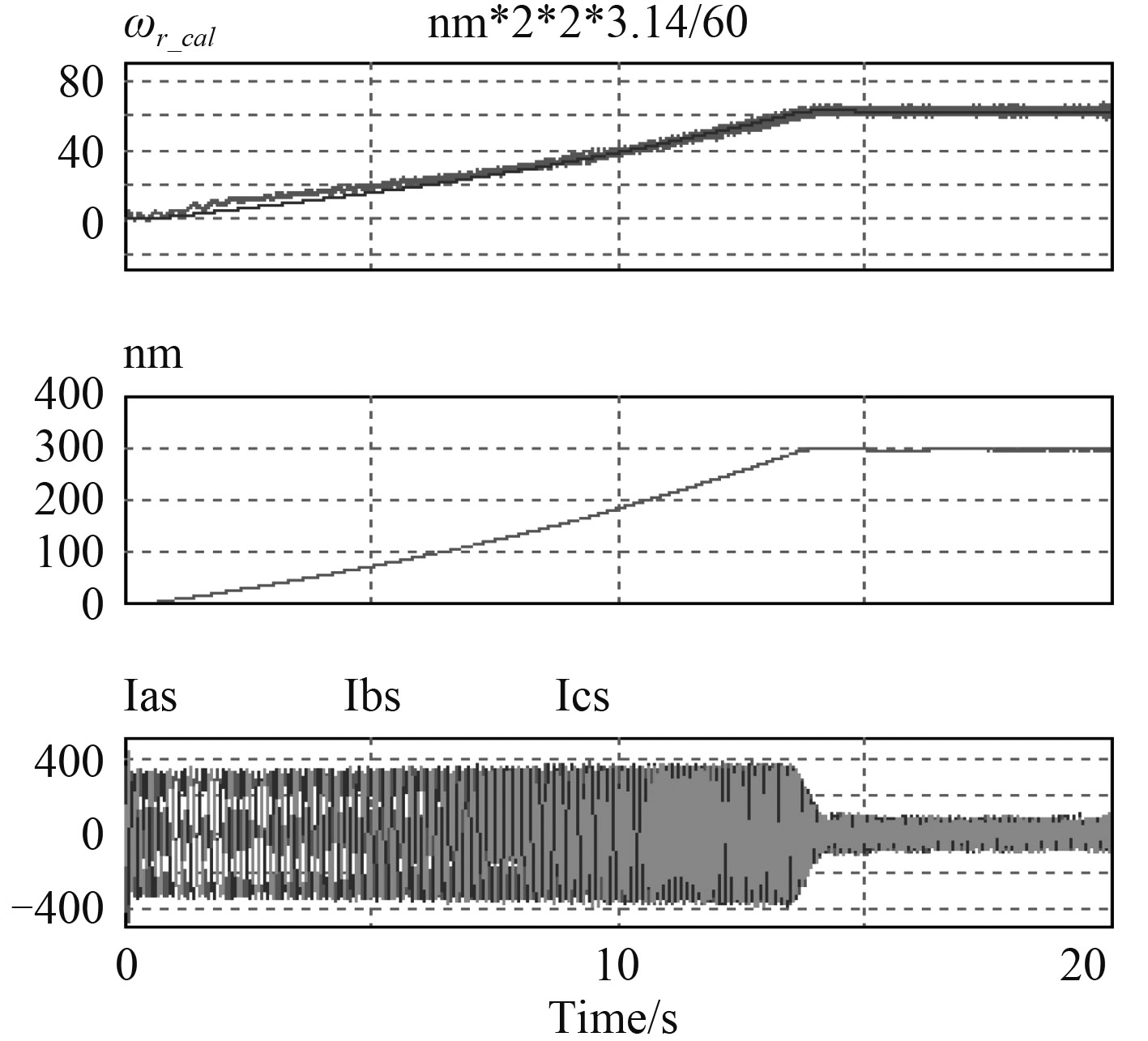
图5为采用间接磁场定向闭环控制,角速度ωr还是根据速度编码器检测的值代入计算,基于参考自适应模型进行角速度ωr_cal观测,但不参于闭环控制。图6为采用间接磁场定向闭环控制,基于参考自适应模型进行角频率ωr_cal观测并参于闭环控制。采用速度PI外环,电流内环控制,速度参考值为300 r/min,从仿真波形可以看出,观测的电角频率值与实际值接近。
|
图 5 参考自适应模型磁链及转速观测仿真波形 Fig. 5 Model reference adaptive flux observer and speed observation simulation waveform |
|
图 6 间接磁场定向闭环控制——参考自适应模型闭环控制仿真波形 Fig. 6 The indirect field-oriented control - model reference adaptive closed-loop control simulation waveform |
与原有带速度传感器交流传动控制系统相比,无速度传感器控制系统具有更高的可靠性和更低的成本,明显减小电机的安装体积,并可以工作在更恶劣的环境下。本文采用新型磁链观测模型进行感应电机闭环控制,速度观测及闭环控制效果良好。
| [1] | KUBOTA H, MATSUSE K, NAKANO T. DSP-based speed adaptive flux observer of induction motor[J].IEEE Trans. on Industry Applications, 1993, 29(2): 344–348. DOI: 10.1109/28.216542 |
| [2] | YANG G, CHIN T H. Adaptive speed identification scheme for a vector controlled speed sensorless inverter induction motor drive[J].IEEE Trans. on Industry Applications, 1993, 29(4): 820–825. DOI: 10.1109/28.232001 |
| [3] | TAJIMA H, GUIDI G, UMIDA H. Consideration about problems and solutions of speed estimation method and parameter tuning for speed sensorless vector control of induction motor drives[J].IEEE Trans. on Industry Applications, 2002, 38(2): 1282–1289. |
| [4] | 王坚, 年晓红, 桂卫华, 等. 新型异步电机无速度传感器控制方法[J].中国电机工程学报, 2008, 28(3): 96–101. |
| [5] | 张永昌, 赵争鸣, 张颖超. 基于全阶观测器的三电平逆变器感应电机无速度传感器矢量控制系统[J].电工技术学报, 2008, 23(11): 34–40. DOI: 10.3321/j.issn:1000-6753.2008.11.006 |
| [6] | 范蟠果, 杨耕. 感应电机无速度传感器控制自适应速度观测器[J].电机与控制学报, 2008, 12(6): 621–628. |
| [7] | 张永昌, 赵争鸣. 基于自适应观测器的感应电机无速度传感器模糊矢量控制[J].电工技术学报, 2010, 25(3): 40–47. |
| [8] |
杨光明, 王志飞. 异步电动机矢量控制系统的仿真研究[J].船电技术, 2009, 29(8): 27–31.
YANG Guang-ming, WANG Zhi-fei. Simulation of vector control system for asynchronous motor[J].Marine Electric Electronic Enginerring, 2009, 29(8): 27–31. |
 2017, Vol. 39
